US7806480B2 - Latch rear seat back operation - Google Patents
Latch rear seat back operation Download PDFInfo
- Publication number
- US7806480B2 US7806480B2 US12/180,719 US18071908A US7806480B2 US 7806480 B2 US7806480 B2 US 7806480B2 US 18071908 A US18071908 A US 18071908A US 7806480 B2 US7806480 B2 US 7806480B2
- Authority
- US
- United States
- Prior art keywords
- cable
- seat back
- seat
- lock actuator
- handle
- Prior art date
- Legal status (The legal status is an assumption and is not a legal conclusion. Google has not performed a legal analysis and makes no representation as to the accuracy of the status listed.)
- Expired - Fee Related
Links
Images


Classifications
-
- B—PERFORMING OPERATIONS; TRANSPORTING
- B60—VEHICLES IN GENERAL
- B60N—SEATS SPECIALLY ADAPTED FOR VEHICLES; VEHICLE PASSENGER ACCOMMODATION NOT OTHERWISE PROVIDED FOR
- B60N2/00—Seats specially adapted for vehicles; Arrangement or mounting of seats in vehicles
- B60N2/24—Seats specially adapted for vehicles; Arrangement or mounting of seats in vehicles for particular purposes or particular vehicles
- B60N2/32—Seats specially adapted for vehicles; Arrangement or mounting of seats in vehicles for particular purposes or particular vehicles convertible for other use
- B60N2/36—Seats specially adapted for vehicles; Arrangement or mounting of seats in vehicles for particular purposes or particular vehicles convertible for other use into a loading platform
- B60N2/366—Seats specially adapted for vehicles; Arrangement or mounting of seats in vehicles for particular purposes or particular vehicles convertible for other use into a loading platform characterised by the locking device
Definitions
- the present invention relates to foldable seat backs that are operable by a user with a single hand.
- the optimal seat back design also resists the forces of cargo within the trunk space pushing against the seat backs. In such designs, it is typically necessary for a vehicle user to use both hands in folding the rear seats in order to increase storage space. Although such designs work reasonably well, the ever increasing competitive nature of the automotive industry requires designs with improved functionality.
- the present invention solves one or more problems of the prior art by providing in at least one embodiment a vehicle seat that is foldable by a single hand.
- the vehicle seat of this embodiment includes a seat back and a seat bottom.
- the seat back is positionable in a design (upright) position and a folded position.
- the seat back at least partially defines a portion of a vehicle storage compartment. In the folded position, the storage compartment is larger and able to hold more items than when the seat back is in the upright position.
- the present embodiment is operable by a user with a single hand.
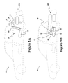
- FIG. 1A is a schematic illustration of a foldable vehicle seat in an upright position
- FIG. 1B is a schematic illustration of a foldable vehicle seat in a folded position
- FIG. 2 is a schematic illustration of the seat back frame allowing single handed operation
- FIG. 3A is a schematic illustration of a first lock actuator which is positionable in a locked and release position
- FIG. 3B is a schematic illustration of a second lock actuator which is positionable in a locked and release position
- FIG. 4 is a schematic illustration of the operation of the cable actuation system.
- FIG. 1A provides a schematic illustration of a vehicle seat in an upright position.
- FIG. 1B provides a schematic illustration of a vehicle seat in a folded position.
- Vehicle 10 includes vehicle seat 12 .
- Vehicle seat 12 includes seat back 14 and seat bottom 16 .
- Seat back 14 is positionable in design (upright) position 20 and folded position 22 .
- Seat back 14 at least partially defines a portion of vehicle storage compartment 26 .
- storage compartment 26 is larger and able to hold more items than when seat back 14 is in upright position 20 .
- the present embodiment is operable by a user with a single hand.
- FIG. 2 is a schematic illustration of the seat back frame allowing single handed operation.
- Seat back 14 includes seat back frame 30 .
- Seat back frame 30 includes latching system 32 which includes first handle 34 and second handle 36 which are in communication with cable actuation system 40 . Operation of either first handle 34 or second handle 36 causes cable actuation system 40 to release seat back 14 so that seat back 14 may be moved to the folded position 22 .
- FIG. 3A provides a schematic illustration of a first lock actuator which is positionable in a locked and release position.
- FIG. 3B provides a schematic illustration of a second lock actuator which is positionable in a locked and release position.
- Cable actuation system 40 includes first lock actuator 42 that is positionable in first locked setting 44 and first release setting 46 .
- first lock actuator 42 includes lever 50 which is pivotable about pivot point 52 along direction d 2 when first lock actuator 42 moves between first locked setting 44 and first release setting 46 .
- First lock setting 44 holds seat back 14 in upright position 20 via lock mechanism 54 .
- First release setting 46 allows the seat back to be positioned in the folded position.
- Actuation member 56 moves along direction d 1 when the first lock actuator 42 moves from first locked setting 44 to first release setting 46 .
- Actuation member 56 is in communication with locking mechanism 54 so that the transition to the release position causes release of seat back 14 so that it may be folded.
- cable actuation system 40 further includes second lock actuator 62 that is positionable in second locked setting 64 and second release setting 66 .
- first lock actuator 62 includes lever 70 which is pivotable about pivot point 72 along direction d 3 when first lock actuator 62 moves between first locked setting 64 and first release setting 66 .
- Second lock setting 64 holds seat back 14 in upright position 20 .
- Second release setting 66 also allows the seat back to be positioned in folded position 22 .
- first lock actuator 42 is set to first release position 46 and second lock actuator 62 is set to second release position 56 in order to allow positioning of seat back 14 to folded position 22 .
- cable actuation system 40 includes cable 80 and cable sheath 82 such that cable 80 is moveable within cable sheath 82 .
- Cable sheath 82 has such that the cable sheath has first end 84 held substantially rigid with respect to first lock actuator 42 and second end 86 held substantially rigid with respect to second lock actuator 62 .
- first handle 34 is in communication with first end 90 of cable 80 and second handle 36 is in communication with second end 92 of cable 80 .
- FIG. 4 is a schematic illustration of the operation of the cable actuation system is provided. Movement of first handle 34 or second handle 36 causes movement of cable 80 such that cable sheath 82 moves in a manner to cause positioning of first lock actuator 42 in first release position 46 and second lock actuator 62 in second release position 66 thereby allowing positioning seat back 14 in folded position 22 .
- FIG. 4 depicts the movement of first handle 34 .
- Operation of second handle 52 is completely analogous.
- movement of handle 34 along direction d 4 pulls cable 80 along the same direction.
- This in turn causes side 96 of cable sheath 82 to move along direction d 5 which is generally in the direction of d 4 in a manner to move first lock actuator 42 to release position 46 .
- side 98 of cable sheath 82 moves along direction d 6 thereby causing second lock actuator 62 to move to release position 66 .
- this movement of sides 96 , 98 occurs substantially sequentially.
- handles 34 , 36 may have very different release forces. In such a case, the handle with the weaker release force should be operated first.
Landscapes
- Engineering & Computer Science (AREA)
- Aviation & Aerospace Engineering (AREA)
- Transportation (AREA)
- Mechanical Engineering (AREA)
- Seats For Vehicles (AREA)
Abstract
Description
Claims (11)
Applications Claiming Priority (3)
| Application Number | Priority Date | Filing Date | Title |
|---|---|---|---|
| DE102007051180.0 | 2007-10-25 | ||
| DE102007051180A DE102007051180B4 (en) | 2007-10-25 | 2007-10-25 | Rear seatback latch |
| DE102007051180 | 2007-10-25 |
Publications (2)
| Publication Number | Publication Date |
|---|---|
| US20090108640A1 US20090108640A1 (en) | 2009-04-30 |
| US7806480B2 true US7806480B2 (en) | 2010-10-05 |
Family
ID=40490186
Family Applications (1)
| Application Number | Title | Priority Date | Filing Date |
|---|---|---|---|
| US12/180,719 Expired - Fee Related US7806480B2 (en) | 2007-10-25 | 2008-07-28 | Latch rear seat back operation |
Country Status (3)
| Country | Link |
|---|---|
| US (1) | US7806480B2 (en) |
| CN (1) | CN101417623B (en) |
| DE (1) | DE102007051180B4 (en) |
Cited By (5)
| Publication number | Priority date | Publication date | Assignee | Title |
|---|---|---|---|---|
| US20110068598A1 (en) * | 2009-09-22 | 2011-03-24 | Toyota Motor Engineering & Manufacturing North America, Inc. | Sliding console with lock assembly |
| US20140191553A1 (en) * | 2013-01-07 | 2014-07-10 | Leggett & Platt Canada Co. | Cable synchronizer system |
| US8973965B2 (en) | 2013-05-10 | 2015-03-10 | Tesla Motors, Inc. | Folding and stowing rear-facing vehicle seat |
| US9114740B2 (en) | 2011-01-27 | 2015-08-25 | Bae Industries, Inc. | Trunk located second row seatback dump latch assembly |
| US10525853B2 (en) | 2018-03-06 | 2020-01-07 | Honda Motor Co., Ltd. | Apparatus for returning a stow strap to a retained access position |
Families Citing this family (4)
| Publication number | Priority date | Publication date | Assignee | Title |
|---|---|---|---|---|
| DE112008004048B4 (en) * | 2008-10-28 | 2014-08-07 | Lear Corp. | seat lock |
| US8474911B2 (en) | 2011-01-12 | 2013-07-02 | Honda Motor Co., Ltd. | Vehicle seat assembly and actuator system for same |
| US9085252B2 (en) * | 2013-05-02 | 2015-07-21 | GM Global Technology Operations LLC | Vehicle seat assembly with dual locked seating positions and method of adjusting a vehicle seat |
| CN107336644A (en) * | 2017-06-27 | 2017-11-10 | 浙江零跑科技有限公司 | A kind of automobile rear-row seat-backrest unlocking structure |
Citations (16)
| Publication number | Priority date | Publication date | Assignee | Title |
|---|---|---|---|---|
| US4484776A (en) | 1981-08-26 | 1984-11-27 | Mazda Motor Corporation | Automobile seat |
| US4880264A (en) | 1987-04-03 | 1989-11-14 | Ikeda Bussan Co., Ltd. | Latch device for inclinable back rest cushion mounted in seatback |
| US4900088A (en) * | 1988-02-12 | 1990-02-13 | Keiper Recaro Gmbh & Co. | Back rest for a vehicle seat |
| US4904003A (en) | 1987-01-23 | 1990-02-27 | Ikeda Bussan Co., Ltd. | Latch device for inclinable back rest cushion mounted in seatback |
| US5419616A (en) * | 1993-05-03 | 1995-05-30 | Mercedes-Benz Ag | Locking device for a seat back of a motor vehicle seat |
| US5662369A (en) | 1994-07-08 | 1997-09-02 | Chuouhatsujou Kabushiki Kaisha | Device for collapsing a backrest of a backseat of a car |
| US5741046A (en) | 1994-02-24 | 1998-04-21 | General Motors Corporation | Motor vehicle rear seat with a divided back rest |
| US5879043A (en) | 1997-08-26 | 1999-03-09 | Lear Corporation | Vehicle folding rear seat back with side pull interior latch release |
| US5984419A (en) | 1995-11-27 | 1999-11-16 | Lear Corporation | Automotive seat back |
| US6132000A (en) | 1997-10-23 | 2000-10-17 | Ikeda Bussan Co., Ltd. | Lock releasing structure of seat back |
| US6158800A (en) * | 1995-09-25 | 2000-12-12 | Chuo Hatsujo Kabushiki Kaisha | Foldable device for a recline seat of an automobile |
| US20030080601A1 (en) * | 2001-10-15 | 2003-05-01 | Fabrice Charras | Vehicle seat comprising a backrest that can be folded down forwards |
| US6736438B1 (en) | 2003-05-28 | 2004-05-18 | Lear Corporation | Semi-passive latch system for a vehicle component |
| US20040100133A1 (en) | 2002-11-27 | 2004-05-27 | Wieclawski Stanislaw Andrzej | Headrest seat-back arrangement |
| DE202005006992U1 (en) | 2005-05-02 | 2006-09-07 | Lear Corporation, Southfield | Locking mechanism for a motor vehicle seat, especially the folding backrest of a bench seat, has two bolts with operating units acting on the ends of a release cable to release the bolts |
| US7156461B2 (en) | 2002-03-07 | 2007-01-02 | Daimlerchrysler Ag | Vehicle seat with back rest |
Family Cites Families (1)
| Publication number | Priority date | Publication date | Assignee | Title |
|---|---|---|---|---|
| US6945585B1 (en) * | 2004-03-31 | 2005-09-20 | Porter Group, Llc | Vehicle seat attachment latch assembly |
-
2007
- 2007-10-25 DE DE102007051180A patent/DE102007051180B4/en not_active Expired - Fee Related
-
2008
- 2008-07-28 US US12/180,719 patent/US7806480B2/en not_active Expired - Fee Related
- 2008-10-10 CN CN2008101682712A patent/CN101417623B/en not_active Expired - Fee Related
Patent Citations (18)
| Publication number | Priority date | Publication date | Assignee | Title |
|---|---|---|---|---|
| US4484776A (en) | 1981-08-26 | 1984-11-27 | Mazda Motor Corporation | Automobile seat |
| US4904003A (en) | 1987-01-23 | 1990-02-27 | Ikeda Bussan Co., Ltd. | Latch device for inclinable back rest cushion mounted in seatback |
| US4880264A (en) | 1987-04-03 | 1989-11-14 | Ikeda Bussan Co., Ltd. | Latch device for inclinable back rest cushion mounted in seatback |
| US4900088A (en) * | 1988-02-12 | 1990-02-13 | Keiper Recaro Gmbh & Co. | Back rest for a vehicle seat |
| US5419616A (en) * | 1993-05-03 | 1995-05-30 | Mercedes-Benz Ag | Locking device for a seat back of a motor vehicle seat |
| US5741046A (en) | 1994-02-24 | 1998-04-21 | General Motors Corporation | Motor vehicle rear seat with a divided back rest |
| US5662369A (en) | 1994-07-08 | 1997-09-02 | Chuouhatsujou Kabushiki Kaisha | Device for collapsing a backrest of a backseat of a car |
| US6158800A (en) * | 1995-09-25 | 2000-12-12 | Chuo Hatsujo Kabushiki Kaisha | Foldable device for a recline seat of an automobile |
| US5984419A (en) | 1995-11-27 | 1999-11-16 | Lear Corporation | Automotive seat back |
| US5879043A (en) | 1997-08-26 | 1999-03-09 | Lear Corporation | Vehicle folding rear seat back with side pull interior latch release |
| US6132000A (en) | 1997-10-23 | 2000-10-17 | Ikeda Bussan Co., Ltd. | Lock releasing structure of seat back |
| US20030080601A1 (en) * | 2001-10-15 | 2003-05-01 | Fabrice Charras | Vehicle seat comprising a backrest that can be folded down forwards |
| US7152923B2 (en) * | 2001-10-15 | 2006-12-26 | Faurecia Sieges D'automobile S.A. | Vehicle seat comprising a backrest that can be folded down forwards |
| US7156461B2 (en) | 2002-03-07 | 2007-01-02 | Daimlerchrysler Ag | Vehicle seat with back rest |
| US20040100133A1 (en) | 2002-11-27 | 2004-05-27 | Wieclawski Stanislaw Andrzej | Headrest seat-back arrangement |
| US7134716B2 (en) | 2002-11-27 | 2006-11-14 | Lear Corporation | Headrest seat-back arrangement |
| US6736438B1 (en) | 2003-05-28 | 2004-05-18 | Lear Corporation | Semi-passive latch system for a vehicle component |
| DE202005006992U1 (en) | 2005-05-02 | 2006-09-07 | Lear Corporation, Southfield | Locking mechanism for a motor vehicle seat, especially the folding backrest of a bench seat, has two bolts with operating units acting on the ends of a release cable to release the bolts |
Non-Patent Citations (1)
| Title |
|---|
| English Abstract corresponding to DE 20 2005 006 992. |
Cited By (6)
| Publication number | Priority date | Publication date | Assignee | Title |
|---|---|---|---|---|
| US20110068598A1 (en) * | 2009-09-22 | 2011-03-24 | Toyota Motor Engineering & Manufacturing North America, Inc. | Sliding console with lock assembly |
| US9114740B2 (en) | 2011-01-27 | 2015-08-25 | Bae Industries, Inc. | Trunk located second row seatback dump latch assembly |
| US20140191553A1 (en) * | 2013-01-07 | 2014-07-10 | Leggett & Platt Canada Co. | Cable synchronizer system |
| US9102246B2 (en) * | 2013-01-07 | 2015-08-11 | Leggett & Platt Canada Co. | Cable synchronizer system |
| US8973965B2 (en) | 2013-05-10 | 2015-03-10 | Tesla Motors, Inc. | Folding and stowing rear-facing vehicle seat |
| US10525853B2 (en) | 2018-03-06 | 2020-01-07 | Honda Motor Co., Ltd. | Apparatus for returning a stow strap to a retained access position |
Also Published As
| Publication number | Publication date |
|---|---|
| CN101417623B (en) | 2012-07-04 |
| CN101417623A (en) | 2009-04-29 |
| US20090108640A1 (en) | 2009-04-30 |
| DE102007051180A1 (en) | 2009-04-30 |
| DE102007051180B4 (en) | 2009-11-12 |
Similar Documents
| Publication | Publication Date | Title |
|---|---|---|
| US7806480B2 (en) | Latch rear seat back operation | |
| EP2753496B1 (en) | Stowable seat arrangement for a motor vehicle | |
| US8210614B2 (en) | Interlock for a seat recliner mechanism | |
| US8459731B2 (en) | Head restraint and seat stow flat handle | |
| US9956894B2 (en) | Apparatus for opening and closing sliding armrest console | |
| US9211848B2 (en) | Storage unit for a motor vehicle | |
| US10358069B2 (en) | Armrest assembly for vehicle interior | |
| US20080054151A1 (en) | Lock device for use in motor vehicle | |
| US9308836B2 (en) | Folding and reclining seat for vehicle | |
| US8414049B2 (en) | Vehicle cargo system with multi-function tonneau cover | |
| US20110215628A1 (en) | Seating system for a vehicle | |
| US20120204771A1 (en) | Folding table | |
| US7914061B2 (en) | Apparatus for locking double-folding seat for vehicles | |
| US6676198B2 (en) | Mounting system and vehicle seat assembly including the same | |
| JP2012504078A (en) | Folding seat system | |
| US7306286B2 (en) | Hold-open assembly for a recliner seat locking mechanism | |
| US6663181B2 (en) | Vehicle seat portion | |
| US20180105078A1 (en) | Multi-functional vehicle seat | |
| US20240109496A1 (en) | Storage console for a vehicle | |
| US20180178688A1 (en) | Armrest Release System | |
| JP6583062B2 (en) | Vehicle slide rail device | |
| JP5122926B2 (en) | Lid opening / closing mechanism | |
| JP6562327B2 (en) | Vehicle console device | |
| US20190344684A1 (en) | Seat Latch Mechanism | |
| JP4938535B2 (en) | Console box structure |
Legal Events
| Date | Code | Title | Description |
|---|---|---|---|
| AS | Assignment |
Owner name: LEAR CORPORATION, MICHIGAN Free format text: ASSIGNMENT OF ASSIGNORS INTEREST;ASSIGNOR:WIECLAWSKI, STANISLAW ANDRZEJ;REEL/FRAME:021299/0468 Effective date: 20080416 |
|
| AS | Assignment |
Owner name: JPMORGAN CHASE BANK, N.A., AS ADMINISTRATIVE AGENT Free format text: GRANT OF FIRST LIEN SECURITY INTEREST IN PATENT RIGHTS;ASSIGNOR:LEAR CORPORATION;REEL/FRAME:023519/0267 Effective date: 20091109 Owner name: JPMORGAN CHASE BANK, N.A., AS ADMINISTRATIVE AGENT Free format text: GRANT OF SECOND LIEN SECURITY INTEREST IN PATENT RIGHTS;ASSIGNOR:LEAR CORPORATION;REEL/FRAME:023519/0626 Effective date: 20091109 |
|
| AS | Assignment |
Owner name: JPMORGAN CAHSE BANK, N.A., AS AGENT, ILLINOIS Free format text: SECURITY INTEREST;ASSIGNOR:LEAR CORPORATION;REEL/FRAME:030076/0016 Effective date: 20130130 Owner name: JPMORGAN CHASE BANK, N.A., AS AGENT, ILLINOIS Free format text: SECURITY INTEREST;ASSIGNOR:LEAR CORPORATION;REEL/FRAME:030076/0016 Effective date: 20130130 |
|
| AS | Assignment |
Owner name: LEAR CORPORATION, MICHIGAN Free format text: RELEASE BY SECURED PARTY;ASSIGNOR:JPMORGAN CHASE BANK, N.A.;REEL/FRAME:032770/0843 Effective date: 20100830 |
|
| REMI | Maintenance fee reminder mailed | ||
| LAPS | Lapse for failure to pay maintenance fees | ||
| STCH | Information on status: patent discontinuation |
Free format text: PATENT EXPIRED DUE TO NONPAYMENT OF MAINTENANCE FEES UNDER 37 CFR 1.362 |
|
| STCH | Information on status: patent discontinuation |
Free format text: PATENT EXPIRED DUE TO NONPAYMENT OF MAINTENANCE FEES UNDER 37 CFR 1.362 |
|
| FP | Lapsed due to failure to pay maintenance fee |
Effective date: 20141005 |
|
| AS | Assignment |
Owner name: LEAR CORPORATION, MICHIGAN Free format text: RELEASE BY SECURED PARTY;ASSIGNOR:JPMORGAN CHASE BANK, N.A., AS AGENT;REEL/FRAME:037701/0251 Effective date: 20160104 Owner name: LEAR CORPORATION, MICHIGAN Free format text: RELEASE BY SECURED PARTY;ASSIGNOR:JPMORGAN CHASE BANK, N.A., AS AGENT;REEL/FRAME:037701/0340 Effective date: 20160104 Owner name: LEAR CORPORATION, MICHIGAN Free format text: RELEASE BY SECURED PARTY;ASSIGNOR:JPMORGAN CHASE BANK, N.A., AS AGENT;REEL/FRAME:037701/0180 Effective date: 20160104 |
|
| AS | Assignment |
Owner name: LEAR CORPORATION, MICHIGAN Free format text: RELEASE BY SECURED PARTY;ASSIGNOR:JPMORGAN CHASE BANK, N.A., AS AGENT;REEL/FRAME:037702/0911 Effective date: 20160104 |