US7806098B2 - Cylinder sleeve for an internal combustion engine - Google Patents
Cylinder sleeve for an internal combustion engine Download PDFInfo
- Publication number
- US7806098B2 US7806098B2 US10/589,792 US58979205A US7806098B2 US 7806098 B2 US7806098 B2 US 7806098B2 US 58979205 A US58979205 A US 58979205A US 7806098 B2 US7806098 B2 US 7806098B2
- Authority
- US
- United States
- Prior art keywords
- sleeve
- sleeves
- cylinder sleeve
- rough
- cast
- Prior art date
- Legal status (The legal status is an assumption and is not a legal conclusion. Google has not performed a legal analysis and makes no representation as to the accuracy of the status listed.)
- Expired - Fee Related, expires
Links
Images


Classifications
-
- F—MECHANICAL ENGINEERING; LIGHTING; HEATING; WEAPONS; BLASTING
- F02—COMBUSTION ENGINES; HOT-GAS OR COMBUSTION-PRODUCT ENGINE PLANTS
- F02F—CYLINDERS, PISTONS OR CASINGS, FOR COMBUSTION ENGINES; ARRANGEMENTS OF SEALINGS IN COMBUSTION ENGINES
- F02F1/00—Cylinders; Cylinder heads
-
- B—PERFORMING OPERATIONS; TRANSPORTING
- B22—CASTING; POWDER METALLURGY
- B22D—CASTING OF METALS; CASTING OF OTHER SUBSTANCES BY THE SAME PROCESSES OR DEVICES
- B22D19/00—Casting in, on, or around objects which form part of the product
-
- B—PERFORMING OPERATIONS; TRANSPORTING
- B22—CASTING; POWDER METALLURGY
- B22D—CASTING OF METALS; CASTING OF OTHER SUBSTANCES BY THE SAME PROCESSES OR DEVICES
- B22D19/00—Casting in, on, or around objects which form part of the product
- B22D19/0009—Cylinders, pistons
-
- F—MECHANICAL ENGINEERING; LIGHTING; HEATING; WEAPONS; BLASTING
- F02—COMBUSTION ENGINES; HOT-GAS OR COMBUSTION-PRODUCT ENGINE PLANTS
- F02F—CYLINDERS, PISTONS OR CASINGS, FOR COMBUSTION ENGINES; ARRANGEMENTS OF SEALINGS IN COMBUSTION ENGINES
- F02F1/00—Cylinders; Cylinder heads
- F02F1/02—Cylinders; Cylinder heads having cooling means
- F02F1/10—Cylinders; Cylinder heads having cooling means for liquid cooling
- F02F1/16—Cylinder liners of wet type
-
- F—MECHANICAL ENGINEERING; LIGHTING; HEATING; WEAPONS; BLASTING
- F05—INDEXING SCHEMES RELATING TO ENGINES OR PUMPS IN VARIOUS SUBCLASSES OF CLASSES F01-F04
- F05C—INDEXING SCHEME RELATING TO MATERIALS, MATERIAL PROPERTIES OR MATERIAL CHARACTERISTICS FOR MACHINES, ENGINES OR PUMPS OTHER THAN NON-POSITIVE-DISPLACEMENT MACHINES OR ENGINES
- F05C2201/00—Metals
- F05C2201/04—Heavy metals
- F05C2201/0433—Iron group; Ferrous alloys, e.g. steel
- F05C2201/0436—Iron
- F05C2201/0439—Cast iron
-
- F—MECHANICAL ENGINEERING; LIGHTING; HEATING; WEAPONS; BLASTING
- F05—INDEXING SCHEMES RELATING TO ENGINES OR PUMPS IN VARIOUS SUBCLASSES OF CLASSES F01-F04
- F05C—INDEXING SCHEME RELATING TO MATERIALS, MATERIAL PROPERTIES OR MATERIAL CHARACTERISTICS FOR MACHINES, ENGINES OR PUMPS OTHER THAN NON-POSITIVE-DISPLACEMENT MACHINES OR ENGINES
- F05C2201/00—Metals
- F05C2201/90—Alloys not otherwise provided for
- F05C2201/903—Aluminium alloy, e.g. AlCuMgPb F34,37
-
- F—MECHANICAL ENGINEERING; LIGHTING; HEATING; WEAPONS; BLASTING
- F05—INDEXING SCHEMES RELATING TO ENGINES OR PUMPS IN VARIOUS SUBCLASSES OF CLASSES F01-F04
- F05C—INDEXING SCHEME RELATING TO MATERIALS, MATERIAL PROPERTIES OR MATERIAL CHARACTERISTICS FOR MACHINES, ENGINES OR PUMPS OTHER THAN NON-POSITIVE-DISPLACEMENT MACHINES OR ENGINES
- F05C2251/00—Material properties
- F05C2251/04—Thermal properties
- F05C2251/042—Expansivity
-
- Y—GENERAL TAGGING OF NEW TECHNOLOGICAL DEVELOPMENTS; GENERAL TAGGING OF CROSS-SECTIONAL TECHNOLOGIES SPANNING OVER SEVERAL SECTIONS OF THE IPC; TECHNICAL SUBJECTS COVERED BY FORMER USPC CROSS-REFERENCE ART COLLECTIONS [XRACs] AND DIGESTS
- Y10—TECHNICAL SUBJECTS COVERED BY FORMER USPC
- Y10T—TECHNICAL SUBJECTS COVERED BY FORMER US CLASSIFICATION
- Y10T29/00—Metal working
- Y10T29/49—Method of mechanical manufacture
- Y10T29/49229—Prime mover or fluid pump making
- Y10T29/4927—Cylinder, cylinder head or engine valve sleeve making
- Y10T29/49272—Cylinder, cylinder head or engine valve sleeve making with liner, coating, or sleeve
Definitions
- the invention relates to a cylinder sleeve for an internal combustion engine, according to the preamble of claim 1 .
- a cylinder sleeve in accordance with the preamble of the main claim, made of iron, is known from the European patent document EP 0 837 235 B1, which sleeve is cast into an engine block made of aluminum, by way of its lower region, and has engagement segments that run over the circumference of the sleeve, in this region, which segments are vise-shaped in cross-section, and serve to anchor the sleeve in the material of the engine block.
- the roughened region on the outer surface of the rough-cast sleeve offers a very large outer surface standing in contact with the material of the engine block, by way of which the combustion heat can be conducted away well. Furthermore, the plurality of elevations with undercuts results in tight clamping between sleeve and engine block, which prevents the formation of a thermally insulating gap between sleeve and engine block in the case of different expansion coefficients due to different materials of sleeve and engine block.
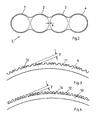
- FIG. 1 a sleeve package consisting of 4 rough-cast sleeves, for use in a four-cylinder engine,
- FIG. 2 the rough-cast sleeve package according to FIG. 1 in a top view
- FIGS. 3 , 4 enlarged cross-sections through parts of the sleeve wall, with configuration possibilities of its surface roughness
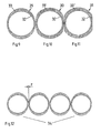
- FIGS. 5-7 configurations of rough-cast sleeves with a variable sleeve wall thickness and constant depth of the roughened region
- FIG. 8 an arrangement of 4 rough-cast sleeves having an elliptical outside contour, according to FIG. 5 , for use in a four-cylinder engine,
- FIGS. 9-11 configurations of rough-cast sleeves having a constant sleeve wall thickness and variable depth of the roughened region
- FIG. 12 an arrangement of 4 rough-cast sleeves having an elliptical outside contour, according to FIG. 9 , for use in a four-cylinder engine,
- FIGS. 13-15 configurations of flattcncd rough-cast sleeves having a variable sleeve wall thickness, constant depth of the roughened region, and without rough-cast structures on the outer surfaces of those sleeve regions that lie opposite one another in the case of the rough-cast sleeves combined to form sleeve packages,
- FIG. 16 two rough-cast sleeves joined together
- FIG. 17 two rough-cast sleeves joined together using two bridges
- FIG. 18 a configuration of a bridge for joining rough-cast sleeves
- FIG. 19 another configuration of a bridge for joining rough-cast sleeves
- FIG. 20-24 rough-cast sleeves having one flattened region each, which has a step in its lower region
- FIG. 25 two rough-cast sleeves joined together, having a spacer between the flattened regions
- FIG. 26 an enlarged representation of the spacer according to FIG. 25 .
- FIG. 1 shows, in a perspective view
- FIG. 2 shows, in a top view, a sleeve package 5 consisting of four rough-cast sleeves 1 to 4 .
- the 4 rough-cast sleeves 1 to 4 have roughened outer surfaces over their entire axial length.
- the common wall regions 6 to 8 of adjacent sleeves 1 to 4 have a land width x that corresponds to the other wall thickness of the rough-cast sleeves 1 to 4 .
- the entire sleeve package 5 is produced in a single casting process, from an aluminum-silicon alloy, whereby the gravity casting method or the “lost-foam” casting method is used. Both of these casting methods are known from the state of the art (see DE 199 58 185 A1 with regard to the “lost-foam” casting method), and will not be explained in greater detail here.
- the entire sleeve package 5 is set into the casting mold provided for this purpose, and casting material is cast around it.
- the elevations 10 and 11 are shaped in such a manner that undercuts 13 and 14 are formed by them, the function of which consists in anchoring the rough-cast sleeves in the casting material of the engine block.
- the height of the elevations 11 and 12 and thereby the depth y of the roughened region have a value of 0.2 to 2 mm.
- the rough-cast sleeves shown in cross-section in FIGS. 5 to 15 have two contact regions that lie opposite one another and reach over their entire axial length.
- the contact regions are regions where the rough-cast sleeves contact each other.
- the radially outer surface of the contact regions have a lesser radial distance from the longitudinal axes of the sleeves than the radially outer surface of the other two regions.
- the rough cast sleeves can consist of cast iron and are then preferably produced using the spin casting method. However, they can also consist of an aluminum-silicon alloy, which opens up the possibility of producing the rough-cast sleeves using the gravity casting method, the spin casting method, or the “lost-foam” casting method.
- the sleeves can already obtain their final shape, within the framework of the casting process.
- there is also the possibility of shaping the sleeves after casting such as shown in FIGS. 5-15 , by means of mechanical machining (milling).
- an engine block from light metal, such as, for example, from aluminum, magnesium, or an alloy of these metals
- the sleeves can be joined to one another by way of their contact regions, i.e. welded, soldered, or glued to one another by way of the mantle surfaces of the contact area, so that eyeglass-shaped arrangements of the sleeves result, in cross-section.
- the sleeve packages obtained in this manner are then laid into the casting mold and the light metal of the engine block is cast around them.
- FIG. 5 A sleeve 15 having an elliptical outer shape in cross-section, variable thickness of the sleeve wall 19 , and constant depth of the roughened region 20 is shown.
- FIG. 6 A sleeve 16 having a variable thickness of the sleeve wall 19 ′, with a constant depth of the roughened region 20 , and an outer shape that consists of four arc-shaped segments 21 to 24 of approximately equal size, whereby thicker regions of the sleeve wall 19 ′ delimit the segments 21 and 22 that lie opposite one another, and thinner regions of the sleeve wall 19 ′, delimit the segments 23 and 24 that lie opposite one another, towards the outside, is shown.
- FIG. 7 A sleeve 17 having a variable thickness of the sleeve wall 19 ′′, with a constant depth of the roughened region 20 and an outer shape that is composed, in cross-section, of two arc-shaped segments 25 and 26 that lie opposite one another, and two contact segments 27 and 28 that like opposite one another, is shown.
- the contact regions of the sleeve 17 that lie opposite one another are delimited, towards the outside, by the segments 27 and 28 .
- FIG. 8 shows a possibility of disposing the rough-cast sleeves 15 having an elliptical contour next to one another, in space-saving manner, so that a sleeve package 18 that is suitable for a four-cylinder engine is obtained.
- the regions of the elliptical contour next to the axis delimit the contact regions of the sleeves 15 , which regions lie at a distance opposite one another in the arrangement of the sleeves 15 to form a sleeve package 18 .
- FIG. 9 A sleeve 29 having a constant thickness of the sleeve wall 32 , with a variable depth of the roughened region 33 and with an elliptical outer contour in cross-section, which is the same as the outer shape of the sleeve 15 according to FIG. 5 , is shown.
- FIG. 10 A sleeve 30 having a constant thickness of the sleeve wall 32 , with a variable depth of the roughened region 33 ′, and with an outer contour consisting of two arc-shaped segments, in cross-section, which contour is the same as the outer shape of the sleeve 16 according to FIG. 6 , is shown.
- FIG. 11 A sleeve 31 having a constant thickness of the sleeve wall 32 , with a variable depth of the roughened region 33 ′′, and an outer contour formed from two arc-shaped segments and two flat segments, which lie opposite one another, in each instance, which contour is the same as the outer shape of the sleeve 17 shown in FIG. 7 , is shown.
- the rough-cast sleeves 29 to 31 shown in FIG. 9 to 11 are produced using the spin casting method, whereby the variation of the depth of the roughened regions 33 , 33 ′, and 33 ′′ can be achieved by means of a corresponding adjustment of the process parameters.
- FIG. 12 shows an arrangement of 4 of the rough-cast sleeves 29 shown in FIG. 9 to form a sleeve package 34 similar to the sleeve package 18 shown in FIG. 8 , for use in a four-cylinder engine.
- the rough-cast sleeves of the type shown can be disposed at a distance z of 0.5 to 0.05 mm next to one another.
- FIG. 13 A sleeve 35 having a variable sleeve wall thickness, constant depth of the roughened region, and an elliptical outer contour, which is the same as the outer contour of the sleeve 15 shown in FIG. 5 , is shown.
- the contact sleeve regions 38 and 39 that lie opposite one another do not have any rough-cast structures.
- FIG. 14 A sleeve 36 having a variable sleeve wall thickness, constant depth of the roughened region, and an outer contour consisting of several arc-shaped segments, in cross-section, which contour is the same as the outer shape of the sleeve 16 shown in FIG. 6 , is shown.
- the contact sleeve regions 40 and 41 that lie opposite one another do not have any rough-cast structures.
- FIG. 15 A sleeve 37 having a variable sleeve wall thickness, constant depth of the roughened region, and an outer contour consisting of two arc-shaped and two flat segments, in cross-section, which contour is the same as the outer shape of the sleeve 17 shown in FIG. 7 , is shown.
- a flat segment 43 of the outer contour can be provided with a rough-cast structure, and the segment 42 that lies opposite the former can be configured without a rough-cast structure.
- those segments 38 to 42 of the outer contours of the rough-cast sleeves 35 to 37 that have no rough-cast structures can already be produced within the framework of the casting process.
- the sleeves 17 , 31 , and 37 shown in FIGS. 7 , 11 , and 15 can be joined to one another by way of these segments, by means of gluing, soldering, or welding, so that sleeve structures that are eyeglass-shaped in cross-section result.
- a glue or solder layer 44 is applied to the opposite region of the sleeves, in this connection, before the sleeves are joined together.
- FIG. 17 Another possibility of connecting sleeves with one another before they are cast into an engine block is shown in FIG. 17 .
- bridges 45 and 46 are used, which are glued or soldered onto adjacent regions of the faces 47 and 48 , i.e. 49 and 50 of the sleeves 51 and 52 , respectively, and thereby connect the sleeves 51 and 52 .
- the bridges 45 , 46 can have the shape of round disks. According to FIG. 19 , however, the bridges 45 ′, 46 ′ can also be given the shape of rectangular slices.
- the bridges are produced from light metal or from a light metal alloy.
- the gap between the sleeves cannot be at just any desired value of narrowness, so that the light metal of the engine block flows through the gap between the sleeves, fills the space between the sleeves, and creates a firm connection between the sleeves after having cooled. If sleeves are flattened on opposite mantle regions, it is necessary, for this purpose, to ensure that the sleeves always assume a clearly defined position of rotation when mounted on the spindle sleeves, so that the gap between the flattened regions of the sleeves maintains its maximal width and is not reduced in size or completely closed off by sleeves that have been partially turned.
- the flattened regions of the sleeve mantle surfaces that lie opposite one another have steps 53 , 53 ′ in their lower regions, facing the crankshaft, which steps are shown in a side view in FIGS. 20 , 23 , and 24 , and in a top view in FIGS. 21 and 22 .
- the steps 53 , 53 ′ also have flattened regions 54 , 54 ′ ( FIGS. 20 , 23 , 24 ), which must be oriented parallel to one another when the sleeves are pushed onto spindle sleeves, so that the sleeves fit onto the spindle sleeves, and which thereby ensure that the sleeves always assume a clearly defined position of rotation relative to one another.
- the sleeves can be joined to one another, i.e. glued or soldered to one another, by way of the flattened regions 54 , 54 ′ of the steps 53 , 53 ′.
- the width of the gap 55 is 1 mm to 3.5 m in the case of a rough-cast sleeve having a wall thickness 56 of 2.5 mm and a depth 57 of the roughened region of 1.5 mm.
- the land width 60 is 5.5 mm in the case of sleeves having a cylinder diameter 58 of 82 mm. In this connection, a cylinder distance 59 of 87.5 mm can be achieved.
- the flattened region 61 formed into the sleeve mantle surface can be seen well in a side view, and in FIG. 24 , it can be seen well in a top view; in contrast to the remaining sleeve mantle surface, it does not have any roughened region.
- Another solution for the problem of keeping the contact areas of the rough-cast sleeves at a distance and of ensuring that the sleeves are disposed in a clearly defined position of rotation relative to one another consists, according to FIGS. 25 and 26 , of a spacer 62 disposed between the contact regions 63 and 64 .
- This has the additional advantage that space is available between the contact regions 63 and 64 of the sleeves being held at a distance from one another, for cooling bores to be made in the engine block.
- regions of the outer surfaces of sleeves disposed next to one another, which surfaces lie opposite one another, can be configured in concave manner.
Abstract
Description
- x land width
- y depth of the roughened region
- z distance between two rough-cast sleeves
- 1 to 4 rough-cast sleeve
- 5 sleeve package
- 6 to 8 wall region
- 9, 10 cross-section
- 11, 12 elevation
- 13, 14 undercut
- 15 to 17 sleeve, cylinder sleeve
- 18 sleeve package
- 19, 19′ 19″ sleeve wall
- 20 roughened region
- 21 to 24 segment of the outer shape of the
sleeve 16 - 25 to 28 segment of the outer shape of the
sleeve 17 - 29 to 31 sleeve, cylinder sleeve
- 32 sleeve wall
- 33, 33′, 33″ roughened region
- 34 sleeve package
- 35 to 37 sleeve, cylinder sleeve
- 38, 39 contact region of the
sleeve 35 - 40, 41 contact region of the
sleeve 36 - 42, 43 segment of the outer contour of the
sleeve 37 - 44 adhesive or solder layer
- 45, 45′, 46, 46′ bridge
- 47 to 50 face
- 51, 52 sleeve, cylinder sleeve
- 53, 53′ step
- 55, 54′ flattened region of the
step 53 - 55 gap width
- 56 wall thickness
- 57 depth of the roughened region
- 58 cylinder diameter
- 60 land width
- 61 contact region
- 62 spacer
- 63, 64 contact region
Claims (3)
Applications Claiming Priority (3)
| Application Number | Priority Date | Filing Date | Title |
|---|---|---|---|
| DE102004007774A DE102004007774A1 (en) | 2004-02-18 | 2004-02-18 | Bushing for an internal combustion engine |
| DE102004007774.6 | 2004-02-18 | ||
| PCT/DE2005/000283 WO2005078265A1 (en) | 2004-02-18 | 2005-02-18 | Cylinder sleeve for an internal combustion engine |
Publications (2)
| Publication Number | Publication Date |
|---|---|
| US20070209627A1 US20070209627A1 (en) | 2007-09-13 |
| US7806098B2 true US7806098B2 (en) | 2010-10-05 |
Family
ID=34853501
Family Applications (1)
| Application Number | Title | Priority Date | Filing Date |
|---|---|---|---|
| US10/589,792 Expired - Fee Related US7806098B2 (en) | 2004-02-18 | 2005-02-18 | Cylinder sleeve for an internal combustion engine |
Country Status (8)
| Country | Link |
|---|---|
| US (1) | US7806098B2 (en) |
| EP (1) | EP1721072B1 (en) |
| JP (1) | JP4653762B2 (en) |
| KR (1) | KR101279846B1 (en) |
| CN (1) | CN2900814Y (en) |
| BR (1) | BRPI0507731A (en) |
| DE (1) | DE102004007774A1 (en) |
| WO (1) | WO2005078265A1 (en) |
Cited By (8)
| Publication number | Priority date | Publication date | Assignee | Title |
|---|---|---|---|---|
| US20130160964A1 (en) * | 2011-12-22 | 2013-06-27 | Magna BDW technologies GmbH | Process for producing cylindrical components |
| US20170314501A1 (en) * | 2016-04-27 | 2017-11-02 | Mahle International Gmbh | Rough cast cylinder liner |
| US10247129B2 (en) | 2017-02-22 | 2019-04-02 | GM Global Technology Operations LLC | Cylinder liner for internal combustion engine |
| US10253721B2 (en) | 2017-04-12 | 2019-04-09 | GM Global Technology Operations LLC | Cylinder liner for internal combustion engine |
| US20190323448A1 (en) * | 2018-04-19 | 2019-10-24 | GM Global Technology Operations LLC | Cylinder liner for internal combustion engine and method for making cylinder liner |
| US10876494B2 (en) | 2018-08-22 | 2020-12-29 | Tpr Co., Ltd. | Cylinder liner, block manufacturing method and cylinder liner manufacturing method |
| US10895218B2 (en) | 2019-02-01 | 2021-01-19 | Caterpillar Inc. | Liner for engine cylinder with lower liner support |
| US11480131B2 (en) | 2018-09-17 | 2022-10-25 | GM Global Technology Operations LLC | Engine block for an internal combustion engine |
Families Citing this family (22)
| Publication number | Priority date | Publication date | Assignee | Title |
|---|---|---|---|---|
| WO2008111559A1 (en) * | 2007-03-15 | 2008-09-18 | Honda Motor Co., Ltd. | Hollow member, cylinder sleeve and methods for producing them |
| DE102007041010A1 (en) * | 2007-08-29 | 2009-03-05 | Mahle International Gmbh | Cylinder crankcase for an internal combustion engine |
| JP5276530B2 (en) * | 2009-06-24 | 2013-08-28 | 日本ピストンリング株式会社 | Dry cylinder liner for internal combustion engines |
| DE102009043566A1 (en) * | 2009-09-30 | 2011-04-07 | Mahle International Gmbh | Cylinder crankcase for use in internal combustion engine of motor vehicle, has cylinder liner or assembly comprising outer shell surface with axial area surrounded by chamber, where lower area of surface is connected with crankcase casting |
| JP5572847B2 (en) | 2010-03-17 | 2014-08-20 | 株式会社Moresco | Cylinder liner and manufacturing method thereof |
| DE102010047325B4 (en) * | 2010-10-01 | 2021-11-18 | Daimler Ag | Internal combustion engine with a cylinder housing made of light metal cast and with cylinder liners made of rough cast |
| DE102011085476A1 (en) * | 2011-10-28 | 2013-05-02 | Ks Kolbenschmidt Gmbh | Functionally optimized design of a cylinder liner |
| CN103016723B (en) | 2012-11-29 | 2016-08-03 | 广东肇庆动力金属股份有限公司 | A kind of aluminum contains the preparation method of cylinder jacket |
| KR101509749B1 (en) * | 2013-11-27 | 2015-04-07 | 현대자동차 주식회사 | Engine having cylinder block |
| BR102013031969A8 (en) * | 2013-12-12 | 2015-12-15 | Mahle Int Gmbh | cylinder liner of an internal combustion engine |
| US10094325B2 (en) * | 2014-01-28 | 2018-10-09 | ZYNP International Corp. | Cylinder liner |
| CN105020010B (en) * | 2014-04-29 | 2018-09-07 | 长城汽车股份有限公司 | Engine and vehicle with the engine |
| CN105020046B (en) * | 2014-04-29 | 2017-10-13 | 长城汽车股份有限公司 | For the body group of engine and the engine with the body group |
| DE102014015089A1 (en) * | 2014-10-11 | 2016-04-14 | Daimler Ag | Crankcase and method for its production |
| JP2016089744A (en) * | 2014-11-06 | 2016-05-23 | スズキ株式会社 | Cylinder sleeve |
| DE102015201994A1 (en) * | 2015-02-05 | 2016-08-11 | Ford Global Technologies, Llc | Reciprocating engine, motor vehicle |
| JP6610423B2 (en) * | 2016-05-17 | 2019-11-27 | スズキ株式会社 | Casting parts |
| KR101927284B1 (en) * | 2017-11-17 | 2018-12-10 | 티피알 가부시키가이샤 | Cast iron cylindrical member and composite structure |
| CN110857671B (en) * | 2018-08-22 | 2022-03-08 | 帝伯爱尔株式会社 | Cylinder liner, method for manufacturing engine block, and method for manufacturing cylinder liner |
| JP6657341B2 (en) | 2018-08-22 | 2020-03-04 | Tpr株式会社 | Cylinder liner, block manufacturing method, and cylinder liner manufacturing method |
| CN110894813B (en) * | 2018-08-22 | 2023-05-02 | 帝伯爱尔株式会社 | Cylinder liner, method for manufacturing the same, and method for manufacturing cylinder block using the same |
| KR102494359B1 (en) | 2020-11-23 | 2023-02-07 | 한국철도기술연구원 | Cooling structure for driver built-in motor |
Citations (30)
| Publication number | Priority date | Publication date | Assignee | Title |
|---|---|---|---|---|
| US2810378A (en) * | 1955-06-22 | 1957-10-22 | Gen Motors Corp | Cylinder block and method of making the same |
| DE1576437A1 (en) | 1967-11-17 | 1970-01-22 | Zuendapp Werke Gmbh | Light metal cylinder with cast barrel |
| DE2438762A1 (en) | 1974-08-13 | 1976-03-04 | Mahle Gmbh | LIQUID-COOLED CYLINDER LUBRICATION FOR RECEPTACLE COMBUSTION MACHINES |
| US4127058A (en) * | 1974-08-13 | 1978-11-28 | Mahle Gmbh | Liquid-cooled cylinder sleeves |
| US4419971A (en) * | 1979-11-21 | 1983-12-13 | Tokyo Shibaura Denki Kabushiki Kaisha | Cylinder liner for an internal combustion engine |
| EP0110406A2 (en) | 1982-12-01 | 1984-06-13 | Nissan Motor Co., Ltd. | Improved cylinder block for internal combustion engine |
| US4616603A (en) * | 1982-09-10 | 1986-10-14 | M.A.N. Nutzfahrzeuge Gmbh | Cylinder liner for a multi-cylinder internal combustion engine and an engine block therefor |
| US4630345A (en) * | 1983-03-24 | 1986-12-23 | Sachs-Systemtechnik Gmbh | Method for manufacturing a cylinder unit for a cylinder piston combustion engine |
| US4903652A (en) * | 1989-07-31 | 1990-02-27 | Ford Motor Company | Cylinder liner insert and method of making engine block therewith |
| US5732671A (en) * | 1995-11-29 | 1998-03-31 | Toyota Jidosha Kabushiki Kaisha | Method and apparatus for manufacturing cylinder blocks |
| EP0837235A1 (en) | 1996-10-16 | 1998-04-22 | Toyota Jidosha Kabushiki Kaisha | An internal combustion engine cylinder block and manufacturing method |
| DE19807685A1 (en) | 1998-02-25 | 1999-09-09 | Daimler Chrysler Ag | Method for producing a blank of a cylinder liner to be poured into a light metal crankcase of a lifting crank machine |
| DE19857390C1 (en) | 1998-12-12 | 2000-04-06 | Daimler Chrysler Ag | Method of making crankcase for internal combustion engine involves heating and cooling the liner to crankcase joints during manufacture |
| US6182629B1 (en) * | 1998-10-02 | 2001-02-06 | Federal-Mogul Burscheid Gmbh | Method of making a cylinder liner |
| DE19937934A1 (en) | 1999-08-11 | 2001-02-15 | Bayerische Motoren Werke Ag | Cylinder crankcase, method for manufacturing the cylinder liners therefor and method for manufacturing the cylinder crankcase with these cylinder liners |
| DE19958185A1 (en) | 1999-12-02 | 2001-06-07 | Mahle Ventiltrieb Gmbh | Lost form for the production of a cylinder liner |
| DE10009135A1 (en) | 2000-02-26 | 2001-08-30 | Volkswagen Ag | Bushing sleeve is made of aluminum alloy for casting in cylindrical blocks made of light metal having an outer cast surface in the region of its runner in the block |
| DE10103459A1 (en) | 2001-01-25 | 2001-09-06 | Volkswagen Ag | Automotive crankcase and liner production involves roughening liner surface facing crankcase during casting by using hypereutectoid aluminum alloy liner and hypoeutectoid crankcase. |
| US6298818B1 (en) * | 2000-02-16 | 2001-10-09 | Kabushiki Kaisha Koyama | Cylinder liner and cylinder block and method of manufacturing the same |
| JP2002097998A (en) | 2000-09-21 | 2002-04-05 | Toyota Motor Corp | Liner for insert and method of manufacturing cylinder block |
| US20030000086A1 (en) * | 2000-02-10 | 2003-01-02 | Antonio Fuganti | Method for producing a cylinder block for an internal combustion engine |
| DE10147219A1 (en) | 2001-09-24 | 2003-04-17 | Daimler Chrysler Ag | Cylinder liner of an internal combustion engine |
| US6557513B1 (en) * | 2001-09-28 | 2003-05-06 | Dana Corporation | Cylinder liner with reduced wall thickness on piston pin axis |
| US20030084567A1 (en) * | 2001-10-16 | 2003-05-08 | Thomas Dickmann | Method for profiling the outer circumferential face of cylinder liners |
| DE10235910A1 (en) | 2002-08-06 | 2004-02-26 | Peak-Werkstoff Gmbh | Combustion engine cylinder liner set casting joins liners in sequence by side welds and includes cooling channels in liners all arranged at spacing matching cylinder bore interval. |
| WO2004074667A1 (en) * | 2003-01-28 | 2004-09-02 | Honda Motor Co., Ltd. | Cylinder block and cylinder sleeve, method of producing cylinder block and cylinder sleeve by friction stir welding, and friction stir welding method |
| US20050150476A1 (en) * | 2002-08-06 | 2005-07-14 | Uwe Gohrbandt | Combination of cylinder liners consisting of a light metal alloy |
| US6920859B2 (en) * | 2003-07-10 | 2005-07-26 | Hyundai Motor Company | Cylinder liner |
| US20050161014A1 (en) * | 2003-12-25 | 2005-07-28 | Mitsubishi Jidosha Kogyo Kabushiki Kaisha | Engine cylinder liner construction |
| US7226667B2 (en) * | 2002-05-13 | 2007-06-05 | Honda Giken Kogyo Kabushiki Kaisha | Cast-iron insert and method of manufacturing same |
Family Cites Families (6)
| Publication number | Priority date | Publication date | Assignee | Title |
|---|---|---|---|---|
| IT1240746B (en) * | 1990-04-06 | 1993-12-17 | Temav Spa | PROCEDURE FOR OBTAINING A CONTINUOUS METALLURGIC LINK BETWEEN CYLINDER BARRELS ID THE JET CONSTITUTING THE BASE OF AN INTERNAL COMBUSTION ENGINE |
| EP0704613A1 (en) * | 1994-09-28 | 1996-04-03 | KS Aluminium Technologie Aktiengesellschaft | Compositely cast cylinder or cylinderblock |
| JPH0979085A (en) * | 1995-09-12 | 1997-03-25 | Mitsubishi Automob Eng Co Ltd | Cylinder block for internal combustion engine |
| JPH1030494A (en) * | 1996-07-15 | 1998-02-03 | Toyota Motor Corp | Cylinder block |
| JP3800510B2 (en) * | 2001-11-22 | 2006-07-26 | 株式会社豊田自動織機 | Powder compact, method for producing the same, and method for producing a porous sintered body |
| JP4210468B2 (en) * | 2002-05-13 | 2009-01-21 | 本田技研工業株式会社 | Cast iron cast-in member |
-
2004
- 2004-02-18 DE DE102004007774A patent/DE102004007774A1/en not_active Withdrawn
-
2005
- 2005-02-18 CN CNU200590000003XU patent/CN2900814Y/en not_active Expired - Lifetime
- 2005-02-18 WO PCT/DE2005/000283 patent/WO2005078265A1/en active Application Filing
- 2005-02-18 EP EP05714992.4A patent/EP1721072B1/en not_active Expired - Fee Related
- 2005-02-18 KR KR1020067016912A patent/KR101279846B1/en active IP Right Grant
- 2005-02-18 BR BRPI0507731-1A patent/BRPI0507731A/en not_active Application Discontinuation
- 2005-02-18 JP JP2006553431A patent/JP4653762B2/en not_active Expired - Fee Related
- 2005-02-18 US US10/589,792 patent/US7806098B2/en not_active Expired - Fee Related
Patent Citations (36)
| Publication number | Priority date | Publication date | Assignee | Title |
|---|---|---|---|---|
| US2810378A (en) * | 1955-06-22 | 1957-10-22 | Gen Motors Corp | Cylinder block and method of making the same |
| DE1576437A1 (en) | 1967-11-17 | 1970-01-22 | Zuendapp Werke Gmbh | Light metal cylinder with cast barrel |
| DE2438762A1 (en) | 1974-08-13 | 1976-03-04 | Mahle Gmbh | LIQUID-COOLED CYLINDER LUBRICATION FOR RECEPTACLE COMBUSTION MACHINES |
| US4127058A (en) * | 1974-08-13 | 1978-11-28 | Mahle Gmbh | Liquid-cooled cylinder sleeves |
| US4419971A (en) * | 1979-11-21 | 1983-12-13 | Tokyo Shibaura Denki Kabushiki Kaisha | Cylinder liner for an internal combustion engine |
| US4616603A (en) * | 1982-09-10 | 1986-10-14 | M.A.N. Nutzfahrzeuge Gmbh | Cylinder liner for a multi-cylinder internal combustion engine and an engine block therefor |
| EP0110406A2 (en) | 1982-12-01 | 1984-06-13 | Nissan Motor Co., Ltd. | Improved cylinder block for internal combustion engine |
| US4630345A (en) * | 1983-03-24 | 1986-12-23 | Sachs-Systemtechnik Gmbh | Method for manufacturing a cylinder unit for a cylinder piston combustion engine |
| US4903652A (en) * | 1989-07-31 | 1990-02-27 | Ford Motor Company | Cylinder liner insert and method of making engine block therewith |
| US5732671A (en) * | 1995-11-29 | 1998-03-31 | Toyota Jidosha Kabushiki Kaisha | Method and apparatus for manufacturing cylinder blocks |
| EP0837235A1 (en) | 1996-10-16 | 1998-04-22 | Toyota Jidosha Kabushiki Kaisha | An internal combustion engine cylinder block and manufacturing method |
| US6286210B1 (en) | 1998-02-25 | 2001-09-11 | Daimlerchrysler Ag | Method for producing a cylinder liner blank to be cast into a light-alloy crankcase of a reciprocating engine |
| DE19807685A1 (en) | 1998-02-25 | 1999-09-09 | Daimler Chrysler Ag | Method for producing a blank of a cylinder liner to be poured into a light metal crankcase of a lifting crank machine |
| US6182629B1 (en) * | 1998-10-02 | 2001-02-06 | Federal-Mogul Burscheid Gmbh | Method of making a cylinder liner |
| DE19857390C1 (en) | 1998-12-12 | 2000-04-06 | Daimler Chrysler Ag | Method of making crankcase for internal combustion engine involves heating and cooling the liner to crankcase joints during manufacture |
| DE19937934A1 (en) | 1999-08-11 | 2001-02-15 | Bayerische Motoren Werke Ag | Cylinder crankcase, method for manufacturing the cylinder liners therefor and method for manufacturing the cylinder crankcase with these cylinder liners |
| US20020033161A1 (en) | 1999-08-11 | 2002-03-21 | Dietmar Hoffmann | Cylinder crankcase, procedure for manufacturing the cylinder bushings for the cylinder crankcase, and procedure for manufacturing the cylinder crankcase with these cylinder bushings |
| DE19958185A1 (en) | 1999-12-02 | 2001-06-07 | Mahle Ventiltrieb Gmbh | Lost form for the production of a cylinder liner |
| US6802121B2 (en) | 2000-02-10 | 2004-10-12 | C.R.F. Societa Consortile Per Azioni | Method for producing a cylinder block for an internal combustion engine |
| US20030000086A1 (en) * | 2000-02-10 | 2003-01-02 | Antonio Fuganti | Method for producing a cylinder block for an internal combustion engine |
| US6298818B1 (en) * | 2000-02-16 | 2001-10-09 | Kabushiki Kaisha Koyama | Cylinder liner and cylinder block and method of manufacturing the same |
| DE10009135A1 (en) | 2000-02-26 | 2001-08-30 | Volkswagen Ag | Bushing sleeve is made of aluminum alloy for casting in cylindrical blocks made of light metal having an outer cast surface in the region of its runner in the block |
| JP2002097998A (en) | 2000-09-21 | 2002-04-05 | Toyota Motor Corp | Liner for insert and method of manufacturing cylinder block |
| DE10103459A1 (en) | 2001-01-25 | 2001-09-06 | Volkswagen Ag | Automotive crankcase and liner production involves roughening liner surface facing crankcase during casting by using hypereutectoid aluminum alloy liner and hypoeutectoid crankcase. |
| DE10147219A1 (en) | 2001-09-24 | 2003-04-17 | Daimler Chrysler Ag | Cylinder liner of an internal combustion engine |
| US6640765B2 (en) | 2001-09-24 | 2003-11-04 | Daimlerchrysler Ag | Cylinder liner of an internal combustion engine |
| US6557513B1 (en) * | 2001-09-28 | 2003-05-06 | Dana Corporation | Cylinder liner with reduced wall thickness on piston pin axis |
| US20030084567A1 (en) * | 2001-10-16 | 2003-05-08 | Thomas Dickmann | Method for profiling the outer circumferential face of cylinder liners |
| US6748655B2 (en) * | 2001-10-16 | 2004-06-15 | Peak Werkstoff Gmbh | Method for profiling the outer circumferential face of cylinder liners |
| US7226667B2 (en) * | 2002-05-13 | 2007-06-05 | Honda Giken Kogyo Kabushiki Kaisha | Cast-iron insert and method of manufacturing same |
| DE10235910A1 (en) | 2002-08-06 | 2004-02-26 | Peak-Werkstoff Gmbh | Combustion engine cylinder liner set casting joins liners in sequence by side welds and includes cooling channels in liners all arranged at spacing matching cylinder bore interval. |
| US20050150476A1 (en) * | 2002-08-06 | 2005-07-14 | Uwe Gohrbandt | Combination of cylinder liners consisting of a light metal alloy |
| WO2004074667A1 (en) * | 2003-01-28 | 2004-09-02 | Honda Motor Co., Ltd. | Cylinder block and cylinder sleeve, method of producing cylinder block and cylinder sleeve by friction stir welding, and friction stir welding method |
| US7392771B2 (en) * | 2003-01-28 | 2008-07-01 | Honda Motor Co., Ltd. | Cylinder block and cylinder sleeve, method of producing cylinder block and cylinder sleeve by friction stir welding, and friction stir welding method |
| US6920859B2 (en) * | 2003-07-10 | 2005-07-26 | Hyundai Motor Company | Cylinder liner |
| US20050161014A1 (en) * | 2003-12-25 | 2005-07-28 | Mitsubishi Jidosha Kogyo Kabushiki Kaisha | Engine cylinder liner construction |
Cited By (14)
| Publication number | Priority date | Publication date | Assignee | Title |
|---|---|---|---|---|
| US20130160964A1 (en) * | 2011-12-22 | 2013-06-27 | Magna BDW technologies GmbH | Process for producing cylindrical components |
| US8978733B2 (en) * | 2011-12-22 | 2015-03-17 | Magna BDW technologies GmbH | Process for producing cylindrical components |
| US10465627B2 (en) * | 2016-04-27 | 2019-11-05 | Mahle International Gmbh | Rough cast cylinder liner |
| CN107313869A (en) * | 2016-04-27 | 2017-11-03 | 马勒国际有限公司 | Coarse cylinder liner |
| US20180245537A1 (en) * | 2016-04-27 | 2018-08-30 | Mahle International Gmbh | Rough cast cylinder liner |
| US10215128B2 (en) * | 2016-04-27 | 2019-02-26 | Mahle International Gmbh | Rough cast cylinder liner |
| US20170314501A1 (en) * | 2016-04-27 | 2017-11-02 | Mahle International Gmbh | Rough cast cylinder liner |
| CN107313869B (en) * | 2016-04-27 | 2021-06-04 | 马勒国际有限公司 | Rough cylinder liner |
| US10247129B2 (en) | 2017-02-22 | 2019-04-02 | GM Global Technology Operations LLC | Cylinder liner for internal combustion engine |
| US10253721B2 (en) | 2017-04-12 | 2019-04-09 | GM Global Technology Operations LLC | Cylinder liner for internal combustion engine |
| US20190323448A1 (en) * | 2018-04-19 | 2019-10-24 | GM Global Technology Operations LLC | Cylinder liner for internal combustion engine and method for making cylinder liner |
| US10876494B2 (en) | 2018-08-22 | 2020-12-29 | Tpr Co., Ltd. | Cylinder liner, block manufacturing method and cylinder liner manufacturing method |
| US11480131B2 (en) | 2018-09-17 | 2022-10-25 | GM Global Technology Operations LLC | Engine block for an internal combustion engine |
| US10895218B2 (en) | 2019-02-01 | 2021-01-19 | Caterpillar Inc. | Liner for engine cylinder with lower liner support |
Also Published As
| Publication number | Publication date |
|---|---|
| EP1721072B1 (en) | 2017-04-05 |
| KR101279846B1 (en) | 2013-06-28 |
| KR20060129027A (en) | 2006-12-14 |
| EP1721072A1 (en) | 2006-11-15 |
| CN2900814Y (en) | 2007-05-16 |
| BRPI0507731A (en) | 2007-07-10 |
| US20070209627A1 (en) | 2007-09-13 |
| WO2005078265A1 (en) | 2005-08-25 |
| JP2007524787A (en) | 2007-08-30 |
| DE102004007774A1 (en) | 2005-09-15 |
| JP4653762B2 (en) | 2011-03-16 |
Similar Documents
| Publication | Publication Date | Title |
|---|---|---|
| US7806098B2 (en) | Cylinder sleeve for an internal combustion engine | |
| RU2376488C2 (en) | Cylinder sleeve (versions) and engine | |
| US5005469A (en) | Cylinder liner unit for use in an internal combustion engine | |
| US5979298A (en) | Cooling gallery for pistons | |
| JP6521958B2 (en) | Cylinder liner with tie layer | |
| JP4224725B1 (en) | Cylinder block and manufacturing method thereof | |
| JP3825732B2 (en) | Internal combustion engine cylinder liner | |
| JPS5854901B2 (en) | Camshaft manufacturing method and device | |
| US9903309B2 (en) | Welded piston assembly | |
| BRPI0612791A2 (en) | cylinder liner and method to manufacture it | |
| US6748655B2 (en) | Method for profiling the outer circumferential face of cylinder liners | |
| US20050150476A1 (en) | Combination of cylinder liners consisting of a light metal alloy | |
| US8720319B2 (en) | Cylinder sleeve | |
| US4709621A (en) | Internal combustion engine piston and a method of producing the same | |
| JP4746874B2 (en) | Light alloy cylinder liner composition | |
| JP2005534498A (en) | Cast joint of hollow shape made of light metal alloy | |
| JP2004508501A (en) | Pistons for internal combustion engines | |
| KR19980081095A (en) | Cylinder crank housing with welded bridge | |
| JP5470049B2 (en) | Cylinder crank housing manufacturing method having a plurality of cylinder sleeves and a short cylinder sleeve to which a material strip is fixed | |
| JPS6132161Y2 (en) | ||
| JPS62130725A (en) | Production of hollow assembly cam shaft | |
| JPH0335863A (en) | Structure of cylinder block for engine | |
| JPH01186260A (en) | Manufacture of bearing of engine | |
| JPS6359020B2 (en) | ||
| JP2007511696A (en) | Internal combustion engine component and method for manufacturing the same |
Legal Events
| Date | Code | Title | Description |
|---|---|---|---|
| STCF | Information on status: patent grant |
Free format text: PATENTED CASE |
|
| REMI | Maintenance fee reminder mailed | ||
| FPAY | Fee payment |
Year of fee payment: 4 |
|
| SULP | Surcharge for late payment | ||
| MAFP | Maintenance fee payment |
Free format text: PAYMENT OF MAINTENANCE FEE, 8TH YEAR, LARGE ENTITY (ORIGINAL EVENT CODE: M1552) Year of fee payment: 8 |
|
| FEPP | Fee payment procedure |
Free format text: MAINTENANCE FEE REMINDER MAILED (ORIGINAL EVENT CODE: REM.); ENTITY STATUS OF PATENT OWNER: LARGE ENTITY |
|
| LAPS | Lapse for failure to pay maintenance fees |
Free format text: PATENT EXPIRED FOR FAILURE TO PAY MAINTENANCE FEES (ORIGINAL EVENT CODE: EXP.); ENTITY STATUS OF PATENT OWNER: LARGE ENTITY |
|
| STCH | Information on status: patent discontinuation |
Free format text: PATENT EXPIRED DUE TO NONPAYMENT OF MAINTENANCE FEES UNDER 37 CFR 1.362 |
|
| FP | Lapsed due to failure to pay maintenance fee |
Effective date: 20221005 |