US7806027B1 - Torque limiter wrench and method - Google Patents
Torque limiter wrench and method Download PDFInfo
- Publication number
- US7806027B1 US7806027B1 US11/983,996 US98399607A US7806027B1 US 7806027 B1 US7806027 B1 US 7806027B1 US 98399607 A US98399607 A US 98399607A US 7806027 B1 US7806027 B1 US 7806027B1
- Authority
- US
- United States
- Prior art keywords
- handle
- jaw
- torque
- cam
- axis
- Prior art date
- Legal status (The legal status is an assumption and is not a legal conclusion. Google has not performed a legal analysis and makes no representation as to the accuracy of the status listed.)
- Expired - Fee Related, expires
Links
Images


Classifications
-
- B—PERFORMING OPERATIONS; TRANSPORTING
- B25—HAND TOOLS; PORTABLE POWER-DRIVEN TOOLS; MANIPULATORS
- B25B—TOOLS OR BENCH DEVICES NOT OTHERWISE PROVIDED FOR, FOR FASTENING, CONNECTING, DISENGAGING OR HOLDING
- B25B23/00—Details of, or accessories for, spanners, wrenches, screwdrivers
- B25B23/14—Arrangement of torque limiters or torque indicators in wrenches or screwdrivers
- B25B23/142—Arrangement of torque limiters or torque indicators in wrenches or screwdrivers specially adapted for hand operated wrenches or screwdrivers
- B25B23/1422—Arrangement of torque limiters or torque indicators in wrenches or screwdrivers specially adapted for hand operated wrenches or screwdrivers torque indicators or adjustable torque limiters
- B25B23/1427—Arrangement of torque limiters or torque indicators in wrenches or screwdrivers specially adapted for hand operated wrenches or screwdrivers torque indicators or adjustable torque limiters by mechanical means
-
- B—PERFORMING OPERATIONS; TRANSPORTING
- B25—HAND TOOLS; PORTABLE POWER-DRIVEN TOOLS; MANIPULATORS
- B25B—TOOLS OR BENCH DEVICES NOT OTHERWISE PROVIDED FOR, FOR FASTENING, CONNECTING, DISENGAGING OR HOLDING
- B25B13/00—Spanners; Wrenches
- B25B13/46—Spanners; Wrenches of the ratchet type, for providing a free return stroke of the handle
- B25B13/461—Spanners; Wrenches of the ratchet type, for providing a free return stroke of the handle with concentric driving and driven member
- B25B13/462—Spanners; Wrenches of the ratchet type, for providing a free return stroke of the handle with concentric driving and driven member the ratchet parts engaging in a direction radial to the tool operating axis
- B25B13/463—Spanners; Wrenches of the ratchet type, for providing a free return stroke of the handle with concentric driving and driven member the ratchet parts engaging in a direction radial to the tool operating axis a pawl engaging an externally toothed wheel
Definitions
- This invention relates to a torque limiter wrench and a method of applying a limited torque and of controlling a pawl on a ratchet.
- the prior art is already aware of wrenches for limiting torque. Also it is aware of ratchet and pawl arrangements for ratcheting in both directions of rotation in the application of rotation to a workpiece. Still further, the prior art is aware of handles and jaws pivotally connected together for the pivoting the handle relative to the jaw upon the application of a certain magnitude of torque, to thereby limit the application of the torque.
- the present invention improves upon the prior art by having the handle pivot to a return alignment with the jaw after the application of the limited torque and after the consequent pivoting of the handle relative to the jaw, and to do so with only a minimal amount of torque for that return. That minimal amount is much less than the torque limit as applied to the workpiece.
- a longitudinal axis for the wrench there is a ratchet and pawl combination wherein the pawl receives a tooth-engaging force at a location offset from the longitudinal axis, and a pusher forces on the pawl at the offset location for maximum engagement of the pawl onto the ratchet.
- FIGS. 1 and 2 are rear perspective views of the wrench of this invention.
- FIG. 3 is a top plan view of FIGS. 1 and 2 .
- FIG. 4 is a front elevation view of FIG. 3 .
- FIG. 5 is a front elevation view of FIG. 4 but with the parts in pivoted relationship.
- FIG. 6 is a bottom plan view of FIG. 2 .
- FIG. 7 is a sectional view taken on a plane designated by the line 7 - 7 of FIG. 6 .
- FIG. 8 is an enlarged sectional view taken on a plane designated by the line 8 - 8 of FIG. 6 .
- FIG. 9 is a rear perspective view of parts in FIG. 7 .
- FIGS. 10 and 11 are rear perspective views of parts in FIG. 9 .
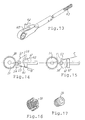
- FIG. 12 is an enlarged elevation view of the opposite side of the part in FIG. 11 .
- FIG. 13 is a front perspective exploded view of parts in FIG. 7 .
- FIGS. 14 and 15 are front elevation views of parts in FIG. 7 .
- FIGS. 16 and 17 are perspective views of parts in FIG. 7 .
- FIGS. 1 thru 5 show the wrench of this invention in both its aligned and pivoted positions. That is, the aligned position is shown in FIGS. 1-4 , and that is when the shown wrench is ready for rotating an unshown workpiece such as a nut, bolt, or screw in the usual clockwise direction for tightening. When a quantifiably torque is applied by this wrench, then it pivots to the FIG. 5 position to indicate the application of that maximum torque, and the user can then stop rotating the wrench.
- This shown instrument is particularly useful in the medical field for rotating threaded fasteners in a patient's body.
- the angular degrees of pivot in FIG. 5 is shown to be thirty degrees. So there is a handle 10 and a jaw 11 pivoted together about a pivot pin 12 extending through the two. A pivot stop 13 on the jaw abuts the handle 10 in both directions of handle pivot, as shown in FIGS. 4 and 5 , to limit the pivotal relationship of the handle relative to the jaw. Surfaces 14 and 16 on the handle abut the stop 13 on the two different sides thereof for the stopped positions, as shown.
- the unshown workpiece would be engaged by the wrench at the ratchet 17 which can be either a one-way or a two-way ratchet, and a two-way is shown.
- the ratchet 17 is shown with a hexagonally shaped hollow for receiving the unshown workpiece for rotating same.
- the wrench extends along a longitudinal axis A in the aligned mode shown in FIG. 4 .
- the handle 10 pivots to the FIG. 5 mode, so no additional torque should be applied.
- the pivot connection between the handle 10 and the jaw 11 is that pivot pin 12 .
- an annular cam 18 with twelve radially extending lobes 19 .
- the cam has thirty-degree intervals of lobes and twelve intervening depressions 21 , as seen in FIG. 12 . That provides for an efficient thirty-degree action explained later and as shown with the angulated handle 10 in FIG. 5 . Thirty degrees is a clearly detectable amount for torque limit application, and yet it is not too much when considering the surgical space limitations.
- the lobes 19 have rounded tips 21 and concave valleys 22 therebetween.
- FIG. 7 shows that the handle 10 is hollow at 23 and slidably receives a cylindrical plunger 24 movable along the axis A.
- a cross pin or cam follower 26 is carried by the plunger 24 and is sequentially engageable in the cam valleys 22 to temporarily hold the cam in a rotated position.
- a ratchet 27 is also mounted on the pin 12 and is rotatable thereabout.
- FIGS. 10 and 11 show that the cam 18 and the ratchet 27 are rotationally connected by a hexagonal interconnection with the cam portion 28 being disposed inside the ratchet opening 29 , thus the two always rotate in unison.
- a compression spring 31 yieldingly forces on the plunger at the plunger collar 32 to urge the follower 26 into snug connect with the cam 18 , as shown in FIG. 7 .
- the ratchet 27 and thus the cam 18 , is held against clockwise rotation by a pawl 32 , as seen in FIG. 8 .
- So teeth 33 on the ratchet 27 and teeth 34 on the pawl 32 interlock to resist clockwise rotation of the assembled ratchet and cam. That holds the handle in the aligned mode along the axis A for clockwise tightening of the workpiece, but only to the limit of urging by the spring 31 on the follower 26 .
- the limit torque can be adjusted by adjusting the compression spring 31 via the slidable sleeve 37 axially positioned by the split threaded cylindrical adjuster 38 and lock plug 39 inside the cylinder 38 for holding the cylinder 38 in axial abutment against the sleeve 37 by means of the lock plug expanding the cylinder 38 into threaded contact with the threaded interior of the hollow handle and its threads at 41 .
- a cap 42 covers the handle end and it can be removed for access to the adjuster 38 for adjusting the force the spring 31 can apply to the follower 26 and thus adjust the torque limit.
- the plunger collar 32 abuts a sleeve 43 threaded into the grip 45 to hold the plunger 24 in leftward axial position and have the spring 31 effective on the plunger in the leftward direction as seen in FIG. 7 , and urging leftward against the plunger, and thus follower 26 .
- cam 18 and ratchet 27 are free to rotate counterclockwise, as seen in FIG. 8 , when the handle is pivoted back to its aligned mode of FIG. 4 .
- the engaged lock 26 which is in that lower valley 22 engages the cam 18 for that counter rotation when the handle pivots into alignment.
- the ratchet 27 and pawl 32 are thus only one-way effective in resisting rotation, and they permit the easy rotational return of the cam and the ratchet 27 while the lock 26 in the cam valley 22 engages the cam for that return rotation.
- the workpiece-engaging end of the wrench can have either a one-way or a two-way ratchet.
- the drawings show a two-way, and FIG. 7 shows the wrench entire assembly with the ratchet 51 rotatable mounted in the jaw pocket 52 which encloses the ratchet 51 for more than a half-circle for rotational containment thereof.
- FIGS. 14 and 15 show the two sets of pawl teeth which respectively engage the ratchet teeth 58 for respective driving rotation of the ratchet in rotating the unshown workpiece.
- the pawl has a lever 59 extending through an opening 60 in the jaw and to the outside of the jaw, as in FIG. 7 , for the wrench user to select and pivot the pawl for the desired engagement.
- the pawl also has a projection 61 disposed on a plane intermediate the two sets of teeth 56 and 57 and through the pawl pivot 54 .
- the projection 61 is located offset from the axis A and is on a line B extending through the center of the ratchet and through the tooth engagement location, as shown in FIG. 14 .
- FIG. 15 shows the same line relationship with a line designated C.
- a pusher 62 is axially movably mounted on the jaw and is spring-urged by a compression spring 63 toward the pawl.
- a compression spring 63 There is a cylindrical opening 64 in the jaw 11 for slidable reception of a plunger 66 on the jaw, and the pusher 62 is contained by the plunger 66 to be urged toward the pawl 53 .
- the pusher 62 has a flat planar face 67 in sliding contact with the projection 61 such that the projection can slide along the face 67 between the pawl positions of FIGS. 14 and 15 .
- the pusher has its projection contact points on the respective lines B and C.
- the pawl 53 is directly and fully forced onto the ratchet with optimum angulation of application of that force.
- There is actually a leverage applied to the pawl with, for instance in FIG. 14 the pusher being applied to the projection such that the pawl is actually being leveraged in a clockwise rotated urging for maximum tooth engagement, considering the axis of pawl pivot on pin 54 and the location of the teeth 56 and projection engagements.
Landscapes
- Engineering & Computer Science (AREA)
- Mechanical Engineering (AREA)
- Details Of Spanners, Wrenches, And Screw Drivers And Accessories (AREA)
Abstract
Description
Claims (18)
Priority Applications (1)
| Application Number | Priority Date | Filing Date | Title |
|---|---|---|---|
| US11/983,996 US7806027B1 (en) | 2007-11-14 | 2007-11-14 | Torque limiter wrench and method |
Applications Claiming Priority (1)
| Application Number | Priority Date | Filing Date | Title |
|---|---|---|---|
| US11/983,996 US7806027B1 (en) | 2007-11-14 | 2007-11-14 | Torque limiter wrench and method |
Publications (1)
| Publication Number | Publication Date |
|---|---|
| US7806027B1 true US7806027B1 (en) | 2010-10-05 |
Family
ID=42797634
Family Applications (1)
| Application Number | Title | Priority Date | Filing Date |
|---|---|---|---|
| US11/983,996 Expired - Fee Related US7806027B1 (en) | 2007-11-14 | 2007-11-14 | Torque limiter wrench and method |
Country Status (1)
| Country | Link |
|---|---|
| US (1) | US7806027B1 (en) |
Cited By (13)
| Publication number | Priority date | Publication date | Assignee | Title |
|---|---|---|---|---|
| USD652138S1 (en) | 2011-02-12 | 2012-01-10 | Eca Medical Instruments | Divoted medical instrument handle |
| USD652137S1 (en) | 2011-02-12 | 2012-01-10 | Eca Medical Instruments | Bulb shape medical instrument handle |
| USD655413S1 (en) | 2011-02-12 | 2012-03-06 | Eca Medical Instruments | Undulated medical instrument handle |
| US20120297932A1 (en) * | 2011-05-26 | 2012-11-29 | Torqbuddy Llc | Two Handed Portable Power Wrench |
| US9162350B2 (en) | 2010-07-28 | 2015-10-20 | Eca Medical Instruments | Robust nose torque-limiting device |
| US20160207181A1 (en) * | 2015-01-20 | 2016-07-21 | The Boeing Company | Torque-wrench apparatuses and methods of assembling the same |
| US9664315B1 (en) * | 2014-08-20 | 2017-05-30 | Samsung Electronics Co., Ltd. | One-way nut fastener |
| US9694481B2 (en) | 2014-09-16 | 2017-07-04 | Fit-Line, Inc. | Torque limiting wrench for plastic and other fittings |
| TWI632993B (en) * | 2017-11-24 | 2018-08-21 | 優鋼機械股份有限公司 | Folding arm torque wrench capable of quickly adjusting torque |
| US10279146B2 (en) | 2015-06-02 | 2019-05-07 | Eca Medical Instruments | Cannulated disposable torque limiting device with plastic shaft |
| CN113842198A (en) * | 2021-09-08 | 2021-12-28 | 汕头大学 | A 3D printed rotary locking cervical spine reducer |
| US11396091B2 (en) | 2020-04-03 | 2022-07-26 | Milwaukee Electric Tool Corporation | Torque wrench |
| US20220288763A1 (en) * | 2021-03-09 | 2022-09-15 | Snap-On Incorporated | Multi-piece housing for indexable motorized ratchet tools |
Citations (6)
| Publication number | Priority date | Publication date | Assignee | Title |
|---|---|---|---|---|
| US3893354A (en) * | 1974-09-30 | 1975-07-08 | Jo Line Tools | Torque limit wrench |
| US4019412A (en) * | 1975-09-12 | 1977-04-26 | Kraus Robert A | Torque release wrench |
| US5337638A (en) * | 1993-02-11 | 1994-08-16 | Micro Motors, Inc. | Torque control ratchet wrench |
| US5557994A (en) * | 1995-07-17 | 1996-09-24 | Nakayama; Tatsuo | Ratchet handle with torque adjustment |
| US6742418B2 (en) * | 2001-10-29 | 2004-06-01 | Kuken Co., Ltd. | Torque wrench |
| US20070039432A1 (en) * | 2005-08-18 | 2007-02-22 | Cutler Brian J | Torque-Indicating Driver and Method |
-
2007
- 2007-11-14 US US11/983,996 patent/US7806027B1/en not_active Expired - Fee Related
Patent Citations (6)
| Publication number | Priority date | Publication date | Assignee | Title |
|---|---|---|---|---|
| US3893354A (en) * | 1974-09-30 | 1975-07-08 | Jo Line Tools | Torque limit wrench |
| US4019412A (en) * | 1975-09-12 | 1977-04-26 | Kraus Robert A | Torque release wrench |
| US5337638A (en) * | 1993-02-11 | 1994-08-16 | Micro Motors, Inc. | Torque control ratchet wrench |
| US5557994A (en) * | 1995-07-17 | 1996-09-24 | Nakayama; Tatsuo | Ratchet handle with torque adjustment |
| US6742418B2 (en) * | 2001-10-29 | 2004-06-01 | Kuken Co., Ltd. | Torque wrench |
| US20070039432A1 (en) * | 2005-08-18 | 2007-02-22 | Cutler Brian J | Torque-Indicating Driver and Method |
Cited By (19)
| Publication number | Priority date | Publication date | Assignee | Title |
|---|---|---|---|---|
| US9162350B2 (en) | 2010-07-28 | 2015-10-20 | Eca Medical Instruments | Robust nose torque-limiting device |
| US10219853B2 (en) | 2010-07-28 | 2019-03-05 | Eca Medical Instruments | Robust nose torque-limiting device |
| USD652138S1 (en) | 2011-02-12 | 2012-01-10 | Eca Medical Instruments | Divoted medical instrument handle |
| USD652137S1 (en) | 2011-02-12 | 2012-01-10 | Eca Medical Instruments | Bulb shape medical instrument handle |
| USD655413S1 (en) | 2011-02-12 | 2012-03-06 | Eca Medical Instruments | Undulated medical instrument handle |
| US20120297932A1 (en) * | 2011-05-26 | 2012-11-29 | Torqbuddy Llc | Two Handed Portable Power Wrench |
| US8677862B2 (en) * | 2011-05-26 | 2014-03-25 | Torqbuddy Llc | Two handed portable power wrench |
| US9664315B1 (en) * | 2014-08-20 | 2017-05-30 | Samsung Electronics Co., Ltd. | One-way nut fastener |
| US9694481B2 (en) | 2014-09-16 | 2017-07-04 | Fit-Line, Inc. | Torque limiting wrench for plastic and other fittings |
| US9855643B2 (en) * | 2015-01-20 | 2018-01-02 | The Boeing Company | Torque-wrench apparatuses and methods of assembling the same |
| US20160207181A1 (en) * | 2015-01-20 | 2016-07-21 | The Boeing Company | Torque-wrench apparatuses and methods of assembling the same |
| US10279146B2 (en) | 2015-06-02 | 2019-05-07 | Eca Medical Instruments | Cannulated disposable torque limiting device with plastic shaft |
| TWI632993B (en) * | 2017-11-24 | 2018-08-21 | 優鋼機械股份有限公司 | Folding arm torque wrench capable of quickly adjusting torque |
| US11396091B2 (en) | 2020-04-03 | 2022-07-26 | Milwaukee Electric Tool Corporation | Torque wrench |
| US11833645B2 (en) | 2020-04-03 | 2023-12-05 | Milwaukee Electric Tool Corporation | Torque wrench |
| US12257673B2 (en) | 2020-04-03 | 2025-03-25 | Milwaukee Electric Tool Corporation | Torque wrench |
| US20220288763A1 (en) * | 2021-03-09 | 2022-09-15 | Snap-On Incorporated | Multi-piece housing for indexable motorized ratchet tools |
| CN113842198A (en) * | 2021-09-08 | 2021-12-28 | 汕头大学 | A 3D printed rotary locking cervical spine reducer |
| CN113842198B (en) * | 2021-09-08 | 2024-02-20 | 汕头大学 | Rotary locking type cervical vertebra restorer with 3D printing function |
Similar Documents
| Publication | Publication Date | Title |
|---|---|---|
| US7806027B1 (en) | Torque limiter wrench and method | |
| US11850707B2 (en) | Locking pliers with movable torque-increasing jaw section | |
| US7878091B2 (en) | Screwdriving tool with free wheel gear | |
| US6976410B2 (en) | Tool bit drive adaptor | |
| US8919227B2 (en) | Pliers for C-shaped lock rings | |
| US20170151656A1 (en) | Universal ratcheting tool | |
| AU2008201152A1 (en) | Wrench | |
| US7117771B2 (en) | Self-adjusting, locking pliers with gripping force adjustment | |
| US20080178710A1 (en) | Adjustable pivotal wrench | |
| EP2844432B1 (en) | Open-ended ratchet wrench | |
| JP2012505501A (en) | Crimping tool | |
| US7290465B2 (en) | Ratchet driver and method of making same | |
| TWI461262B (en) | Wrench with trigger | |
| US7143670B2 (en) | Compact auxiliary positioning driver for wrench | |
| WO2010002239A1 (en) | Improvement to adjustable ratchet wrench or spanner | |
| US7997168B2 (en) | Adjustable ratchet wrench | |
| US20140144294A1 (en) | Adjustable Open End Ratcheting Flare Wrench | |
| CA2806944C (en) | Open-ended ratchet wrench | |
| GB2411613A (en) | Pipe wrench with pivoting jaws | |
| US12036639B2 (en) | Adjustable fastener engaging tool | |
| US20090031866A1 (en) | Cam Compression Tool | |
| US20050109168A1 (en) | Self-tightening adjustable wrench | |
| CA2599722C (en) | Adjustable ratchet wrench | |
| TW202012110A (en) | Locking pliers with movable torque-increasing jaw section | |
| US8302511B1 (en) | Leverage tool |
Legal Events
| Date | Code | Title | Description |
|---|---|---|---|
| AS | Assignment |
Owner name: BRADSHAW MEDICAL, INC, WISCONSIN Free format text: ASSIGNMENT OF ASSIGNORS INTEREST;ASSIGNOR:GAO, HUA;REEL/FRAME:020159/0871 Effective date: 20071105 |
|
| STCF | Information on status: patent grant |
Free format text: PATENTED CASE |
|
| REMI | Maintenance fee reminder mailed | ||
| FPAY | Fee payment |
Year of fee payment: 4 |
|
| SULP | Surcharge for late payment | ||
| MAFP | Maintenance fee payment |
Free format text: PAYMENT OF MAINTENANCE FEE, 8TH YR, SMALL ENTITY (ORIGINAL EVENT CODE: M2552) Year of fee payment: 8 |
|
| FEPP | Fee payment procedure |
Free format text: MAINTENANCE FEE REMINDER MAILED (ORIGINAL EVENT CODE: REM.); ENTITY STATUS OF PATENT OWNER: SMALL ENTITY |
|
| LAPS | Lapse for failure to pay maintenance fees |
Free format text: PATENT EXPIRED FOR FAILURE TO PAY MAINTENANCE FEES (ORIGINAL EVENT CODE: EXP.); ENTITY STATUS OF PATENT OWNER: SMALL ENTITY |
|
| STCH | Information on status: patent discontinuation |
Free format text: PATENT EXPIRED DUE TO NONPAYMENT OF MAINTENANCE FEES UNDER 37 CFR 1.362 |
|
| FP | Lapsed due to failure to pay maintenance fee |
Effective date: 20221005 |