US7805876B1 - Laser gunsight system for a firearm handgrip - Google Patents
Laser gunsight system for a firearm handgrip Download PDFInfo
- Publication number
- US7805876B1 US7805876B1 US12/152,260 US15226008A US7805876B1 US 7805876 B1 US7805876 B1 US 7805876B1 US 15226008 A US15226008 A US 15226008A US 7805876 B1 US7805876 B1 US 7805876B1
- Authority
- US
- United States
- Prior art keywords
- firearm
- sleeve
- sighting device
- handgrip
- protrusion
- Prior art date
- Legal status (The legal status is an assumption and is not a legal conclusion. Google has not performed a legal analysis and makes no representation as to the accuracy of the status listed.)
- Active, expires
Links
- 229920001169 thermoplastic Polymers 0.000 claims description 2
- 239000004416 thermosoftening plastic Substances 0.000 claims description 2
- 230000004913 activation Effects 0.000 claims 2
- 230000000717 retained effect Effects 0.000 claims 2
- 210000003811 finger Anatomy 0.000 description 12
- 238000010304 firing Methods 0.000 description 9
- 238000009434 installation Methods 0.000 description 7
- 239000000463 material Substances 0.000 description 4
- 230000000694 effects Effects 0.000 description 3
- 210000004932 little finger Anatomy 0.000 description 3
- 239000004033 plastic Substances 0.000 description 3
- 239000004677 Nylon Substances 0.000 description 2
- 241000321728 Tritogonia verrucosa Species 0.000 description 2
- 210000004247 hand Anatomy 0.000 description 2
- 230000004048 modification Effects 0.000 description 2
- 238000012986 modification Methods 0.000 description 2
- 229920001778 nylon Polymers 0.000 description 2
- 210000003813 thumb Anatomy 0.000 description 2
- 241000237503 Pectinidae Species 0.000 description 1
- NWGKJDSIEKMTRX-AAZCQSIUSA-N Sorbitan monooleate Chemical compound CCCCCCCC\C=C/CCCCCCCC(=O)OC[C@@H](O)[C@H]1OC[C@H](O)[C@H]1O NWGKJDSIEKMTRX-AAZCQSIUSA-N 0.000 description 1
- YZCKVEUIGOORGS-NJFSPNSNSA-N Tritium Chemical compound [3H] YZCKVEUIGOORGS-NJFSPNSNSA-N 0.000 description 1
- 238000005452 bending Methods 0.000 description 1
- 210000000078 claw Anatomy 0.000 description 1
- 230000001010 compromised effect Effects 0.000 description 1
- 210000005224 forefinger Anatomy 0.000 description 1
- 230000003760 hair shine Effects 0.000 description 1
- 238000005286 illumination Methods 0.000 description 1
- 230000013011 mating Effects 0.000 description 1
- 239000002991 molded plastic Substances 0.000 description 1
- 238000000465 moulding Methods 0.000 description 1
- 230000003287 optical effect Effects 0.000 description 1
- 230000000284 resting effect Effects 0.000 description 1
- 239000005060 rubber Substances 0.000 description 1
- 235000020637 scallop Nutrition 0.000 description 1
- 230000035807 sensation Effects 0.000 description 1
- 229910052722 tritium Inorganic materials 0.000 description 1
Images


Classifications
-
- F—MECHANICAL ENGINEERING; LIGHTING; HEATING; WEAPONS; BLASTING
- F41—WEAPONS
- F41G—WEAPON SIGHTS; AIMING
- F41G1/00—Sighting devices
- F41G1/32—Night sights, e.g. luminescent
- F41G1/34—Night sights, e.g. luminescent combined with light source, e.g. spot light
- F41G1/35—Night sights, e.g. luminescent combined with light source, e.g. spot light for illuminating the target, e.g. flash lights
-
- F—MECHANICAL ENGINEERING; LIGHTING; HEATING; WEAPONS; BLASTING
- F41—WEAPONS
- F41C—SMALLARMS, e.g. PISTOLS, RIFLES; ACCESSORIES THEREFOR
- F41C23/00—Butts; Butt plates; Stocks
- F41C23/10—Stocks or grips for pistols, e.g. revolvers
-
- F—MECHANICAL ENGINEERING; LIGHTING; HEATING; WEAPONS; BLASTING
- F41—WEAPONS
- F41G—WEAPON SIGHTS; AIMING
- F41G11/00—Details of sighting or aiming apparatus; Accessories
- F41G11/001—Means for mounting tubular or beam shaped sighting or aiming devices on firearms
-
- F—MECHANICAL ENGINEERING; LIGHTING; HEATING; WEAPONS; BLASTING
- F41—WEAPONS
- F41G—WEAPON SIGHTS; AIMING
- F41G11/00—Details of sighting or aiming apparatus; Accessories
- F41G11/001—Means for mounting tubular or beam shaped sighting or aiming devices on firearms
- F41G11/004—Mountings with clamping means on the device embracing at least a part of the firearm, e.g. the receiver or a dustcover
Definitions
- This invention relates to a laser gunsight system designed to fit the handgrip of a firearm without requiring significant modification of the firearm, the laser gunsight being operable by the user while the firearm is gripped by the handgrip in the firing position.
- sights have been developed wherein a battery-powered laser is used, the laser having been adjusted to illuminate the point of aim of the firearm.
- the laser When the laser is turned on by the user of the firearm, it shines light in the direction the bullet will travel when the firearm is fired.
- the firearm is aimed merely by directing the laser beam towards the target. The laser beam strikes the target and is reflected back to the user's eye, informing the user exactly where the firearm is aimed and thus what the point of impact of a bullet will be if the firearm is fired.
- Various laser gunsight systems have been developed for use with firearms that are equipped with a handgrip, such as handguns, or long guns having a buttstock with a “pistol-grip”.
- the handgrip of a handgun is grasped by the user's hand or hands when the firearm is being held in the firing position.
- a long gun i.e., a rifle or a shotgun
- typically the rear or “trigger” hand holds the handgrip while the front hand holds the forestock when the firearm is in the firing position.
- Kaminski U.S. Pat. Nos. 5,704,153 and 5,867,930, discloses a firearm battery and control module for a gunsight laser wherein the battery and control circuitry are contained within a housing that fits inside the handgrip of a firearm.
- the stock handgrip that is, the handgrip that the firearm is normally provided with by the manufacturer, must be replaced with a specially adapted or custom handgrip containing components of the laser gunsight system to allow this system to be used.
- U.S. Pat. No. 6,591,536 discloses a laser assembly that is mounted on the side of a handgun frame above the trigger, the switch being contained in the unit and typically operated by the user's trigger finger.
- Teetzel U.S. Pat. No. 5,481,819, discloses a laser sight that may be used on a handgun, the switch and circuitry for which is located inside modified custom handgrips that replace the stock handgrips supplied with the firearm.
- Toole et al. U.S. Pat. No. 5,706,600 discloses a laser sight that may be used on a handgun wherein the laser is disposed forward of the trigger guard, a switch is disposed below the trigger guard and a power supply is disposed within the handgrip of the firearm.
- Toole, et al., U.S. Pat. No. 5,435,091 discloses a laser sight disposed at the top of the handgrip rearward of the trigger wherein the power supply and circuitry is contained within a customized handgrip.
- Danielson, U.S. Pat. No. 7,260,910 discloses a pistol handgrip mounted laser device that is designed for use on pistols without removable handgrips, such as plastic framed pistols.
- the disclosed device wraps about the sides and rear of the pistol, and has an actuation switch at the rear, where it is activated by pressure from the web of the user's hand. For some users, alternative switch locations may be preferred.
- the body of the device adds thickness at the upper rear of the grip, making it less suitable for users with other comfort and feel preferences, as it shifts the hand back slightly with respect to the trigger, and increases the effective circumference of the pistol grip.
- the disclosed grip is secured against removal by sharing a pin that extends laterally through the frame of the pistol, at rear of the grip toward the upper end.
- Many pistols lack this attachment point, and thus cannot use the disclosed device. Even for those pistols with such an attachment point, the minor pistol disassembly required for installation may cause some users to be reluctant to attempt installation, and may limit the market for the product.
- the present invention overcomes the limitations of the prior art by providing a sighting device for a firearm having a handgrip with a front strap, a back strap, and a free end.
- the sighting device has a body including a sleeve defining a bore sized to closely encircle at least a portion of the handgrip.
- the sleeve has a front portion configured to wrap about at least a forward front strap portion of the firearm, and has a rear portion configured to wrap about at least a rear back strap portion of the firearm.
- a laser device is connected to the body.
- the body may be an integral element, and may have a switch on the front span.
- the body may have a removable lock device that engages an upper rear protrusion of the frame, and the device may attach to the firearm without any fasteners engaging the firearm.
- FIG. 1 is a right side view of a preferred embodiment of the invention as installed on a pistol.
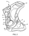
- FIG. 2 is a perspective view of the embodiment of FIG. 1 , showing the interior of the device.
- FIG. 3 is an exploded perspective view of the embodiment of FIG. 1 showing a locking piece removed.
- FIG. 4 is a medial sectional view of the preferred embodiment, taken along line 4 - 4 of FIG. 3 .
- FIG. 5 is an axial sectional view of the preferred embodiment, taken along line 5 - 5 of FIG. 1 .
- FIG. 1 shows a firearm 10 with an attached laser aiming device 12 .
- the pistol has a one-piece integrally molded plastic frame 14 that includes an upper edge 16 immediately below the lower edge of a slide 20 that reciprocates with respect to the pistol during chambering of cartridges and ejection of casings.
- the device may be employed on any type of pistol or firearm in addition to those with integrally-molded frames.
- the frame has a downwardly-extending handgrip 22 that angles slightly rearward and is a tubular body defining a well receiving a magazine 24 .
- the handgrip has a lower free end 26 .
- the grip has flat side portions 30 , and a curved front strap 32 facing forward, and a curved back strap 34 facing to the rear.
- the grip generally has an oblong or “racetrack” cross section.
- a trigger guard 36 projects forward, and protects the trigger 40 .
- the back strap extends nearly to the upper edge 16 of the frame, curving rearward at its upper portion.
- a beavertail protrusion portion 42 of the frame protrudes rearward at the upper end of the back strap.
- the beavertail has an angled upper surface 44 that is below the plane of the upper edge 46 , and faces upward at an angle toward the rear.
- a grip safety switch 50 protrudes slightly. The grip safety is spring biased to the “safe” position shown, so that the gun will not fire even when the trigger is pulled.
- a compact version of the same pistol is shown in dashed lines, with the only difference being that the grip length is reduced, so that the lower end 26 ′ is higher than the end 26 of the full-size pistol, and the magazine 24 ′ does not extend as far as the full size magazine 24 .
- the device When a user grips the gun normally with his hand 52 , the web of flesh 54 between palm and forefinger presses against the back strap and depresses the grip safety, which pivots to an “off” position where firing is enabled.
- the user's index (trigger) finger 56 is within the trigger guard and presses the trigger for firing.
- the middle finger 60 is positioned immediately below the trigger guard, just forward of the front strap.
- the ring finger 62 is positioned just below the middle finger, resting on the front strap.
- the little finger 64 is below the ring finger, just above a protrusion 66 on the front edge of a plate at the lower end of the magazine. In the compact pistol embodiment, the ring finger is just above the magazine plate protrusion 66 ′, and the little finger generally curls underneath the bottom of the magazine.
- FIG. 2 shows the laser aiming device 12 separate from the pistol.
- the device has a left panel 70 , an opposed right panel 72 , a curved front span portion 74 smoothly joining the front edges of the side panels, and a curved lower rear span portion 76 smoothly joining the lower edges of the side panels.
- An upper rear span portion 80 smoothly joins the upper rear corners of the side panels.
- the side panels are somewhat triangularly shaped.
- the panels and spans are smoothly transitioned to each other, and the edges of the panels and spans are complex curves.
- the amorphous or organic shape is partly dictated by the goal that the device have minimal perceived effect on the size of the grip in a user's hands. This means that the device has the minimum volume to enclose needed components, and dimensions needed for strength and durability.
- the illustrated curved shapes are provided for an aesthetic appearance and for comfort.
- the minimal, “skeletonized” form also minimizes weight, and further facilitates installation and removal of the device from the firearm by reducing friction and potential interference.
- the body forms a “sleeve” in the sense that it has one or more topologically continuous loops or bands, with no interruptions as it encompasses or encircles the space in which the handgrip will closely be received.
- a “sleeve” is formed by the ring formed by side panels and front and lower rear spans even if the upper rear span were not connected.
- a sleeve may said to be formed by the side panels, front span and upper rear span even if the lower rear span were not present or connected.
- the device has a body molded as a single piece from thermoplastic such as nylon or ABS, with nylon material used for pistol frames, thereby providing compatibility. While no plastic is entirely rigid, the material is essentially rigid in the sense that it does not elongate or compress in any significant way that affects dimensions or functionality during installation or use. The only flexure of significance is in bending of flat panel portions, to allow certain portions to bend out of the way for installation over protrusions, and to snap into place when properly seated.
- the body is essentially inelastic, and this provides a material comparable in characteristics and appearance to materials used for molding plastic pistol frames.
- the body contains a number of electronic components.
- a flat, disc-shaped battery 82 is contained in a recess in the inner face of each side panel.
- a momentary on-off switch 84 having a flexible rubber actuator is mounted at the center of the front span.
- a laser diode 86 is mounted within the upper front portion at as high a location as possible (but below the level of the lower slide edge) to avoid interference by the user's grip hand with the laser beam, and intrusion of the portion of the body into the area where the hand must comfortably rest.
- Set screws in the body provide aiming adjustments of the laser with respect to the body.
- Control circuitry 88 is mounted in an interior recess, and the components are interconnected by thin flexible circuitry or wires 90 .
- the circuitry also connects to a master power switch 92 that is recessed in the outside of the left side panel, so that the entire device may be disabled when not in use to prevent accidental actuation and preserve battery life.
- FIG. 3 shows the device 12 installed on but not fully secured to the pistol 10 .
- the upper surface 44 of the beavertail is exposed, and the rear span of the device has been slid upwards past the beavertail, because there are no portions to interfere with passage.
- a rear lock piece 94 slides into a recess 96 in the rear of the device body at the upper rear span 80 .
- the lock piece has an overhang ledge surface 100 that abuts the surface 44 when fully installed, and the overhang prevents removal.
- a pin 102 is inserted in lateral bores 104 in the device body, and bore 106 in the lock piece.
- the lateral ends of the lock piece define fore-aft channels that closely mate with rails in the recess, for a tongue-and-groove or dovetail effect that secures the lock piece against rotation.
- FIG. 4 shows the engagement of the pistol's beavertail protrusion 42 and its upper surface 44 with the surface 100 of the locking piece 94 .
- This also illustrates a “triangle of stability” provided by the three spans. Any elongated body may stably be located by gripping at two spaced-apart points on one side, and at an intermediate point on the other side. That is what the preferred embodiment does.
- the side panels and close fit prevent the device from shifting or rotating in most directions and axes.
- the three spans prevent rotation about a lateral axis (perpendicular to medial plane of the pistol.)
- the upper rear span and front span prevent rotation in a forward direction (CCW in FIG. 4 ), and the lower rear and front spans prevent rotation rearward.
- one of the three spans may be eliminated while still providing a secure mount.
- Positive location of the device with respect to the pistol is important, because any changes will result in misalignment of the laser beam from the point of impact of a projectile. Without the lower rear span, the device may still be stably held because the front strap is positively located vertically by the trigger guard, and the locking piece engagement of the beavertail prevents the rearward rotation normally prevented by the lower rear span.
- the secure mounting is provided with no fasteners engaging the pistol.
- nothing on the pistol needs to be modified, adjusted, moved, removed, or reinstalled. This ensures that proper assembly and safety measures are not compromised, and that users will feel comfortable installing their own device, avoid the expense of professional installation.
- the device is kept secure on the frame by a close conformance of the interior of the body to the exterior of the handgrip.
- the frame is provided on its sides with oval recesses or “thumb scallops” 110 (also indicated in FIG. 1 ) that provide a comfortable place for left or right handed users to rest the thumb of the trigger hand.
- the device body interior has corresponding oval bumps 112 that conform to the shape of the recesses.
- the mating feature provides a detectable “detent” that helps the installer to confidently know when the device is fully installed.
- the principle of surface conformance may be employed on any portion or the entire interior of the device, with the shape set to conform to finger grooves found on the front straps of some pistols, or to be molded with a pattern that mates with the checkering, stippling, or any other texture provided on firearm grips.
- the grip in a full size pistol with a double stack magazine of common caliber (e.g. 9 mm, 40 S&W, 45ACP) the grip has a width of 1.0-1.25 inch.
- the grip length is typically about 4 inches in a full-size pistol, and about an inch less for a compact pistol. While these may vary among models and brands, they provide a context for the details of the preferred embodiment.
- about 2.0-2.5 inches of the upper back strap is exposed above the rear span, and the rear edges of the side panels are about 0.5 inch forward of the rear point of the back strap. This provides the comfortable feeling of a grip that is not perceived as significantly enlarged.
- the rear span 76 has a width of less than 0.5 inch, and a thickness of only about 0.062 inch.
- the front span has a width of about 7 ⁇ 8 inch, which is sized to reflect the width of an adult middle finger that will rest here as shown in FIG. 1 .
- the front span has a concave form that wraps about the front to provide a finger groove to naturally seat the illumination control finger over the switch. With its limited width, the next (ring) finger comfortably abuts the lower part of the front span, and grips the pistol's front strap, as does the little finger. This provides the sensation of a natural grip size, because only one (middle) finger is wrapping about an enlarged portion of the grip.
- the side panels are contoured to be thick at their middles, and thin at their edges. This provides a desirably comfortable “palm swell” that does not significantly increase perceived circumference (adding a slight curve to a flat panel having minimal effect on the circumference.)
- one side panel may be omitted, and the device still secured by the front span, two (or even one) back spans, and one side panel joining them.
- Such a device would appear as a three-toed (or even two-toed) penannular “claw”, and if sufficiently rigid, would provide adequate stability.
- Other embodiment may employ some elastomeric components that stretch to install over bulges, and provide adequate tension to retain the device in position.
- the device may similarly be applied to a rifle having a protruding handgrip, or to a firearm handgrip in a forward location such as mounted in front of the magazine of a military rifle for gripping with the non-trigger hand.
Landscapes
- Engineering & Computer Science (AREA)
- General Engineering & Computer Science (AREA)
- Physics & Mathematics (AREA)
- Optics & Photonics (AREA)
- Aiming, Guidance, Guns With A Light Source, Armor, Camouflage, And Targets (AREA)
Abstract
Description
Claims (21)
Priority Applications (1)
| Application Number | Priority Date | Filing Date | Title |
|---|---|---|---|
| US12/152,260 US7805876B1 (en) | 2008-05-12 | 2008-05-12 | Laser gunsight system for a firearm handgrip |
Applications Claiming Priority (1)
| Application Number | Priority Date | Filing Date | Title |
|---|---|---|---|
| US12/152,260 US7805876B1 (en) | 2008-05-12 | 2008-05-12 | Laser gunsight system for a firearm handgrip |
Publications (1)
| Publication Number | Publication Date |
|---|---|
| US7805876B1 true US7805876B1 (en) | 2010-10-05 |
Family
ID=42797625
Family Applications (1)
| Application Number | Title | Priority Date | Filing Date |
|---|---|---|---|
| US12/152,260 Active 2029-03-27 US7805876B1 (en) | 2008-05-12 | 2008-05-12 | Laser gunsight system for a firearm handgrip |
Country Status (1)
| Country | Link |
|---|---|
| US (1) | US7805876B1 (en) |
Cited By (71)
| Publication number | Priority date | Publication date | Assignee | Title |
|---|---|---|---|---|
| US20100154279A1 (en) * | 2008-12-23 | 2010-06-24 | Para Usa, Inc. | Firearm |
| US20110138667A1 (en) * | 2009-12-14 | 2011-06-16 | Bolden Eric L | Handgun identification light |
| US20120047787A1 (en) * | 2010-08-30 | 2012-03-01 | Smith & Wesson Corp. | Frame-mounted laser aiming device |
| US20120159832A1 (en) * | 2008-09-05 | 2012-06-28 | Moore Larry E | Gun with mounted sighting device |
| USD669553S1 (en) | 2011-05-11 | 2012-10-23 | Crimson Trace, Inc. | Laser device |
| USD669552S1 (en) | 2011-06-29 | 2012-10-23 | Crimson Trace, Inc. | Laser device |
| USD669959S1 (en) | 2011-06-29 | 2012-10-30 | Crimson Trace, Inc. | Illumination device |
| USD669958S1 (en) | 2011-05-10 | 2012-10-30 | Crimson Trace, Inc. | Laser device |
| USD669957S1 (en) | 2011-05-10 | 2012-10-30 | Crimson Trace, Inc. | Laser device |
| USD674861S1 (en) | 2011-06-29 | 2013-01-22 | Crimson Trace, Inc. | Illumination device |
| USD674862S1 (en) | 2011-06-29 | 2013-01-22 | Crimson Trace, Inc. | Illumination device |
| USD676097S1 (en) | 2011-12-19 | 2013-02-12 | Battle Tek Industries Incorporated | Grip light |
| USD687120S1 (en) | 2011-11-09 | 2013-07-30 | Crimson Trace, Inc. | Laser device |
| USD689162S1 (en) | 2012-02-21 | 2013-09-03 | Crimson Trace, Inc. | Dual laser device |
| USD692518S1 (en) | 2011-11-09 | 2013-10-29 | Crimson Trace, Inc. | Laser device |
| USD693898S1 (en) | 2011-11-02 | 2013-11-19 | Crimson Trace, Inc. | Laser device |
| USD694848S1 (en) | 2011-11-09 | 2013-12-03 | Crimson Trace, Inc. | Laser |
| USD694847S1 (en) | 2011-11-09 | 2013-12-03 | Crimson Trace, Inc. | Laser device |
| US8607495B2 (en) | 2008-10-10 | 2013-12-17 | Larry E. Moore | Light-assisted sighting devices |
| USD696376S1 (en) | 2011-06-29 | 2013-12-24 | Crimson Trace, Inc. | Laser device |
| US8627591B2 (en) | 2008-09-05 | 2014-01-14 | Larry Moore | Slot-mounted sighting device |
| US8662694B1 (en) | 2012-01-11 | 2014-03-04 | Battle Tek Industries Incorporated | Illumination device and method |
| US8695266B2 (en) | 2005-12-22 | 2014-04-15 | Larry Moore | Reference beam generating apparatus |
| US8696150B2 (en) | 2011-01-18 | 2014-04-15 | Larry E. Moore | Low-profile side mounted laser sighting device |
| US8813411B2 (en) | 2008-10-10 | 2014-08-26 | P&L Industries, Inc. | Gun with side mounting plate |
| US8844189B2 (en) | 2012-12-06 | 2014-09-30 | P&L Industries, Inc. | Sighting device replicating shotgun pattern spread |
| US8915009B2 (en) | 2010-11-16 | 2014-12-23 | Crimson Trace Corporation | Modular sighting and lighting system for handguns |
| RU2539019C1 (en) * | 2013-09-23 | 2015-01-10 | Александр Юрьевич Яшин | Gun with laser target designator |
| USD738987S1 (en) * | 2014-04-23 | 2015-09-15 | Crimson Trace Corporation | Laser device |
| US9170079B2 (en) | 2011-01-18 | 2015-10-27 | Larry E. Moore | Laser trainer cartridge |
| US9182194B2 (en) | 2014-02-17 | 2015-11-10 | Larry E. Moore | Front-grip lighting device |
| US9243865B1 (en) * | 2015-01-03 | 2016-01-26 | Hogue, Inc. | Firearm handgrip assembly with laser gunsight system |
| US9297614B2 (en) | 2013-08-13 | 2016-03-29 | Larry E. Moore | Master module light source, retainer and kits |
| USD755341S1 (en) * | 2014-10-14 | 2016-05-03 | Crimson Trace Corporation | Laser device |
| USD757206S1 (en) * | 2014-04-28 | 2016-05-24 | Rade Tecnologias, S.L. | Target-illuminating aiming device |
| US9453702B2 (en) * | 2015-01-09 | 2016-09-27 | Hogue, Inc. | Firearm handgrip assembly with laser gunsight system |
| EP2685202A3 (en) * | 2012-07-09 | 2017-03-08 | Value Privatstiftung | Gripp for a firearm |
| US20170082399A1 (en) * | 2015-09-23 | 2017-03-23 | Larry E. Moore | Grip aiming device for weapons |
| US9644826B2 (en) | 2014-04-25 | 2017-05-09 | Larry E. Moore | Weapon with redirected lighting beam |
| US20170146315A1 (en) * | 2015-01-09 | 2017-05-25 | Hogue, Inc. | Firearm handgrip assembly with laser gunsight system |
| US9752849B2 (en) * | 2015-05-26 | 2017-09-05 | Crimson Trace Corporation | Recoil-inhibiting grips for firearms |
| US9777983B2 (en) | 2013-11-13 | 2017-10-03 | Recover, Llc | Integrated handgun grip and rail |
| US9829280B1 (en) | 2016-05-26 | 2017-11-28 | Larry E. Moore | Laser activated moving target |
| USD812181S1 (en) * | 2016-07-28 | 2018-03-06 | Crimson Trace Corporation | Laser device |
| US9909830B1 (en) | 2017-01-23 | 2018-03-06 | Lumen Defense Products Inc | Modular firearm grip cover assembly with sighting device |
| US9921027B2 (en) | 2015-12-29 | 2018-03-20 | Hogue, Inc. | Firearm handgrip assembly with laser gunsight system |
| USD825707S1 (en) * | 2016-07-29 | 2018-08-14 | Crimson Trace Corporation | Laser device |
| USD830490S1 (en) | 2017-01-23 | 2018-10-09 | Lumen Defense Products Inc | Grip cover with laser sight |
| US10132595B2 (en) | 2015-03-20 | 2018-11-20 | Larry E. Moore | Cross-bow alignment sighter |
| US20180347944A1 (en) * | 2013-11-18 | 2018-12-06 | Richard George Hovsepian | Flush Switch for Handgun Accessory |
| US10197359B1 (en) * | 2017-07-15 | 2019-02-05 | Lumen Defense Products Inc | Grip-mounted laser sight for a handgun |
| USD840491S1 (en) | 2017-02-10 | 2019-02-12 | AIM Sports Inc. | Featureless backstrap for a grip for firearms |
| USD840492S1 (en) | 2017-02-10 | 2019-02-12 | AIM Sports Inc. | Featureless backstrap for a grip for firearms |
| US10209033B1 (en) | 2018-01-30 | 2019-02-19 | Larry E. Moore | Light sighting and training device |
| US10209030B2 (en) | 2016-08-31 | 2019-02-19 | Larry E. Moore | Gun grip |
| US20190186867A1 (en) * | 2015-01-09 | 2019-06-20 | Hogue, Inc. | Firearm handgrip assembly with laser gunsight system |
| US10365069B1 (en) | 2018-03-30 | 2019-07-30 | Battenfeld Technologies, Inc. | Firearm accessory having firearm mount |
| CN110185906A (en) * | 2019-06-28 | 2019-08-30 | 北京圣奥安防科技有限公司 | Tamper locking device |
| US10436553B2 (en) | 2014-08-13 | 2019-10-08 | Crimson Trace Corporation | Master module light source and trainer |
| US10436538B2 (en) | 2017-05-19 | 2019-10-08 | Crimson Trace Corporation | Automatic pistol slide with laser |
| US10532275B2 (en) | 2012-01-18 | 2020-01-14 | Crimson Trace Corporation | Laser activated moving target |
| US10578395B2 (en) * | 2016-09-01 | 2020-03-03 | Crosman Corporation | Grip activation system for firearm accessory |
| US11105586B2 (en) | 2018-03-30 | 2021-08-31 | Aob Products Company | Electronic firearm accessory with light source |
| USD934979S1 (en) | 2019-12-16 | 2021-11-02 | Smith & Wesson Inc. | Pistol |
| WO2021243051A1 (en) * | 2020-05-27 | 2021-12-02 | Vance Hall | Firearm magazine grip with integrated illumination and targeting device |
| US11543210B2 (en) * | 2018-07-12 | 2023-01-03 | Crosman Corporation | Deterrent-device accessory electromagnetic-radiation-based activation |
| US20230304766A1 (en) * | 2022-03-22 | 2023-09-28 | United States Of America As Represented By The Secretary Of The Navy | Device to Capture Pressure Data from a Weapons Handgrip and Trigger During Live Fire |
| US12013207B2 (en) | 2020-07-02 | 2024-06-18 | Sig Sauer, Inc. | Remote handgrip switch |
| US12203728B2 (en) | 2020-04-22 | 2025-01-21 | Aob Products Company | Weapon accessory mount |
| US20260009616A1 (en) * | 2023-03-16 | 2026-01-08 | Said Yusuf Çakir | A Handgrip Assembly |
| US12546569B2 (en) | 2019-09-25 | 2026-02-10 | Crimson Trace Corporation | Low profile rail mount for firearm |
Citations (4)
| Publication number | Priority date | Publication date | Assignee | Title |
|---|---|---|---|---|
| US5194007A (en) * | 1991-05-20 | 1993-03-16 | The United States Of America As Represented By The Secretary Of The Navy | Semiconductor laser weapon trainer and target designator for live fire |
| US5435091A (en) | 1993-08-05 | 1995-07-25 | Crimson Trace Corp. | Handgun sighting device |
| US5560703A (en) * | 1993-10-27 | 1996-10-01 | Capps, Iii; Lewis W. | Handgun light mount |
| US7260910B2 (en) | 2005-01-25 | 2007-08-28 | Crimson Trace Corporation | Laser gunsight system for a firearm handgrip |
-
2008
- 2008-05-12 US US12/152,260 patent/US7805876B1/en active Active
Patent Citations (4)
| Publication number | Priority date | Publication date | Assignee | Title |
|---|---|---|---|---|
| US5194007A (en) * | 1991-05-20 | 1993-03-16 | The United States Of America As Represented By The Secretary Of The Navy | Semiconductor laser weapon trainer and target designator for live fire |
| US5435091A (en) | 1993-08-05 | 1995-07-25 | Crimson Trace Corp. | Handgun sighting device |
| US5560703A (en) * | 1993-10-27 | 1996-10-01 | Capps, Iii; Lewis W. | Handgun light mount |
| US7260910B2 (en) | 2005-01-25 | 2007-08-28 | Crimson Trace Corporation | Laser gunsight system for a firearm handgrip |
Cited By (93)
| Publication number | Priority date | Publication date | Assignee | Title |
|---|---|---|---|---|
| US8695266B2 (en) | 2005-12-22 | 2014-04-15 | Larry Moore | Reference beam generating apparatus |
| US20120159832A1 (en) * | 2008-09-05 | 2012-06-28 | Moore Larry E | Gun with mounted sighting device |
| US8627591B2 (en) | 2008-09-05 | 2014-01-14 | Larry Moore | Slot-mounted sighting device |
| US8607495B2 (en) | 2008-10-10 | 2013-12-17 | Larry E. Moore | Light-assisted sighting devices |
| US9188407B2 (en) | 2008-10-10 | 2015-11-17 | Larry E. Moore | Gun with side mounting plate |
| US8813411B2 (en) | 2008-10-10 | 2014-08-26 | P&L Industries, Inc. | Gun with side mounting plate |
| US20100154279A1 (en) * | 2008-12-23 | 2010-06-24 | Para Usa, Inc. | Firearm |
| US8387294B2 (en) * | 2009-12-14 | 2013-03-05 | Eric L. Bolden | Handgun identification light |
| US20110138667A1 (en) * | 2009-12-14 | 2011-06-16 | Bolden Eric L | Handgun identification light |
| US20120047787A1 (en) * | 2010-08-30 | 2012-03-01 | Smith & Wesson Corp. | Frame-mounted laser aiming device |
| US8915009B2 (en) | 2010-11-16 | 2014-12-23 | Crimson Trace Corporation | Modular sighting and lighting system for handguns |
| US9429404B2 (en) | 2011-01-18 | 2016-08-30 | Larry E. Moore | Laser trainer target |
| US9170079B2 (en) | 2011-01-18 | 2015-10-27 | Larry E. Moore | Laser trainer cartridge |
| US9915508B2 (en) | 2011-01-18 | 2018-03-13 | Larry Moore | Laser trainer target |
| US8696150B2 (en) | 2011-01-18 | 2014-04-15 | Larry E. Moore | Low-profile side mounted laser sighting device |
| USD669958S1 (en) | 2011-05-10 | 2012-10-30 | Crimson Trace, Inc. | Laser device |
| USD669957S1 (en) | 2011-05-10 | 2012-10-30 | Crimson Trace, Inc. | Laser device |
| USD669553S1 (en) | 2011-05-11 | 2012-10-23 | Crimson Trace, Inc. | Laser device |
| USD696376S1 (en) | 2011-06-29 | 2013-12-24 | Crimson Trace, Inc. | Laser device |
| USD669959S1 (en) | 2011-06-29 | 2012-10-30 | Crimson Trace, Inc. | Illumination device |
| USD669552S1 (en) | 2011-06-29 | 2012-10-23 | Crimson Trace, Inc. | Laser device |
| USD674862S1 (en) | 2011-06-29 | 2013-01-22 | Crimson Trace, Inc. | Illumination device |
| USD674861S1 (en) | 2011-06-29 | 2013-01-22 | Crimson Trace, Inc. | Illumination device |
| USD693898S1 (en) | 2011-11-02 | 2013-11-19 | Crimson Trace, Inc. | Laser device |
| USD694847S1 (en) | 2011-11-09 | 2013-12-03 | Crimson Trace, Inc. | Laser device |
| USD694848S1 (en) | 2011-11-09 | 2013-12-03 | Crimson Trace, Inc. | Laser |
| USD692518S1 (en) | 2011-11-09 | 2013-10-29 | Crimson Trace, Inc. | Laser device |
| USD687120S1 (en) | 2011-11-09 | 2013-07-30 | Crimson Trace, Inc. | Laser device |
| USD676097S1 (en) | 2011-12-19 | 2013-02-12 | Battle Tek Industries Incorporated | Grip light |
| US8807779B1 (en) | 2012-01-11 | 2014-08-19 | Battle Tek Industries Incorporated | Illumination device and method |
| US8662694B1 (en) | 2012-01-11 | 2014-03-04 | Battle Tek Industries Incorporated | Illumination device and method |
| US9488440B2 (en) | 2012-01-11 | 2016-11-08 | Sellmark Corporation | Illumination device and method |
| US10532275B2 (en) | 2012-01-18 | 2020-01-14 | Crimson Trace Corporation | Laser activated moving target |
| USD689162S1 (en) | 2012-02-21 | 2013-09-03 | Crimson Trace, Inc. | Dual laser device |
| EP2685202A3 (en) * | 2012-07-09 | 2017-03-08 | Value Privatstiftung | Gripp for a firearm |
| US9146077B2 (en) | 2012-12-06 | 2015-09-29 | Larry E. Moore | Shotgun with sighting device |
| US8844189B2 (en) | 2012-12-06 | 2014-09-30 | P&L Industries, Inc. | Sighting device replicating shotgun pattern spread |
| US9297614B2 (en) | 2013-08-13 | 2016-03-29 | Larry E. Moore | Master module light source, retainer and kits |
| RU2539019C1 (en) * | 2013-09-23 | 2015-01-10 | Александр Юрьевич Яшин | Gun with laser target designator |
| US11015898B2 (en) * | 2013-11-13 | 2021-05-25 | Recover, Llc | Integrated handgun grip and rail |
| US9777983B2 (en) | 2013-11-13 | 2017-10-03 | Recover, Llc | Integrated handgun grip and rail |
| US20180010880A1 (en) * | 2013-11-13 | 2018-01-11 | Recover, Llc | Integrated Handgun Grip and Rail |
| US20180347944A1 (en) * | 2013-11-18 | 2018-12-06 | Richard George Hovsepian | Flush Switch for Handgun Accessory |
| US9182194B2 (en) | 2014-02-17 | 2015-11-10 | Larry E. Moore | Front-grip lighting device |
| US9841254B2 (en) | 2014-02-17 | 2017-12-12 | Larry E. Moore | Front-grip lighting device |
| USD738987S1 (en) * | 2014-04-23 | 2015-09-15 | Crimson Trace Corporation | Laser device |
| US9644826B2 (en) | 2014-04-25 | 2017-05-09 | Larry E. Moore | Weapon with redirected lighting beam |
| US10371365B2 (en) | 2014-04-25 | 2019-08-06 | Crimson Trace Corporation | Redirected light beam for weapons |
| USD757206S1 (en) * | 2014-04-28 | 2016-05-24 | Rade Tecnologias, S.L. | Target-illuminating aiming device |
| US10436553B2 (en) | 2014-08-13 | 2019-10-08 | Crimson Trace Corporation | Master module light source and trainer |
| USD755341S1 (en) * | 2014-10-14 | 2016-05-03 | Crimson Trace Corporation | Laser device |
| US9243865B1 (en) * | 2015-01-03 | 2016-01-26 | Hogue, Inc. | Firearm handgrip assembly with laser gunsight system |
| US20170146315A1 (en) * | 2015-01-09 | 2017-05-25 | Hogue, Inc. | Firearm handgrip assembly with laser gunsight system |
| US20190186867A1 (en) * | 2015-01-09 | 2019-06-20 | Hogue, Inc. | Firearm handgrip assembly with laser gunsight system |
| US10809037B2 (en) * | 2015-01-09 | 2020-10-20 | Hogue, Inc. | Firearm handgrip assembly with laser gunsight system |
| US9453702B2 (en) * | 2015-01-09 | 2016-09-27 | Hogue, Inc. | Firearm handgrip assembly with laser gunsight system |
| US10156423B2 (en) * | 2015-01-09 | 2018-12-18 | Hogue, Inc. | Firearm handgrip assembly with laser gunsight system |
| US9791240B2 (en) * | 2015-01-09 | 2017-10-17 | Hogue, Inc. | Firearm handgrip assembly with laser gunsight system |
| US10132595B2 (en) | 2015-03-20 | 2018-11-20 | Larry E. Moore | Cross-bow alignment sighter |
| US9752849B2 (en) * | 2015-05-26 | 2017-09-05 | Crimson Trace Corporation | Recoil-inhibiting grips for firearms |
| US20170082399A1 (en) * | 2015-09-23 | 2017-03-23 | Larry E. Moore | Grip aiming device for weapons |
| US9921027B2 (en) | 2015-12-29 | 2018-03-20 | Hogue, Inc. | Firearm handgrip assembly with laser gunsight system |
| US10113836B2 (en) | 2016-05-26 | 2018-10-30 | Larry E. Moore | Moving target activated by laser light |
| US9829280B1 (en) | 2016-05-26 | 2017-11-28 | Larry E. Moore | Laser activated moving target |
| USD812181S1 (en) * | 2016-07-28 | 2018-03-06 | Crimson Trace Corporation | Laser device |
| USD825707S1 (en) * | 2016-07-29 | 2018-08-14 | Crimson Trace Corporation | Laser device |
| US10209030B2 (en) | 2016-08-31 | 2019-02-19 | Larry E. Moore | Gun grip |
| US10578395B2 (en) * | 2016-09-01 | 2020-03-03 | Crosman Corporation | Grip activation system for firearm accessory |
| US9909830B1 (en) | 2017-01-23 | 2018-03-06 | Lumen Defense Products Inc | Modular firearm grip cover assembly with sighting device |
| USD830490S1 (en) | 2017-01-23 | 2018-10-09 | Lumen Defense Products Inc | Grip cover with laser sight |
| USD840491S1 (en) | 2017-02-10 | 2019-02-12 | AIM Sports Inc. | Featureless backstrap for a grip for firearms |
| USD840492S1 (en) | 2017-02-10 | 2019-02-12 | AIM Sports Inc. | Featureless backstrap for a grip for firearms |
| US10436538B2 (en) | 2017-05-19 | 2019-10-08 | Crimson Trace Corporation | Automatic pistol slide with laser |
| US10197359B1 (en) * | 2017-07-15 | 2019-02-05 | Lumen Defense Products Inc | Grip-mounted laser sight for a handgun |
| US10209033B1 (en) | 2018-01-30 | 2019-02-19 | Larry E. Moore | Light sighting and training device |
| US11788816B2 (en) | 2018-03-30 | 2023-10-17 | Crimson Trace Corporation | Electronic firearm accessory with light source |
| US10365069B1 (en) | 2018-03-30 | 2019-07-30 | Battenfeld Technologies, Inc. | Firearm accessory having firearm mount |
| US11105586B2 (en) | 2018-03-30 | 2021-08-31 | Aob Products Company | Electronic firearm accessory with light source |
| US12422220B2 (en) | 2018-03-30 | 2025-09-23 | Crimson Trace Corporation | Electronic firearm accessory with light source |
| US11543210B2 (en) * | 2018-07-12 | 2023-01-03 | Crosman Corporation | Deterrent-device accessory electromagnetic-radiation-based activation |
| US20230175815A1 (en) * | 2018-07-12 | 2023-06-08 | Crosman Corporation | Deterrent-device accessory electromagnetic-radiation-based activation |
| US12146727B2 (en) * | 2018-07-12 | 2024-11-19 | Crosman Corporation | Deterrent-device accessory electromagnetic-radiation-based activation |
| US20250146789A1 (en) * | 2018-07-12 | 2025-05-08 | Crosman Corporation | Deterrent-device accessory electromagnetic-radiation-based activation |
| CN110185906A (en) * | 2019-06-28 | 2019-08-30 | 北京圣奥安防科技有限公司 | Tamper locking device |
| CN110185906B (en) * | 2019-06-28 | 2024-04-19 | 北京圣奥安防科技有限公司 | Anti-disassembly locking device |
| US12546569B2 (en) | 2019-09-25 | 2026-02-10 | Crimson Trace Corporation | Low profile rail mount for firearm |
| USD934979S1 (en) | 2019-12-16 | 2021-11-02 | Smith & Wesson Inc. | Pistol |
| US12203728B2 (en) | 2020-04-22 | 2025-01-21 | Aob Products Company | Weapon accessory mount |
| WO2021243051A1 (en) * | 2020-05-27 | 2021-12-02 | Vance Hall | Firearm magazine grip with integrated illumination and targeting device |
| US11353284B2 (en) | 2020-05-27 | 2022-06-07 | Vance Hall | Firearm magazine grip with integrated illumination and targeting device |
| US12013207B2 (en) | 2020-07-02 | 2024-06-18 | Sig Sauer, Inc. | Remote handgrip switch |
| US20230304766A1 (en) * | 2022-03-22 | 2023-09-28 | United States Of America As Represented By The Secretary Of The Navy | Device to Capture Pressure Data from a Weapons Handgrip and Trigger During Live Fire |
| US20260009616A1 (en) * | 2023-03-16 | 2026-01-08 | Said Yusuf Çakir | A Handgrip Assembly |
Similar Documents
| Publication | Publication Date | Title |
|---|---|---|
| US7805876B1 (en) | Laser gunsight system for a firearm handgrip | |
| US8256154B2 (en) | Laser gunsight system for a firearm trigger guard | |
| US7260910B2 (en) | Laser gunsight system for a firearm handgrip | |
| US9777984B1 (en) | Skeletonized grip for an automatic rifle having interchangeable grip panels | |
| US9453702B2 (en) | Firearm handgrip assembly with laser gunsight system | |
| US9243865B1 (en) | Firearm handgrip assembly with laser gunsight system | |
| US6671991B1 (en) | Target illuminator for long gun | |
| US9134094B2 (en) | Laser aiming device | |
| US5622000A (en) | Laser sighting system for firearm fore handgrip assembly | |
| US4856218A (en) | Light beam assisted aiming of firearms | |
| EP2754990B1 (en) | Modular forhand grip for firearms | |
| US8484877B2 (en) | Rifle upper receiver with integral magazine well | |
| US6591536B2 (en) | Method and apparatus for side of frame positioning of laser sights and LED illuminators | |
| US10156423B2 (en) | Firearm handgrip assembly with laser gunsight system | |
| US10443974B2 (en) | Concealed carry clip for handguns | |
| US8684242B2 (en) | Holster with interchangeable cowlings | |
| US20090178325A1 (en) | Hand grip system with integrated sight for mounting to firearm | |
| US20100175297A1 (en) | Firearm Sighting System | |
| US9921027B2 (en) | Firearm handgrip assembly with laser gunsight system | |
| US9677846B1 (en) | Bullpup firearm conversion system | |
| WO1994029664A1 (en) | Laser module sight and silencer apparatus | |
| US10809037B2 (en) | Firearm handgrip assembly with laser gunsight system | |
| US6802148B1 (en) | Target grip apparatus for a firearm | |
| US11274901B2 (en) | Modular weapon foregrip | |
| US11112208B1 (en) | Intelligent multipurpose flexible rifle grip |
Legal Events
| Date | Code | Title | Description |
|---|---|---|---|
| AS | Assignment |
Owner name: CRIMSON TRACE CORPORATION, OREGON Free format text: ASSIGNMENT OF ASSIGNORS INTEREST;ASSIGNORS:DANIELSON, LEWIS A.;RIEVLEY, JONATHON DANIEL;HUGHES, DANIEL LEE;REEL/FRAME:021003/0479 Effective date: 20080508 |
|
| STCF | Information on status: patent grant |
Free format text: PATENTED CASE |
|
| FPAY | Fee payment |
Year of fee payment: 4 |
|
| MAFP | Maintenance fee payment |
Free format text: PAYMENT OF MAINTENANCE FEE, 8TH YR, SMALL ENTITY (ORIGINAL EVENT CODE: M2552) Year of fee payment: 8 |
|
| MAFP | Maintenance fee payment |
Free format text: PAYMENT OF MAINTENANCE FEE UNDER 1.28(C) (ORIGINAL EVENT CODE: M1559); ENTITY STATUS OF PATENT OWNER: LARGE ENTITY |
|
| FEPP | Fee payment procedure |
Free format text: ENTITY STATUS SET TO UNDISCOUNTED (ORIGINAL EVENT CODE: BIG.); ENTITY STATUS OF PATENT OWNER: LARGE ENTITY |
|
| FEPP | Fee payment procedure |
Free format text: PETITION RELATED TO MAINTENANCE FEES GRANTED (ORIGINAL EVENT CODE: PTGR); ENTITY STATUS OF PATENT OWNER: LARGE ENTITY |
|
| AS | Assignment |
Owner name: TD BANK, N.A., CONNECTICUT Free format text: SECURITY INTEREST;ASSIGNOR:CRIMSON TRACE CORPORATION;REEL/FRAME:054205/0864 Effective date: 20200824 |
|
| FEPP | Fee payment procedure |
Free format text: ENTITY STATUS SET TO SMALL (ORIGINAL EVENT CODE: SMAL); ENTITY STATUS OF PATENT OWNER: SMALL ENTITY |
|
| MAFP | Maintenance fee payment |
Free format text: PAYMENT OF MAINTENANCE FEE, 12TH YR, SMALL ENTITY (ORIGINAL EVENT CODE: M2553); ENTITY STATUS OF PATENT OWNER: SMALL ENTITY Year of fee payment: 12 |