US7805654B2 - Decoding device and decoding method and program - Google Patents
Decoding device and decoding method and program Download PDFInfo
- Publication number
- US7805654B2 US7805654B2 US11/476,679 US47667906A US7805654B2 US 7805654 B2 US7805654 B2 US 7805654B2 US 47667906 A US47667906 A US 47667906A US 7805654 B2 US7805654 B2 US 7805654B2
- Authority
- US
- United States
- Prior art keywords
- message
- check
- node
- bit
- nodes
- Prior art date
- Legal status (The legal status is an assumption and is not a legal conclusion. Google has not performed a legal analysis and makes no representation as to the accuracy of the status listed.)
- Expired - Fee Related, expires
Links
Images


Classifications
-
- H—ELECTRICITY
- H03—ELECTRONIC CIRCUITRY
- H03M—CODING; DECODING; CODE CONVERSION IN GENERAL
- H03M13/00—Coding, decoding or code conversion, for error detection or error correction; Coding theory basic assumptions; Coding bounds; Error probability evaluation methods; Channel models; Simulation or testing of codes
- H03M13/03—Error detection or forward error correction by redundancy in data representation, i.e. code words containing more digits than the source words
- H03M13/05—Error detection or forward error correction by redundancy in data representation, i.e. code words containing more digits than the source words using block codes, i.e. a predetermined number of check bits joined to a predetermined number of information bits
- H03M13/11—Error detection or forward error correction by redundancy in data representation, i.e. code words containing more digits than the source words using block codes, i.e. a predetermined number of check bits joined to a predetermined number of information bits using multiple parity bits
Definitions
- the present invention relates to a decoding technology and to a device, a method, and a program suitable for decoding Low Density Parity Check Codes (LDPC hereinafter).
- LDPC Low Density Parity Check Codes
- LDPC code is a linear code defined by a sparse check matrix.
- the check matrix of an LDPC code can be expressed by a bipartite graph called the Turner graph.
- a check matrix H which is an M ⁇ N matrix, is given.
- Nodes that constitute the Turner graph are constituted by N bit nodes and M check nodes.
- the bit nodes and the check nodes correspond to the column and row of the check matrix H respectively, and when the elements in row i and column j of the check matrix are 1, the j th bit node and the i th check node are connected.
- the Turner graph is as shown in FIG. 5 .
- Each bit node represents the received bit (each symbol of the code word) and each check node represents a parity check constraint (condition) among the bit nodes (the symbols) to which it is connected.
- decoding is performed by sending/receiving messages on a Turner graph constituted by a check matrix defining an LDPC code.
- a round of message passing between connected bit node and check node is called one iteration.
- a message Q nm from a bit node n to a check node m out of messages that are passed between the nodes is given by an equation (2).
- a message R mn from the check node m to the bit node n is given by an equation (3). Note that an estimate for the received bit is provided according to a computation result code of the message Q nm at the bit node after multiple iterations (depending on whether the code is positive or negative, 0 or 1).
- R mn ⁇ - 1 ⁇ ⁇ ⁇ ( ⁇ n ′ ⁇ v ⁇ ( m ) ⁇ ⁇ Q n ′ ⁇ m ) - ⁇ ⁇ ( Q n ⁇ ⁇ m ) ⁇ * ( sign ⁇ ⁇ ( Q n ⁇ ⁇ m ) * ⁇ n ′ ⁇ v ⁇ ( m ) ⁇ ⁇ sign ⁇ ⁇ ( Q n ′ ⁇ m ) ) ( 3 )
- ⁇ ⁇ ( x ) - log ( tanh ( 1 2 ⁇ x ) ) ( 4 )
- the check nodes are conventionally divided into a plurality of groups and message computations are pipeline-processed. This group division is called “clustering” and the order of computation is called “scheduling.”
- FIG. 6 is a drawing showing how messages are passed when the LDPC code defined by the equation (1) is decoded in cluster size 1 (1 check node per cluster).
- cluster size 1 1 check node per cluster.
- the bit nodes are indicated by the circled numbers (indicating each bit node number), the check nodes by the boxed numbers (indicating each check node number), and the arrows from the nodes indicate the passing of messages as in FIG. 5 .
- Messages Q 11 , Q 21 , Q 31 , and Q 41 are sent from bit nodes 1 , 2 , 3 , and 4 to the check node 1 , and the check node 1 sends messages R 11 , R 12 , R 13 , and R 14 to the bit nodes 1 , 2 , 3 , and 4 respectively.
- messages Q 12 , Q 52 , Q 62 , and Q 72 are sent from the bit nodes 1 , 5 , 6 , and 7 to the check node 2 , and the check node 2 sends messages R 21 , R 25 , R 26 , and R 27 to the bit nodes 1 , 5 , 6 , and 7 respectively.
- messages Q 13 , Q 83 , Q 93 , and Q 103 are sent from the bit nodes 1 , 8 , 9 , and 10 to the check node 3 , and the check node 3 sends messages R 31 , R 38 , R 39 , and R 310 to the bit nodes 1 , 8 , 9 , and 10 respectively.
- the sequence of message passing described above constitutes one iteration.
- loop means a circulating path that starts from a node.
- SPA can compute accurate posterior probability.
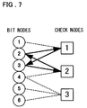
- a Turner graph defined by a check matrix H of an equation (5) includes a loop of length 4 as shown in FIG. 7 .
- arrows indicate the direction of each message passed between nodes.
- the path of the loop of length 4 is from a check node 1 to a bit node 3 , from the bit node 3 to a check node 2 , from the check node 2 to a bit node 2 , and from the bit node 2 to the check node 1 .
- Non-Patent Document 1 When a message goes around as above, accurate posterior probability cannot be computed by the decoder, resulting in deteriorated decoding characteristics. It is known that the shorter the loop is, the worse decoding characteristics become (Non-Patent Document 1).
- a majority of the chip area is occupied by a register or memory for holding messages and interconnect paths for sending/receiving messages.
- Non-Patent Document 2 a method for reducing the number of messages by approximating the equation (2) by an equation (6) has been proposed.
- R mn refers to messages from the check node m to the bit node n and can be given by the equation (3).
- S(k) of m′ ⁇ S(k) ⁇ (n) ⁇ in ( ⁇ R m′n ), the summing operation of R m′n about m′, is a set of check nodes included in the cluster being computed at a time k
- ⁇ (n) is a set of check nodes adjacent to the bit node n
- ⁇ represents AND.
- the messages R m′n from a check node m′ that is included in both S(k) and ⁇ (n) are summed, Q n (k ⁇ 1) at a previous time k ⁇ 1 is added to the summed result, and Q′ n (k), the message at the time k, is the result of this addition.
- the bit node n passes the same message Q′ n (k) to the check nodes connected to the bit node n.
- the messages R mn from the check node m to the bit node n are computed for each cluster, and the computation results are added to Q′ n .
- the initial value Q′ n (0) of Q′ n (k) is the input (channel) LLR.
- y I is the received symbol
- x I is the transmitted symbol
- binary-bipolar conversion (0 ⁇ +1, 1 ⁇ 1) is executed.
- one bit node sends the same message to all the adjacent check nodes (all the check nodes connected to the bit node). Therefore, resources such as registers for holding messages and interconnect paths can be greatly reduced.
- the amount of message computations can be reduced by 50 percent or more, compared to the equation (2). In other words, the computation speed and processing performance are improved.
- the messages R mn that the check node m sends to the bit node n are sent back to the check node m even when no loop exists in the Turner graph.
- posterior probability cannot be computed accurately, resulting in the deterioration of the error correction performance.
- FIGS. 8A and 8B are drawings illustrating the operation timing of message computations.
- FIG. 8A is a drawing illustrating the operation timing when there is no delay in message computation at the check nodes
- FIG. 8B is a drawing illustrating the operation timing when there is a processing delay of 2 clock cycles in message computation at the check nodes.
- input message is the input message from the bit node 1 to each check node in FIGS. 5 and 6 .
- Computation clusters C 1 , C 2 , and C 3 represent first, second, and third clusters, and output message represents the message outputted by the corresponding cluster.
- the check node 1 is grouped as the first cluster (C 1 ), the check node 2 as the second cluster (C 2 ), and the check node 3 as the third cluster (C 3 ).
- the first, second, and third clusters are the check nodes 1 , 2 , and 3 respectively in FIGS. 5 , 6 , 8 A and 8 B.
- “RCYX” in the drawing represents the output of an X th cluster in a Y th iteration.
- “L” in the input message is the value of the input LLR.
- a message sent by a check node is passed back to the original check node even if no loop exists in the Turner graph.
- an output RC 11 of the first cluster C 1 in a first iteration (the output of the first cluster in the first iteration and its content is a message R 11 from the check node 1 to the bit node 1 ) is passed back to the first cluster C 1 (the check node 1 ) in the ensuing second iteration (refer to FIGS. 8A and 8B ).
- the messages that the first cluster C 1 receives in the second iteration are L+RC 11 +RC 12 +RC 13 (refer to FIG. 8A ).
- L is the value of the input LLR.
- they are L+RC 11 in the second iteration (refer to FIG. 8B ), increasing the ratio (proportion) of RC 11 , i.e., the output message of the first cluster C 1 . Because of this, the error correction performance and decoding characteristics will deteriorate.
- a decoding device that decodes a received low density parity check code by repeating the passing of messages between a plurality of check nodes and a plurality of bit nodes corresponding to a low density parity check matrix in each iteration.
- the decoding device comprises means (scheduler) that varies the order of message computation at the check nodes in one of at least two iterations that have a before-and-after relationship in time and the order of message computation at the check nodes in another iteration.
- the scheduler assigns a cluster index to a cluster to be computed at the Y th order in an X th iteration as follows: (((Y ⁇ 1)+(X ⁇ 1)*(N ⁇ D))% N)+1
- the bit node may comprise a control unit that weights (or means for weighting) a message sent to the bit node from the check node.
- a bit node passes the same message to all check nodes connected to the same bit node and that the ratio of a message outputted by the check node within messages sent to the check node is reduced.
- the bit node may comprise a holding unit that holds a message received from the check node, multiplies the held message by a weight of a positive number smaller than 1 every time the bit node receives a message from the check node thereafter, and holds the multiplication result.
- the bit node when it receives a message for the i th time (where i is a positive number not less than 2) from the check node, it may compute a message to be sent to the check node based on the multiplication of a message received from the check node for the j th time (where j is an integer greater than or equal to 1, but less than i) by w (i-j) (where w is the weighted coefficient) and the message received for the i th time (where i is a positive number not less than 2).
- a decoding method wherein a received low density parity check code is decoded by repeating the passing of messages between a plurality of check nodes and a plurality of bit nodes corresponding to a low density parity check matrix in each iteration, and including a step of varying the order of message computation at the check nodes in one of at least two iterations that have a before-and-after relationship in time and the order of message computation at the check nodes in another iteration.
- a computer-readable program that has a computer, which decodes a received low density parity check code by repeating the passing of messages between a plurality of check nodes and a plurality of bit nodes corresponding to a low density parity check matrix in each iteration, execute processing for varying the order of message computation at the check nodes in one of at least two iterations that have a before-and-after relationship in time and the order of message computation at the check nodes in another iteration.
- the program is stored in a machine-readable medium by a computer.
- the decoding characteristics can be improved by varying the order of message computation in at least two iterations that have a before-and-after relationship in time and reducing the ratio of a message from a check node within messages sent to the same check node.
- the decoding characteristics can be improved by weighting a message so that the longer ago the message is computed, the less influential it becomes.
- FIG. 1 is a drawing for explaining an embodiment of the present invention.
- FIG. 2 is a drawing for explaining the operation of the first embodiment of the present invention.
- FIG. 3 is a drawing for explaining the operation of another embodiment of the present invention.
- FIG. 4 is a drawing showing an embodiment of a device of the present invention.
- FIG. 5 is an example of a Turner graph.
- FIG. 6 is a drawing illustrating how messages are passed when the cluster size is 1.
- FIG. 7 is a Turner graph having a loop.
- FIGS. 8A and 8B are timing charts time-sequentially showing messages passed between bit nodes and clusters.
- the two iterations may be consecutive in time.
- the order of message computation may be switched in each iteration.
- the present invention comprises a control unit that controls the ratio of a message R mn outputted by a check node m within messages passed from a bit node to the check node m to be small in addition to the aforementioned scheduling unit.
- the message R mn is weighted so that the longer ago it was computed at a check node, the less influential the message R mn that has already been outputted by the check node m becomes within the message Qn passed from the bit node n to the check node m.
- FIG. 1 is a drawing for explaining the present embodiment.
- the 10 ⁇ 3 check matrix H of the equation (1) comprises ten bit nodes (first to tenth bit node message computation units) and three check nodes (first to third check node message computation units).
- Input LLRs Log Likelihood Ratio supplied to the first to tenth bit node message computation units are channel LLRs.
- the message R mn from the check node m to the bit node n is computed for each cluster, and the results are added to Q′ n .
- one bit node sends the same message to all the adjacent check nodes, greatly reducing registers for holding messages and interconnect paths.
- the computation of messages from the bit nodes to the check node(s) is performed using the approximation by the equation (6), and a bit node outputs the same message Q′ n (k) to all the check nodes connected to the bit node. Further, the equation (2) is used for the computation of the message R mn from the check node m to the bit node n.
- FIGS. 8 A and 8 B show the case where the cluster size is 1 and the three check nodes correspond to the clusters C 1 to C 3 , respectively.
- the messages sent from the bit node 1 to the check node 1 grouped as the cluster C 1 in the second iteration are L+RC 11 , increasing the ratio of the message RC 11 computed at the check node 1 grouped as the cluster C 1 in the first iteration. This will deteriorate decoding characteristics.
- the present embodiment comprises a scheduling unit (a scheduler described later) that varies the order of message computation at the check nodes in one (for instance the first iteration) of at least two iterations that have a before-and-after relationship in time and the order of message computation at the check nodes in another iteration (for instance the second iteration).
- a scheduling unit a scheduler described later
- FIG. 2 is a timing chart for explaining the operation of the first embodiment of the present invention.
- the cluster size is 1 and the three check nodes are divided into three clusters C 1 , C 2 , and C 3 .
- C 1 , C 2 , and C 3 correspond to the check nodes 1 , 2 , and 3 respectively.
- the processing delay in message computation at the check nodes is 2 clock cycles.
- messages are computed in the order of C 1 , C 2 and C 3 .
- the message RC 11 of the cluster C 1 in the first iteration is outputted to the bit node 1 when the message of the cluster C 3 is computed.
- a message RC 12 of the cluster C 2 in the first iteration is outputted to the bit node 1 , after the delay of 2 clock cycles, when the messages of the cluster C 2 in the second iteration is computed.
- a message RC 13 of the cluster C 3 in the first iteration is outputted to the bit node 1 , after the delay of 2 clock cycles, when the messages of the cluster C 3 in the second iteration is computed.
- the cluster C 2 receives messages L+RC 11 computed at the bit node 1 based on the equation (6).
- the input messages L+RC 11 do not include the message RC 12 computed at the cluster C 2 (the check node 2 ), therefore there is no short loop.
- messages L+RC 11 +RC 12 are computed based on the equation (6) at the bit node 1 who has received the message RC 12 from the cluster C 2 , and the messages L+RC 11 +RC 12 are supplied to the cluster C 3 .
- the input messages L+RC 11 +RC 12 do not include the message RC 13 computed at the cluster C 3 (the check node 3 ), therefore there is no short loop.
- messages L+RC 11 +RC 12 +RC 13 are computed based on the equation (6) at the bit node 1 who has received the message RC 13 from the cluster C 3 , and the messages L+RC 11 +RC 12 +RC 13 are supplied to the cluster C 1 .
- the input messages L+RC 11 +RC 12 +RC 13 include the message RC 11 computed at the cluster C 1 (the check node 1 ), however, it is merely a part of the messages L+RC 11 +RC 12 +RC 13 and not a part of L+RC 11 as in the case shown in FIG. 8B . Therefore its influence is reduced and decoding characteristics are improved compared to the case shown in FIG. 8B .
- the order of the clusters at which messages are computed is varied in each iteration.
- the order of the clusters at which messages are computed is varied as in the first embodiment, and decoding characteristics are improved by weighting a message so that the longer ago the message is computed at a check node, the less influential it becomes within messages sent to the check node.
- the computation of messages from the bit nodes to the check nodes is basically performed using the approximation by the equation (6), and a bit node outputs the same message Q′ n (k) (where k is discrete time) to all the check nodes connected to the bit node.
- the equation (3) is used for the computation of the message R mn from the check node m to the bit node n.
- w denotes the weighted coefficient (a positive number smaller than 1).
- the bit node n holds LLR and a property QS n (k) at a time k, and sends Q′ n (k), the result of adding them, to all the adjacent check nodes (refer to the equation (8)).
- QSn( 0 ) the initial value of QS n (k), is 0.
- the property QS n (k) is updated by adding the total sum ( ⁇ R m′n ) of the messages R m′n received this time to the multiplication of QS n (k ⁇ 1) at the previous time (a time k ⁇ 1) by a weight w (QS n (k ⁇ 1)*w). (Refer to the equation (9).
- the order of the message computations at the check node message computation units is varied in each iteration, and decoding characteristics are improved by weighting a message so that the longer ago the message is computed at a check node, the less influential it becomes within messages sent to the check node.
- the second embodiment of the present invention will be described using the LDPC code defined by the 10 ⁇ 3 check matrix H of the equation (1).
- the 10 ⁇ 3 check matrix H of the equation (1) comprises ten bit nodes (first to tenth bit node message computation units) and three check nodes (first to third check node message computation units) as shown in FIG. 1 .
- Input LLRs Log Likelihood Ratio supplied to the first to tenth bit node message computation units are channel LLRs.
- the message R mn from the check node m to the bit node n is computed for each cluster, and the results are added to Q′ n .
- one bit node sends the same message to all the adjacent check nodes, greatly reducing registers for holding messages and interconnect paths.
- n is any number from 1 to 10
- the equations (8) and (9) are used for the computation of messages from the bit node n to the check nodes.
- An m th check node message computation unit (m is any number from 1 to 3) computes the message R mn from the check node m to the bit node n according to the equation (3).
- FIG. 3 is a drawing for explaining the operation timing when the cluster size is set to 1 in FIG. 1 (one check node per cluster) and the three check nodes are divided into three clusters.
- the delay in message computation at the check nodes is 2 clock cycles.
- messages are computed in the order of C 1 , C 2 and C 3 .
- a message RC 11 of the cluster C 1 in the first iteration is outputted to the bit node 1 when the message of the cluster C 2 is computed.
- a message RC 12 of the cluster C 2 in the first iteration is outputted to the bit node 1 , after the delay of 2 clock cycles, when the messages of the cluster C 2 in the second iteration is computed.
- a message RC 13 of the cluster C 3 in the first iteration is outputted to the bit node 1 , after the delay of 2 clock cycles, when the messages of the cluster C 3 in the second iteration is computed.
- the cluster C 2 receives messages L+RC 11 computed at the bit node 1 .
- the input messages L+RC 11 do not include the message RC 12 computed at the cluster C 2 (the check node 2 ), therefore there is no short loop.
- messages L+RC 11 *w+RC 12 are computed based on the equations (8) and (9) at the bit node 1 who has received the message RC 12 from the cluster C 2 , and the messages L+RC 11 *w+RC 12 are supplied to the cluster C 3 .
- the input messages L+RC 11 *w+RC 12 do not include the message RC 13 computed at the cluster C 3 (the check node 3 ), therefore there is no short loop.
- messages L+RC 11 *w 2 +RC 12 *w+RC 13 are computed based on the equations (8) and (9) at the bit node 1 who has received the message RC 13 from the cluster C 3 , and the messages L+RC 11 *w 2 +RC 12 *w+RC 13 are supplied to the cluster C 1 .
- the input messages L+RC 11 *w 2 +RC 12 *w+RC 13 include the message RC 11 computed at the cluster C 1 (the check node 1 ), however, it is merely a part of the messages L+RC 11 *w 2 +RC 12 *w+RC 13 and is multiplied by the square of the weighted coefficient w (RC 11 *w 2 ) further decreasing the ratio of the message RC 11 .
- FIG. 4 is a diagram illustrating the structure of a decoder circuit of an embodiment of the present invention.
- the circuit comprises n bit node message computation units 1 1 to 1 n , a scheduler 8 , an MCU 9 (Message Computation Unit: also called “check node message computation unit”), and an output selector 10 .
- the scheduler 8 selects a check node to which the bit node message computation units 1 1 to 1 n output messages.
- the MCU 9 is a controller that constitutes the check nodes.
- the output of the MCU 9 is forwarded to a bit node message computation unit selected from the bit node message computation units 1 1 to 1 n via the output selector 10 .
- the cluster size of the structure shown in FIG. 4 is 1.
- the bit node message computation unit 1 1 comprises a selector 2 , an adder 3 , a multiplier 4 , a register 5 , a register 7 , and an adder 6 .
- the register 7 holds the input LLR.
- the adder 6 adds the value of the register 5 (Reg 1 ) and the input LLR (an output of the register 7 ). Note that all the n bit node message computation units 1 1 to 1 n are structured identically.
- the multiplier 4 multiplies the output of the register 5 (Reg 1 ) by the weighted coefficient w.
- the multiplier 4 outputs QS n (k ⁇ 1)*w (refer to the equation (9)).
- the adder 3 adds the output of the multiplier 4 (QS n (k ⁇ 1)*w) and the message R m′n from the MCU 9 , derives the property QS n (k) at this time (the time k)—refer to the equation (9)—, and updates the register 5 .
- the MCU 9 pays attention to (and the bit node n receives) only one message since the cluster size is 1 in the present embodiment. Therefore the adding operation of ⁇ R m′n (refer to the equation (9)) is not performed.
- the adder 3 adds the addition result ( ⁇ R m′n ) of multiple messages from the MCU 9 to the output of the multiplier 4 (QS n (k ⁇ 1)*w).
- the adder 6 performs the addition LLR+QS n (k) and outputs the result as Q′ n (k) (refer to the equation (8)).
- the scheduler 8 switches the order of message computation at the clusters (the check nodes) in each iteration. For instance, as shown in FIGS. 2 and 3 , the order is variable-controlled as follows: C 1 , C 2 , and C 3 in the first iteration, C 2 , C 3 , and C 1 in the second iteration, and C 3 , C 1 , and C 2 in the third iteration. Further, the scheduler 8 functions as a switch for supplying messages from a bit node to all check nodes connected to the bit node. For instance, it selects a path for messages from the bit nodes to the check nodes in the message passing shown in FIG. 6 .
- the MCU 9 computes the message R mn based on the equation (3) and outputs it.
- the output selector 10 distributes the message from the MCU 9 to the destination bit node.
- the output selector 10 selects a path for messages from the check nodes to the bit nodes, for instance, in the message passing shown in FIG. 5 .
- the structure shown in FIG. 3 in which the value of the weighted coefficient w is 1 (or in which the multiplier 4 is omitted) corresponds to the structure of the first embodiment of the present invention described with reference to FIG. 2 .
- the structure in which the weighted coefficient w is 0 ⁇ w ⁇ 1 corresponds to the second embodiment described with reference to FIG. 3 .
- An input “0” of the selector 2 is an input for initializing the register 5 in the summing operation of the equation (9).
- the output of the adder 6 is L, which is the value of the input LLR, and a message L is supplied to a check node.
- the output of the multiplier 4 is 0.
- the output of the adder 3 is RC 11 when it receives the message RC 11 sent by the check node. Since the selector 2 selects the output of the adder 3 , RC 11 is stored in the register 5 , the adder 6 adds the value L of the input LLR to RC 11 , and messages L+RC 11 are outputted to the check node.
- RC 11 *w the result of multiplying RC 11 , the output of the register 5 , by w by the multiplier 4 , is added to the message RC 12 from the cluster C 2 (the check node 2 ).
- the result RC 11 *w+RC 12 is selected by the selector 2 and held by the register 5 .
- the adder 6 outputs messages L+RC 11 *w+RC 12 .
- the weight accumulation process is performed similarly thereafter, and the bit node 1 supplies L+RC 11 *w 2 +RC 12 *w+RC 13 to the check node 1 in the second iteration.
- processings of the registers, the selector, the adders, and the multiplier of the bit node message unit shown in FIG. 4 may be realized by a program executed by a computer.
- the processings of the scheduler, the MCU, and the output selector may be performed by a computer program.
- This computer program is stored in a machine-readable medium, load into main memory and executed by a computer.
Landscapes
- Physics & Mathematics (AREA)
- Probability & Statistics with Applications (AREA)
- Engineering & Computer Science (AREA)
- Theoretical Computer Science (AREA)
- Error Detection And Correction (AREA)
- Detection And Correction Of Errors (AREA)
- Detection And Prevention Of Errors In Transmission (AREA)
Abstract
Description
- Japanese Patent Kokai Publication No. JP-P2003-244109A
[Non-Patent Document 1] - D. J. C. MacKay, “Good error-correcting codes based on very sparse matrices,” IEEE Transactions on Information Theory, vol. 45, pp. 399-431 (1999).
[Non-Patent Document 2] - Yeo, E.; Pakzad, P.; Nikolic, B.; Anantharam, V., “High throughput low-density parity-check decoder architectures,” Global Telecommunications Conference 2001, Volume: 5, 25-29 Nov. 2001, pp. 3019-3024.
(((Y−1)+(X−1)*(N−D))% N)+1
(((Y−1)+(X−1)*(N−D))% N)+1 (7)
Q′ n(k)=LLR+QS n(k) (8)
Claims (24)
((Y−1)+(X−1)*(N−D))% N)+1,
((Y−1)+(X−1)*(N−D))% N)+1,
(((Y−1)+(X−1)*(N−D))% N)+1,
Applications Claiming Priority (2)
| Application Number | Priority Date | Filing Date | Title |
|---|---|---|---|
| JP2005-191153 | 2005-06-30 | ||
| JP2005191153A JP4526451B2 (en) | 2005-06-30 | 2005-06-30 | Decoding apparatus, method, and program |
Publications (2)
| Publication Number | Publication Date |
|---|---|
| US20070033481A1 US20070033481A1 (en) | 2007-02-08 |
| US7805654B2 true US7805654B2 (en) | 2010-09-28 |
Family
ID=37718942
Family Applications (1)
| Application Number | Title | Priority Date | Filing Date |
|---|---|---|---|
| US11/476,679 Expired - Fee Related US7805654B2 (en) | 2005-06-30 | 2006-06-29 | Decoding device and decoding method and program |
Country Status (2)
| Country | Link |
|---|---|
| US (1) | US7805654B2 (en) |
| JP (1) | JP4526451B2 (en) |
Cited By (7)
| Publication number | Priority date | Publication date | Assignee | Title |
|---|---|---|---|---|
| US20100042895A1 (en) * | 2008-08-15 | 2010-02-18 | Lsi Corporation | Selecting layered-decoding schedules for offline testing |
| US20130132790A1 (en) * | 2011-11-22 | 2013-05-23 | Lsi Corporation | Probability-Based Multi-Level LDPC Decoder |
| WO2014197757A1 (en) | 2013-06-07 | 2014-12-11 | Alcatel Lucent | Error correction for entangled quantum states |
| US9195536B2 (en) | 2013-07-05 | 2015-11-24 | Kabushiki Kaisha Toshiba | Error correction decoder and error correction decoding method |
| WO2015195325A1 (en) | 2014-06-18 | 2015-12-23 | Alcatel-Lucent Usa Inc. | Hardware-efficient syndrome extraction for entangled quantum states |
| US9944520B2 (en) | 2013-01-15 | 2018-04-17 | Alcatel Lucent | Syndrome of degraded quantum redundancy coded states |
| US10069515B2 (en) | 2015-02-02 | 2018-09-04 | Kabushiki Kaisha Toshiba | Decoding device and decoding method |
Families Citing this family (2)
| Publication number | Priority date | Publication date | Assignee | Title |
|---|---|---|---|---|
| US7647548B2 (en) * | 2006-07-31 | 2010-01-12 | Agere Systems Inc. | Methods and apparatus for low-density parity check decoding using hardware-sharing and serial sum-product architecture |
| FR2912574B1 (en) * | 2007-02-13 | 2010-09-17 | Commissariat Energie Atomique | METHOD FOR DECODING MESSAGE PASSAGE AND FORCED CONVERGENCE. |
Citations (8)
| Publication number | Priority date | Publication date | Assignee | Title |
|---|---|---|---|---|
| JP2003244109A (en) | 2002-02-13 | 2003-08-29 | Mitsubishi Electric Corp | Communication system, receiver, transmitter and communication method |
| JP2004186940A (en) | 2002-12-03 | 2004-07-02 | Nec Corp | Error correction code decoding device |
| US20050138516A1 (en) * | 2003-12-04 | 2005-06-23 | Yedidia Jonathan S. | Decoding Reed-Solomon codes and related codes represented by graphs |
| US20050268204A1 (en) | 2004-05-31 | 2005-12-01 | Kabushiki Kaisha Toshiba | Decoding apparatus and decoding circuit |
| WO2006059688A1 (en) | 2004-12-02 | 2006-06-08 | Mitsubishi Denki Kabushiki Kaisha | Decoding device and communication device |
| WO2006120844A1 (en) | 2005-05-13 | 2006-11-16 | Nec Corporation | Encoder and decoder by ldpc encoding |
| JP2007013518A (en) | 2005-06-30 | 2007-01-18 | Nec Electronics Corp | Decoding apparatus and method, and program |
| US20070113163A1 (en) * | 2003-11-26 | 2007-05-17 | Matsushita Electric Industrial Co., Ltd. | Belief propagation decoder cancelling the exchange of unreliable messages |
-
2005
- 2005-06-30 JP JP2005191153A patent/JP4526451B2/en not_active Expired - Fee Related
-
2006
- 2006-06-29 US US11/476,679 patent/US7805654B2/en not_active Expired - Fee Related
Patent Citations (13)
| Publication number | Priority date | Publication date | Assignee | Title |
|---|---|---|---|---|
| US20040185886A1 (en) | 2002-02-13 | 2004-09-23 | Wataru Matsumoto | Communication system, receiver, transimtter and communication method |
| JP2003244109A (en) | 2002-02-13 | 2003-08-29 | Mitsubishi Electric Corp | Communication system, receiver, transmitter and communication method |
| JP2004186940A (en) | 2002-12-03 | 2004-07-02 | Nec Corp | Error correction code decoding device |
| US7373581B2 (en) | 2002-12-03 | 2008-05-13 | Nec Corporation | Device, program, and method for decoding LDPC codes |
| US20070113163A1 (en) * | 2003-11-26 | 2007-05-17 | Matsushita Electric Industrial Co., Ltd. | Belief propagation decoder cancelling the exchange of unreliable messages |
| US20050138516A1 (en) * | 2003-12-04 | 2005-06-23 | Yedidia Jonathan S. | Decoding Reed-Solomon codes and related codes represented by graphs |
| US20050268204A1 (en) | 2004-05-31 | 2005-12-01 | Kabushiki Kaisha Toshiba | Decoding apparatus and decoding circuit |
| JP2005347883A (en) | 2004-05-31 | 2005-12-15 | Toshiba Corp | Decoding device and decoding circuit |
| WO2006059688A1 (en) | 2004-12-02 | 2006-06-08 | Mitsubishi Denki Kabushiki Kaisha | Decoding device and communication device |
| US20080246639A1 (en) | 2004-12-02 | 2008-10-09 | Mitsubishi Denki Kabushiki Kaisha | Decoding Apparatus and Communications Apparatus |
| WO2006120844A1 (en) | 2005-05-13 | 2006-11-16 | Nec Corporation | Encoder and decoder by ldpc encoding |
| US20070033482A1 (en) | 2005-06-30 | 2007-02-08 | Nec Electronics Corporation | Decoder device and decoding method and program |
| JP2007013518A (en) | 2005-06-30 | 2007-01-18 | Nec Electronics Corp | Decoding apparatus and method, and program |
Non-Patent Citations (3)
| Title |
|---|
| D. Mackay, "Good Error-Correcting Codes Based on Very Sparse Matrices," IEEE Transactions on Information Theory, vol. 45:2, Mar. 1999, pp. 399-431. |
| E. Yeo et al., "High Throughput Low-Density Parity-Check Decoder Architectures," Global Telecommunications Conference 2001, vol. 5, 25-29, Nov. 2001, pp. 3019-3024. |
| Yoshihiro Kurihara et al. Performance Evaluation of Ordered Sum-Product Algorithm, The Institute of Electronics, Information And Communication Engineers Research Report, Mar. 9, 2004, pp. 13-18. |
Cited By (14)
| Publication number | Priority date | Publication date | Assignee | Title |
|---|---|---|---|---|
| US20100042896A1 (en) * | 2008-08-15 | 2010-02-18 | Lsi Corporation | Error-floor mitigation of layered decoders using non-standard layered-decoding schedules |
| US8495449B2 (en) * | 2008-08-15 | 2013-07-23 | Lsi Corporation | Selecting layered-decoding schedules for offline testing |
| US8555129B2 (en) | 2008-08-15 | 2013-10-08 | Lsi Corporation | Error-floor mitigation of layered decoders using non-standard layered-decoding schedules |
| US20100042895A1 (en) * | 2008-08-15 | 2010-02-18 | Lsi Corporation | Selecting layered-decoding schedules for offline testing |
| US20130132790A1 (en) * | 2011-11-22 | 2013-05-23 | Lsi Corporation | Probability-Based Multi-Level LDPC Decoder |
| US8719686B2 (en) * | 2011-11-22 | 2014-05-06 | Lsi Corporation | Probability-based multi-level LDPC decoder |
| US9944520B2 (en) | 2013-01-15 | 2018-04-17 | Alcatel Lucent | Syndrome of degraded quantum redundancy coded states |
| US10633248B2 (en) | 2013-01-15 | 2020-04-28 | Alcatel Lucent | Syndrome of degraded quantum redundancy coded states |
| WO2014197757A1 (en) | 2013-06-07 | 2014-12-11 | Alcatel Lucent | Error correction for entangled quantum states |
| US9286154B2 (en) | 2013-06-07 | 2016-03-15 | Alcatel Lucent | Error correction for entangled quantum states |
| US9195536B2 (en) | 2013-07-05 | 2015-11-24 | Kabushiki Kaisha Toshiba | Error correction decoder and error correction decoding method |
| US9762262B2 (en) | 2014-06-18 | 2017-09-12 | Alcatel Lucent | Hardware-efficient syndrome extraction for entangled quantum states |
| WO2015195325A1 (en) | 2014-06-18 | 2015-12-23 | Alcatel-Lucent Usa Inc. | Hardware-efficient syndrome extraction for entangled quantum states |
| US10069515B2 (en) | 2015-02-02 | 2018-09-04 | Kabushiki Kaisha Toshiba | Decoding device and decoding method |
Also Published As
| Publication number | Publication date |
|---|---|
| JP2007013519A (en) | 2007-01-18 |
| US20070033481A1 (en) | 2007-02-08 |
| JP4526451B2 (en) | 2010-08-18 |
Similar Documents
| Publication | Publication Date | Title |
|---|---|---|
| US7181676B2 (en) | Layered decoding approach for low density parity check (LDPC) codes | |
| US7343548B2 (en) | Method and apparatus for encoding and decoding data | |
| US10951235B2 (en) | Low density parity check decoder | |
| US7137060B2 (en) | Forward error correction apparatus and method in a high-speed data transmission system | |
| US7539920B2 (en) | LDPC decoding apparatus and method with low computational complexity algorithm | |
| US6751770B2 (en) | Decoder for iterative decoding of binary cyclic codes | |
| US8266493B1 (en) | Low-density parity check decoding using combined check node and variable node | |
| US7895500B2 (en) | Systems and methods for reduced complexity LDPC decoding | |
| US8281205B2 (en) | LDPC decoding apparatus, decoding method and program | |
| US8245116B2 (en) | Method for performing soft decision decoding of Euclidean space Reed-Muller codes | |
| US7937648B2 (en) | Decoding device, control method, and program | |
| US20090106621A1 (en) | Data decoding apparatus, data decoding method, data transmitting/receiving system, data receiving apparatus, data receiving method and program | |
| US7707476B2 (en) | Decoder device and decoding method and program | |
| US7805654B2 (en) | Decoding device and decoding method and program | |
| US10439643B2 (en) | Reed-Solomon decoders and decoding methods | |
| CN101154948A (en) | Methods and apparatus for low-density parity check decoding using hardware-sharing and serial sum-product architecture | |
| JP4519694B2 (en) | LDPC code detection apparatus and LDPC code detection method | |
| US8166363B2 (en) | Decoding device and method | |
| US7725801B2 (en) | Method of generating quasi-cyclic low density parity check codes and an apparatus thereof | |
| CN112865812B (en) | Multi-element LDPC decoding method, computer storage medium and computer | |
| US8572462B2 (en) | Decoding apparatus and decoding method | |
| TWI381652B (en) | Method for generating parity-check matrix | |
| Habib et al. | Sequential interval passing for compressed sensing | |
| Zhang | Further exploring the strength of prediction in the factorization of soft-decision Reed–Solomon decoding | |
| US20220385310A1 (en) | Method and device for energy-efficient decoders |
Legal Events
| Date | Code | Title | Description |
|---|---|---|---|
| AS | Assignment |
Owner name: NEC ELECTRONICS CORPORATION, JAPAN Free format text: ASSIGNMENT OF ASSIGNORS INTEREST;ASSIGNOR:SEKI, KATSUTOSHI;REEL/FRAME:018056/0358 Effective date: 20060622 |
|
| AS | Assignment |
Owner name: RENESAS ELECTRONICS CORPORATION, JAPAN Free format text: CHANGE OF NAME;ASSIGNOR:NEC ELECTRONICS CORPORATION;REEL/FRAME:025311/0842 Effective date: 20100401 |
|
| FEPP | Fee payment procedure |
Free format text: PAYOR NUMBER ASSIGNED (ORIGINAL EVENT CODE: ASPN); ENTITY STATUS OF PATENT OWNER: LARGE ENTITY |
|
| REMI | Maintenance fee reminder mailed | ||
| LAPS | Lapse for failure to pay maintenance fees | ||
| STCH | Information on status: patent discontinuation |
Free format text: PATENT EXPIRED DUE TO NONPAYMENT OF MAINTENANCE FEES UNDER 37 CFR 1.362 |
|
| STCH | Information on status: patent discontinuation |
Free format text: PATENT EXPIRED DUE TO NONPAYMENT OF MAINTENANCE FEES UNDER 37 CFR 1.362 |
|
| FP | Lapsed due to failure to pay maintenance fee |
Effective date: 20140928 |