US7805077B2 - Scalable and movable DWDM usage of CWDM networks - Google Patents
Scalable and movable DWDM usage of CWDM networks Download PDFInfo
- Publication number
- US7805077B2 US7805077B2 US10/889,333 US88933304A US7805077B2 US 7805077 B2 US7805077 B2 US 7805077B2 US 88933304 A US88933304 A US 88933304A US 7805077 B2 US7805077 B2 US 7805077B2
- Authority
- US
- United States
- Prior art keywords
- cwdm
- dwdm
- signal
- optical
- multiplexed
- Prior art date
- Legal status (The legal status is an assumption and is not a legal conclusion. Google has not performed a legal analysis and makes no representation as to the accuracy of the status listed.)
- Active, expires
Links
Images


Classifications
-
- H—ELECTRICITY
- H04—ELECTRIC COMMUNICATION TECHNIQUE
- H04J—MULTIPLEX COMMUNICATION
- H04J14/00—Optical multiplex systems
- H04J14/02—Wavelength-division multiplex systems
- H04J14/0201—Add-and-drop multiplexing
- H04J14/0202—Arrangements therefor
- H04J14/0213—Groups of channels or wave bands arrangements
-
- H—ELECTRICITY
- H04—ELECTRIC COMMUNICATION TECHNIQUE
- H04J—MULTIPLEX COMMUNICATION
- H04J14/00—Optical multiplex systems
- H04J14/02—Wavelength-division multiplex systems
- H04J14/0201—Add-and-drop multiplexing
- H04J14/0202—Arrangements therefor
- H04J14/021—Reconfigurable arrangements, e.g. reconfigurable optical add/drop multiplexers [ROADM] or tunable optical add/drop multiplexers [TOADM]
-
- H—ELECTRICITY
- H04—ELECTRIC COMMUNICATION TECHNIQUE
- H04J—MULTIPLEX COMMUNICATION
- H04J14/00—Optical multiplex systems
- H04J14/02—Wavelength-division multiplex systems
- H04J14/0201—Add-and-drop multiplexing
- H04J14/0215—Architecture aspects
- H04J14/0216—Bidirectional architectures
Definitions
- the present invention relates generally to multiplexed high speed communications systems, methods, and devices. More particularly, embodiments of the invention relate to systems and methods for transparently providing scalable and movable DWDM usage onto CWDM networks.
- Computer and data communications networks continue to develop and expand due to declining costs, improved performance of computer and networking equipment, the remarkable growth of the internet, and the resulting increased demand for communication bandwidth.
- Such increased demand is occurring both within and between metropolitan areas as well as within communications networks, such as wide area networks (“WANs”), metropolitan area networks (“WANs”), and local area networks (“LANs”).
- WANs wide area networks
- WANs metropolitan area networks
- LANs local area networks
- digital data in the form of light signals is formed by light emitting diodes or lasers and then propagated through a fiber optic cable.
- Such light signals allow for high data transmission rates and high bandwidth capabilities.
- Other advantages of using light signals for data transmission include their resistance to electro-magnetic radiation that interferes with electrical signals; fiber optic cables' ability to prevent light signals from escaping, as can occur electrical signals in wire-based systems; and light signals' ability to be transmitted over great distances without the signal loss typically associated with electrical signals on copper wire.
- wavelength division multiplexing WDM
- demuxes demultiplexers
- multiplexers multiplexers
- mux/demux modules optical add drop multiplexers
- a demultiplexer generally takes as its input an optical transmission that includes a number of individual signals, with each signal being transmitted using a particular wavelength of light.
- An exemplary optical demultiplexer is shown in FIG. 1 and designated generally as 100 .
- the optical demultiplexer 100 has an input port 102 .
- the input port 102 receives a multiplexed transmission 104 .
- the multiplexed transmission 104 has four individual signals, each of different wavelengths, which are designated in this example as ⁇ 1 , ⁇ 2 , ⁇ 3 , and ⁇ 4 , as indicated in FIG. 1A .
- the optical demultiplexer 100 is a passive device, meaning that no external power or control is needed to operate the device.
- the optical demultiplexer 100 is a passive device, it should be noted that active devices can be used in optical demultiplexing as well. Using a combination of passive components, such as thin-film three-port devices, mirrors, birefringent crystals, etc., the optical demultiplexer 100 separates the multiplexed signal 104 into its constituent parts. Each of the individual wavelengths, each representing a separate signal on a communication channel, is then output to one of output ports 106 , 108 , 110 , 112 .
- passive components such as thin-film three-port devices, mirrors, birefringent crystals, etc.
- a multiplexer functions in the inverse manner as the demultiplexer. Multiplexers can often be constructed from demultiplexers simply by using the output ports 106 , 108 , 110 , 112 as input ports and the input port 102 as an output port.
- An optical device that combines the functionality of a demultiplexer and a multiplexer is known as a mux/demux.
- An exemplary mux/demux is shown in FIG. 2 and designated generally as 200 .
- the mux/demux 200 has a multiplexed input port 202 that accepts as its input a multiplexed transmission 104 .
- the multiplexed transmission 104 is separated into its constituent parts and output to demultiplexed output ports 204 , 206 , 208 , 210 .
- demultiplexed input ports 212 , 214 , 216 , 218 accept as their input individual signals, with each signal being encoded on a different optical wavelength.
- the individual signals are combined into a multiplexed transmission and output to the multiplexed output 220 from output port 105 .
- An OADM is a component designed to extract an individual signal from the multiplexed transmission while allowing the remaining signals on the multiplexed transmission to pass through.
- the OADM also has an add port that can be used to remix the extracted signal with the multiplexed transmission or to transmit other data onto the fiber-optic network.
- An example of an OADM is shown in FIG. 3 and designated generally as 300 .
- the OADM 300 is designed for bi-directional data communication. In optical networks, to distinguish the direction of data travel, the directions are referred to as east and west directions. In FIG. 3 , data that travels in an easterly direction travels to the right of the OADM 300 . Data the travels in a westerly direction travels to the left of the OADM 300 .
- a multiplexed transmission 104 is input into the east input port 302 .
- the OADM 300 is designed for a specific wavelength or, more precisely, a band of wavelengths. For example, if the particular multiplexed transmission has four wavelengths, including a 1510 nanometer wavelength, a 1530 nanometer wavelength, a 1550 nanometer wavelength, and a 1570 nanometer wavelength, and the OADM 300 is designed to extract signals transmitted on the 1550 nanometer wavelength, the OADM may in fact extract any signal within a 12 nanometer bandwidth centered about the 1550 nanometer wavelength. As such, any wavelength between 1544 and 1556 nm is extracted by the OADM 300 .
- an individual signal 304 is extracted from the multiplexed transmission 104 and output to a device existing on the network, such as a network node 306 , through the east drop port 308 .
- All other wavelengths remaining on a the multiplexed transmission continue through the OADM 300 and exit through an east output port 310 , where they may continue to propagate on the fiber-optic network.
- the OADM is a bi-directional module, such as OADM 300
- a multiplexed transmission traveling in a westerly direction enters the OADM 300 at the west input port 318 , drops the particular signal through the west drop port 320 , adds a signal through the west add port 322 , and propagates the remaining wavelengths through the west output port 324 .
- the network node 306 has two transceiver modules 312 .
- the transceiver modules may be GigaBit Interface Converters (GBICs).
- the transceiver modules 312 have input ports for accepting optical signals so that the signals can be converted to a data signal useful by the network node 306 and output ports for generating optical signals from the network node 306 so that data from the network node 306 may be propagated on the fiber-optic network.
- GBICs GigaBit Interface Converters
- Optical signals from the network node 306 may be propagated onto the fiber-optic network such that they travel in an easterly direction by inputting the signals into the east add port 326 or propagated to the fiber-optic network, such that they travel in an westerly direction by inputting the signal signals into the west add port 322 .
- OADM that is bi-directional
- redundancy may be added to the optical fiber network to provide for such contingencies as broken fibers in one of the directions.
- Optical add drop modules, such as OADM 300 are generally passive devices and are constructed using thin-film three-port devices, fused fiber devices, or other passive components.
- a relatively high density of wavelengths can be transmitted using dense wavelength division multiplexing (WDM) and coarse wavelength-division multiplexing (CWDM) applications where the individual wavelength communication channels are closely spaced to achieve higher channel density and total channel number in a single communication line.
- WDM dense wavelength division multiplexing
- CWDM coarse wavelength-division multiplexing
- CWDM allows a modest number of channels, typically eight or less, to be stacked in the 1550 nm region of the fiber called the C-Band.
- CWDM transmission may occur at one of eight wavelengths: typically 1470 nm, 1490 nm, 1510 nm, 1530 nm, 1550 nm, 1570 nm, 1590 nm, 1610 nm.
- the channel spacing between each of the adjacent channels is 20 nanometers and the bandwidth of each of the channels is 12 nanometers.
- the 12 nanometer bandwidth means that the wavelength of a particular channel may vary up to six nanometers to either side of the nominal wavelength. Such an arrangement helps to prevent cross-talk between adjacent channels, such as that which occurs when the signals drift into an overlapping area.
- Coarse wavelength division multiplexing systems have relatively wide channel spacings. As such, more cost-efficient components that exhibit more wavelength drift may be used in the implementation of the network. Factors that can cause wavelength drift in the fiber optic network include temperature variations of the lasers transmitting the optical signals, temperature variations of the individual components that make up the network, and physical bending stresses on fibers within the optical network.
- a second type of wavelength division multiplexing that may be used in a metro area network is DWDM (dense wavelength division multiplexing).
- DWDM networks have much narrower channel spacings than CWDM networks, for example 0.8 nanometers or 0.8 nanometers. As such, more channels and hence more bandwidth can be provided on the network. The tradeoff for this higher network capacity is that more expensive components exhibiting less temperature stress and physical stress sensitivities must be used.
- Dense wavelength division multiplexing technology was originally intended for long-haul networks requiring hundreds of wavelengths built with expensive high-performance optics. Although DWDM systems provide superior scalability compared to CWDM systems, they do so at an increased cost per wavelength.
- CWDM systems provide greater capacity than CWDM systems
- CWDM systems are already installed throughout the world in a variety of networks. It would be relatively expensive to replace CWDM systems with DWDM systems, including transceivers, multiplexers, demultiplexers, and other devices in order to upgrade and obtain the greater capacity. This is particularly true considering the rapid development of data transfer technologies. It is therefore financially impractical to frequently update or replace legacy CWDM systems to support the most recent DWDM technologies.
- This invention relates generally to the addition of DWDM modules to CWDM systems in order to increase bandwidth over existing lines.
- This provides a relatively inexpensive method for the expansion of communications capacity without the need to replace existing CWDM systems.
- the DWDM modules can be transparently inserted into the CWDM systems by, in the CWDM system, reserving one or more channels for use by the DWDM.
- the DWDM system then occupies that single channel with a scalable number of wavelengths, for example four, eight, or sixteen.
- the present invention takes advantage of the cost-effective implementation of a CWDM system, while exhibiting the scalability available in DWDM systems.
- the DWDM systems can be used in both single and dual fiber systems as well as ring systems.
- Use of single fiber systems is obtained by implementing coupling devices that can used in pairs to couple bidirectional (“BiDi”) signals over a single fiber.
- These coupling devices may include, for example, interleavers, passband filters, and circulators.
- a first example embodiment of the invention is a method for increasing data transmission capacity over an optical network.
- the method generally includes: reserving a CWDM channel over a first range of wavelength frequencies within a CWDM system, the CWDM system including an optical fiber operable to carry a CWDM optical signal; and inserting a multiplexed DWDM signal into the reserved CWDM channel on the first optical fiber.
- the CWDM system is selected to be operable to transmit optical signals bidirectionally on the optical fiber such that DWDM signals are transmitted bidirectionally on the optical fiber between nodes including devices selected from passband filters and optical add drop multiplexers.
- Another example embodiment of the invention is also a method for increasing data transmission capacity over an existing optical network.
- the method generally includes first providing an existing CWDM system which includes: a first CWDM multiplexer for multiplexing a first plurality of individual optical signals into a first multiplexed signal; a first CWDM demultiplexer for demultiplexing a second multiplexed signal into a second plurality of individual optical signals; and a signal coupling device for coupling the first multiplexed signal from a first fiber into a second fiber and coupling the second multiplexed signal from the second fiber to a third fiber that is in communication with the first CWDM demultiplexer, wherein the second fiber includes the first multiplexed signal and the second multiplexed signal traveling in opposite directions thereon.
- the method next includes: reserving a CWDM channel over a first range of wavelength frequencies; inserting, from a DWDM multiplexer via a first passband filter on the second fiber, a DWDM signal that is located within the first range of wavelength frequencies; and receiving, at a DWDM demultiplexer via a second passband filter on the second fiber, a DWDM signal over a second range of wavelength frequencies.
- Yet another example embodiment of the invention is another method for sending dense wavelength division multiplexing signals on a CWDM infrastructure.
- the method generally includes: at a first optical add drop multiplexer, inserting a plurality of DWDM channels onto a first optical signal, wherein each of the DWDM channels is of a wavelength that can be superimposed on a bandwidth of a CWDM channel; and at a second optical add drop multiplexer in the CWDM infrastructure, retrieving the plurality of DWDM channels.
- Still another example embodiment of the invention is a method for increasing data transmission capacity over an optical network.
- This method generally includes: reserving a CWDM channel over a first range of wavelength frequencies within a CWDM system, the CWDM system including an optical path for transmitting a CWDM optical signal; inserting a first passband filter into the optical path, the first passband filter operable to redirect multiplexed DWDM optical signals traveling over a first wavelength range to and from the optical path and a first set of DWDM devices; and inserting a second passband filter into the optical path, the second passband filter operable to redirect multiplexed DWDM optical signals traveling over the first wavelength range to and from the optical path and a second set of DWDM devices.
- FIG. 1 illustrates an exemplary optical demultiplexer for use in wavelength division multiplexing fiber optic networks
- FIG. 2 illustrates a mux/demux for use in wavelength division multiplexing fiber optic networks
- FIG. 3 illustrates an exemplary OADM for use in wavelength division multiplexing fiber optic networks
- FIG. 4 is a graph depicting CWDM channel spacing, DWDM channel spacing, and DWDM channel spacing imposed within a single CWDM channel according to one embodiment of the invention
- FIG. 5 illustrates a system for increasing capacity over CWDM systems using DWDM devices according to one embodiment of the invention
- FIG. 6 illustrates another system for increasing capacity over CWDM systems using DWDM devices according to one embodiment of the invention
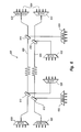
- FIG. 7 illustrates yet another system for increasing capacity over CWDM systems using DWDM devices according to one embodiment of the invention.
- FIG. 8 illustrates another system for increasing capacity over CWDM systems using DWDM devices according to one embodiment of the invention.
- optical fiber and “single fiber” are inclusive of other optical devices that may be interposed in a continuous optical path that commence and end with a single fiber.
- a “single fiber” may include a fiber stub that is attached at a first optical device, intermediate optical devices that sever the fiber, such as optical add drop multiplexers, yet nevertheless propagate at least some of the optical signals on the fiber, and a fiber stub that is attached to a second optical device.
- the recitation of a “single fiber” or an “optical fiber” between two nodes does not require the use of a single continuous fiber to span the entire distance between the nodes.
- FIG. 4 depicted is a conceptual graph showing that CWDM transmission may occur at one of eight wavelengths: typically 1470 nm, 1490 nm, 1510 nm, 1530 nm, 1550 nm, 1570 nm, 1590 nm, and 1610 nm.
- the channel spacing 402 between each of the adjacent channels is 20 nanometers and the bandwidth 404 of each of the channels is 12 nanometers.
- the present invention takes advantage of the cost-effective implementation of a CWDM system, while exhibiting the scalability available in DWDM systems.
- FIG. 4 shows DWDM channels mapped onto the bandwidth of CWDM channels.
- the individual channels have a channel spacing 502 of 20 nanometers.
- Each channel bandwidth 504 is 12 nanometers.
- a CWDM channel 410 is centered at 1550 nm with eight DWDM channels 408 superimposed thereon. As can be seen, because of the much narrower channel spacing of DWDM systems, a much greater number of DWDM channels can be added. Depending on the embodiment of DWDM implemented, various numbers of channels can be inserted and can occupy all or part of the CWDM channel. Thus, DWDM over CWDM is “scalable” in that desired scales of DWDM channels can be implemented as desired.
- CWDM components can be used in combination with DWDM components to effectively increase the bandwidth of the metro area network by a factor of eight in one particular embodiment. For example, while eight channels is the maximum number available in a CWDM network, by superimposing eight DWDM channels over the CWDM channels, 64 channels can be achieved.
- the DWDM over CWDM system 500 generally includes first and second CWDM multiplexer and demultiplexer pairs 502 , 504 at either end of a single fiber line 506 .
- a pair of coupling devices 508 , 510 (described in greater detail below) couple traffic from multiplexers 512 , 514 to line 506 and from line 506 to demultiplexers 516 , 518 .
- the depicted CWDM system can carry four or eight coarse wavelength channels in either direction over single line 506 , depending on the implementation of coupling devices 508 , 510 .
- the DWDM systems are generally inserted by first reserving one (or more if desired) CWDM channels for use by the DWDM modules.
- each C band filter pair 520 , 522 are placed on line 506 as desired, depending on the desired endpoints of the DWDM channel transmission.
- the passband filters may be either active passband filters that may require an external source of power for tunability and temperature stability or passive passband filters, requiring no external source of power and consisting only of passive components such as capacitors and inductors. If the CWDM 1550 channel is disabled, for example, each C band filter pair may include a C 1 passband filter specific to the 1538 nm to 1548 nm range and a C 2 passband filter specific to the 1552 nm to 1562 nm range.
- a first multiplexer 524 at one end of the line can then generate (together with the necessary transceivers) a first multiplexed signal over the C 1 passband, for example to travel one direction down line 506 .
- This first multiplexed signal is diverted at the far end of line 506 by one of the passband filters 522 to demultiplexer 526 .
- multiplexer 528 generates (together with the necessary transceivers) a second multiplexed signal over the C 2 passband, to travel the opposite direction down line 506 .
- This second multiplexed signal is in turn diverted at the far end of line 506 by one of the passband filters 520 to demultiplexer 530 .
- This DWDM over CWDM implementation is transparent to the regular CWDM traffic in that it occupies a channel spacing in the CWDM that was reserved for the DWDM. It is movable in that the entire DWDM system can be quickly and removably attached to a CWDM system via cables attached to the CWDM system at selected locations, along with the passband filters.
- the system is also scalable in that the reserved CWDM channel can be filled as desired depending on the capacity needs. For example, four, eight, or twelve DWDM channels can be fit within a single CWDM channel.
- Examples of coupling devices 508 , 510 include interleavers, passband filters, and circulators.
- An interleaver is a device used to combine odd and even numbered wavelengths from separate fibers into a single fiber.
- a multiplexer 512 can receives four odd numbered optical signals, ⁇ 1 , ⁇ 3 , ⁇ 5 , ⁇ 7 , from transceivers (not depicted) and couple the four signals, ⁇ 1 , ⁇ 3 , ⁇ 5 , ⁇ 7 , into a first multiplexed signal that is then communicated to the interleaver.
- the interleaver couples the first multiplexed signal onto line 506 .
- the interleaver also receives a second multiplexed signal from line 506 .
- the second multiplexed signal contains signals over the even numbered wavelengths ⁇ 2 , ⁇ 4 , ⁇ 6 , ⁇ 8 .
- This second multiplexed signal is coupled to demultiplexer 516 , which divides the multiplexed signal into its component signals over wavelengths ⁇ 2 , ⁇ 4 , ⁇ 6 , and ⁇ 8 and then couples each of the signals to an appropriate.
- the interleaver passively couples unidirectional signals over two fibers to and from a single bi-directional fiber without mixing the signals. This enables the use of a single fiber for optical communication between business campuses, over LANs, MANs, LANs, and other networks rather than the conventional dual fibers that are used for the same purpose.
- a passband filter also couples unidirectional signals over two fibers to and from a single BiDi fiber without mixing the signals.
- a passband filter operates by allowing signals between two specific wavelength frequencies to pass, but discriminates against signals at other wavelength frequencies.
- Such a passband filter may be either an active passband filter and require an external source of power and employ active components such as transistors and integrated circuits or be a passive passband filter, requiring no external source of power and consisting only of passive components such as capacitors and inductors.
- a multiplexer 512 can multiplex four signals, ⁇ 1 , ⁇ 2 , ⁇ 3 , ⁇ 4 , into a first multiplexed signal and then communicate the multiplexed signal to the passband filter, which in couples the first multiplexed signal onto line 506 .
- the passband filter also receives a second multiplexed signal from line 506 .
- the second multiplexed signal contains signals over a second range of wavelength frequencies ⁇ 5 , ⁇ 6 , ⁇ 7 , ⁇ 8 . This second multiplexes signal is coupled to demultiplexer 516 .
- Demultiplexer 516 divides the multiplexed signal into its component signals over wavelengths ⁇ 5 , ⁇ 6 , ⁇ 7 , ⁇ 8 and then couples each of the signals to an appropriate transceiver.
- the passband filter passively or actively couples unidirectional signals over two fibers to and from a single line 506 without mixing the signals.
- a circulator also couples unidirectional signals over two fibers to and from a single line 506 without mixing the signals.
- a circulator is generally a passive device having three ports that couples light from port 1 to port 2 and from port 2 to port 3 while having high isolation in the other directions. In the described example the circulator does even-odd separation, although various forms of separation are possible.
- multiplexer 512 receives four optical signals, ⁇ 1 , ⁇ 3 , ⁇ 5 , ⁇ 7 , from four transceivers and couples the four signals, ⁇ 1 , ⁇ 3 , ⁇ 5 , ⁇ 7 , into a first multiplexed signal which is then communicated to the circulator.
- the circulator in turn couples the first multiplexed signal onto line 506 while having high isolation in the other directions.
- the circulator also receives a second multiplexed signal, containing signals over a second range of wavelength frequencies ⁇ 2 , ⁇ 4 , ⁇ 6 , ⁇ 8 , from line 506 .
- This second multiplexed signal is coupled to demultiplexer 516 with a high degree of isolation in the other directions.
- Demultiplexer 516 divides the multiplexed signal into its component signals over wavelengths frequencies ⁇ 2 , ⁇ 4 , ⁇ 6 , ⁇ 8 and then couples each of the signals to one of various transceivers.
- the circulator passively couples unidirectional signals over two fibers to and from a single line 506 without mixing the signals.
- Circulators can also be used to double the per fiber capacity in BiDi systems. For example, in CWDM systems, instead of four channels per direction, eight channels per direction can be facilitated. This is performed by having a pair of circulators (e.g. coupling devices 508 , 510 ) at either end of a single fiber (e.g. line 506 ) used for CWDM BiDi data transmission.
- the first circulator couples a first eight channel CWDM optical signal from multiplexer 512 to line 506 with high isolation in the other directions.
- the second circulator couples a second optical signal from multiplexer 514 to line 506 with high isolation in the other directions.
- the first circulator also receives and couples the second optical signal from line 506 to demultiplexer 516 with high isolation in the other directions. Finally, the second circulator couples the first optical signal from line 506 to demultiplexer 518 with high isolation in the other directions.
- circulators according to his embodiment enable the passage of the same wavelength channels in each direction. In this manner, circulators enable the use of BiDi transmission over a single fiber without sacrificing the number of channels.
- An APC connector is a style of fiber optic connector with a 5°-15° angle on the connector tip for the minimum possible backreflection.
- Optical add drop multiplexers (“OADMs”) 550 , 552 , 554 , 556 can be inserted along line 506 as communications nodes.
- OADMs may include four port devices: with one port at each connection point to the main line for receiving and propagating the signal and two ports for connecting to transceivers for receiving data from the main line and adding data to the main line.
- the OADMs enable individual devices to connect to the line and access a single channel from the multiplexed signal on the line.
- OADMs are used at nodes, or connection points, to manage exchanges of data channel signals in an optical network.
- an add/drop module may drop an unused channel of a multiplexed signal while simultaneously adding a different, appropriate channel.
- OADMs may interface directly with a computer to communicate Ethernet data from a fiber-optic network, in which case the OADMs are used to extract the channel of interest from the multiplexed optical signal.
- OADMs also may be employed in transceivers or some other nodes in a fiber optic network.
- OADMs extract from the multiplexed signal those channels that are to be used by a device in the network. This enables components on a network, such as two computers, to communicate over the same wavelength, or channel, of a fiber optic signal, without necessarily interrupting bandwidth dedicated to the other channels in the signal.
- the add/drop module also can be used to insert the dropped channel back into the optical signal, or to include different data that is encoded on the same wavelength as the dropped channel.
- FIG. 6 depicted is a dual line CWDM system having DWDM modules inserted therein.
- This embodiment is substantially similar to the embodiment of FIG. 5 , with the main differences being that two lines are used and no coupling devices are used so each line has unidirectional traffic, not bi-directional traffic.
- the DWDM over CWDM system 600 generally includes first and second CWDM multiplexer and demultiplexer pairs 602 , 604 at either end of lines 606 , 608 .
- the depicted CWDM system can carry up to eight coarse wavelength channels in either direction over lines 606 , 608 .
- the passband filters may be either be active passband filters and require an external source of power and employ active components such as transistors and integrated circuits or be passive passband filters, requiring no external source of power and consisting only of passive components such as capacitors and inductors.
- a C band filter pair at each end of dual lines 606 , 608 may include a C 1 passband filter specific to the 1538 nm to 1548 nm range and a C 2 passband filter specific to the 1552 nm to 1562 nm range.
- a first DWDM multiplexer 626 can then generate (together with the necessary transceivers) a first multiplexed signal over the C 1 passband, for example to be directed one direction down line 606 by C 1 passband 610 . This first multiplexed signal is diverted at the far end of line 606 by C 1 passband filter 614 to DWDM demultiplexer 628 .
- DWDM multiplexer 632 generates (together with the necessary transceivers) a second multiplexed signal over the C 2 passband, to travel the opposite direction down lines 608 .
- This second multiplexed signal is in turn diverted at the far end of line 608 by a C 2 passband filter 612 to DWDM demultiplexer 630 .
- This DWDM over CWDM implementation is transparent to the regular CWDM traffic in that it occupies a channel spacing in the CWDM that was reserved for the DWDM. It is movable in that the entire DWDM system can be quickly and removably attached to a CWDM system via cables attached to the CWDM system at selected locations, along with the passband filters.
- the system is also scalable in that the reserved CWDM channel can be filled as desired depending on the capacity needs. For example, four, eight, or twelve channels can be fit within a single CWDM channel.
- OADMs as described above with respect to FIG. 5 can be inserted along lines 606 , 608 as communications nodes as desired.
- FIG. 7 A first exemplary configuration for implementing DWDM on a CWDM ring network is shown in FIG. 7 , and designated generally as 700 .
- the network 700 has a series of nodes 702 , 704 , 706 , 708 , 710 for example office buildings in a metro area network that are connected by a fiber optic ring.
- Each of the nodes 702 , 704 , 706 has an OADM 752 , 756 , 758 that is designed for a specific CWDM channel or optical wavelength.
- the CWDM network has capacity for four CWDM channels, not each of the channels is used so that DWDM channels can be inserted into the channels and increase network bandwidth.
- DWDM components are added to the network at various points. More particularly, the CWDM components at the 1550 and 1610 nodes 708 , 710 have been replaced by DWDM components.
- the 1550 and 1610 channels are selected for convenience in this embodiment because low cost Erbium-Doped Fiber Amplifier (EDFA) amplifiers are available for these channels.
- EDFA Erbium-Doped Fiber Amplifier
- the addition of these components allows the network to transmit and receive DWDM signals superimposed over the bandwidth of CWDM channels.
- OADMs 750 , 754 extract any wavelength of light within a selected bandwidth.
- DWDM mux/demuxes 716 , 718 , 720 , 722 are used to further divide the superimposed DWDM channels into their constituent parts so that the individual DWDM channels may be routed to DWDM GBIC transceivers.
- the GBIC transceivers return data to the network through the DWDM mux/demuxes that multiplex the signals and return them to the network.
- DWDM mux/demuxes can be used at each of the nodes in the CWDM network as desired to greatly increase bandwidth, as depicted in FIG. 7 .
- demultiplexers 760 , 761 , 770 and muxes 762 , 764 , 768 are inserted at nodes 702 , 704 , 706 to insert the DWDM channels at OADMs 752 , 756 , 758 .
- FIG. 8 the transparent insertion of DWDM OADMs over a CWDM network 800 is depicted.
- FIG. 7 illustrates the replacement of CWDM components with DWDM components in selected locations
- the embodiment of FIG. 8 leaves the CWDM OADMs in place.
- mux/demux module pairs 802 can effect data transmission over selected DWDM channels that fall within one or more CWDM channels that are reserved on network 800 .
- These DWDM channels pass transparently through CWDM OADMs 804 , 806 , 808 , 810 , 812 on the reserved CWDM channel.
- pluggable DWDM transceivers By using pluggable DWDM transceivers, network designers can build low-cost CWDM networks and then scale the bandwidth with DWDM technology as the network grows. For example, using a 100 GHz DWDM pluggable transceiver, the network can be scaled to 64 wavelengths when using an eight wavelength CWDM system. Using a 50 GHz transceiver, 128 wavelengths can be implemented on the CWDM network. Using a 25 GHz transceiver, the network can be scaled to 256 wavelengths.
Landscapes
- Engineering & Computer Science (AREA)
- Computer Networks & Wireless Communication (AREA)
- Signal Processing (AREA)
- Optical Communication System (AREA)
Abstract
Description
Claims (12)
Priority Applications (1)
| Application Number | Priority Date | Filing Date | Title |
|---|---|---|---|
| US10/889,333 US7805077B2 (en) | 2003-07-11 | 2004-07-12 | Scalable and movable DWDM usage of CWDM networks |
Applications Claiming Priority (3)
| Application Number | Priority Date | Filing Date | Title |
|---|---|---|---|
| US48677003P | 2003-07-11 | 2003-07-11 | |
| US49324203P | 2003-08-07 | 2003-08-07 | |
| US10/889,333 US7805077B2 (en) | 2003-07-11 | 2004-07-12 | Scalable and movable DWDM usage of CWDM networks |
Publications (2)
| Publication Number | Publication Date |
|---|---|
| US20050025488A1 US20050025488A1 (en) | 2005-02-03 |
| US7805077B2 true US7805077B2 (en) | 2010-09-28 |
Family
ID=34108826
Family Applications (1)
| Application Number | Title | Priority Date | Filing Date |
|---|---|---|---|
| US10/889,333 Active 2028-04-19 US7805077B2 (en) | 2003-07-11 | 2004-07-12 | Scalable and movable DWDM usage of CWDM networks |
Country Status (1)
| Country | Link |
|---|---|
| US (1) | US7805077B2 (en) |
Cited By (1)
| Publication number | Priority date | Publication date | Assignee | Title |
|---|---|---|---|---|
| US20150304036A1 (en) * | 2014-04-17 | 2015-10-22 | Nec Laboratories America, Inc. | Interleaved Bidirectional Sub-Nyquist Transmission with Overlapping Counter-Propagating Signal Spectral Bands |
Families Citing this family (14)
| Publication number | Priority date | Publication date | Assignee | Title |
|---|---|---|---|---|
| KR100606051B1 (en) * | 2004-09-24 | 2006-07-28 | 삼성전자주식회사 | Bidirectional optical branching / combining multiplexer and bidirectional wavelength division multiplexing annular network |
| CA2591988A1 (en) * | 2004-12-20 | 2006-06-29 | Xtend Networks Ltd. | System, device and method of expanding the operational bandwidth of a communication infrastructure |
| US7463832B2 (en) * | 2005-08-09 | 2008-12-09 | The Boeing Company | Thermal drift compensation system and method for optical networks |
| US20070280688A1 (en) * | 2006-04-21 | 2007-12-06 | Matisse Networks | Upgradeable optical hub and hub upgrade |
| US8417117B2 (en) * | 2006-10-10 | 2013-04-09 | Alcatel Lucent | DWDM and CWDM hybrid PON system and method |
| EP2182659B1 (en) * | 2008-10-30 | 2019-04-17 | ADTRAN GmbH | Method and optical system for the transmission of signals |
| KR20140110736A (en) * | 2013-03-08 | 2014-09-17 | 에릭슨 엘지 주식회사 | Signal processing method and bidirectional coarse wavelength division multiplexing ring network system for the same |
| ES2530888B2 (en) * | 2013-09-06 | 2015-10-08 | Universidad Politécnica de Madrid | PASSIVE OPTICAL MULTIPLEXOR |
| CN105227242A (en) * | 2014-06-17 | 2016-01-06 | 中兴通讯股份有限公司 | Opto-electronic receiver, launching technique, device, optoelectronic transceiver method, module, equipment |
| US12015444B2 (en) * | 2015-07-13 | 2024-06-18 | Novec Solutions, Inc. | System, apparatus and method for two-way transport of data over a single fiber strand |
| CN108028705B (en) * | 2015-07-13 | 2021-09-03 | 北弗吉尼亚电力合作社 | System, apparatus and method for bidirectional transmission of data over a single fiber bundle |
| CN112769519A (en) * | 2019-11-04 | 2021-05-07 | 中国电信股份有限公司 | Optical signal communication system |
| CN113193918B (en) * | 2021-04-26 | 2022-08-09 | 上海交通大学 | Apparatus for combining time and frequency transfer signals into a single 100G wavelength division multiplexed channel transmission |
| US12328182B2 (en) * | 2022-03-04 | 2025-06-10 | Hewlett Packard Enterprise Development Lp | Optical devices for coarse wavelength division multiplexing wavebands |
Citations (12)
| Publication number | Priority date | Publication date | Assignee | Title |
|---|---|---|---|---|
| US5864413A (en) * | 1996-02-23 | 1999-01-26 | Lucent Technologies, Inc. | Passive optical network for dense WDM downstream data transmission and upstream data transmission |
| US20010026385A1 (en) * | 1999-09-23 | 2001-10-04 | Cao Simon X.F. | Optical performance monitor |
| US20020041413A1 (en) * | 2000-06-29 | 2002-04-11 | Daniel Wang | Method for wavelength switch network restoration |
| US20020105692A1 (en) * | 2001-02-07 | 2002-08-08 | Richard Lauder | Hierarchical WDM in client-server architecture |
| US20020110314A1 (en) * | 2001-02-12 | 2002-08-15 | Connolly Matthew W. | System and method for narrow channel spaced dense wavelength division multiplexing/demultiplexing |
| US20020118417A1 (en) * | 2001-02-05 | 2002-08-29 | Barry Richard A. | Flexible optical add/drop architecture |
| US20020196491A1 (en) * | 2001-06-25 | 2002-12-26 | Deng Kung Li | Passive optical network employing coarse wavelength division multiplexing and related methods |
| US20030076560A1 (en) * | 2001-07-20 | 2003-04-24 | Pratt Michael K. | Single fiber passive optical network wavelength division multiplex overlay |
| US20030180045A1 (en) * | 2002-03-22 | 2003-09-25 | Nec Corporation | System and method for optical transmission |
| US20050025486A1 (en) * | 2003-08-01 | 2005-02-03 | Johnny Zhong | Bi-directional wavelength division multiplexing module |
| US20050084262A1 (en) * | 2001-12-18 | 2005-04-21 | Magnus Oberg | Protected bidirectional wdm network |
| US6973268B1 (en) * | 2000-06-30 | 2005-12-06 | Lucent Technologies Inc. | Bi-directional optical transmission using dual channel bands |
-
2004
- 2004-07-12 US US10/889,333 patent/US7805077B2/en active Active
Patent Citations (13)
| Publication number | Priority date | Publication date | Assignee | Title |
|---|---|---|---|---|
| US5864413A (en) * | 1996-02-23 | 1999-01-26 | Lucent Technologies, Inc. | Passive optical network for dense WDM downstream data transmission and upstream data transmission |
| US20010026385A1 (en) * | 1999-09-23 | 2001-10-04 | Cao Simon X.F. | Optical performance monitor |
| US20020041413A1 (en) * | 2000-06-29 | 2002-04-11 | Daniel Wang | Method for wavelength switch network restoration |
| US6973268B1 (en) * | 2000-06-30 | 2005-12-06 | Lucent Technologies Inc. | Bi-directional optical transmission using dual channel bands |
| US20020118417A1 (en) * | 2001-02-05 | 2002-08-29 | Barry Richard A. | Flexible optical add/drop architecture |
| US20020105692A1 (en) * | 2001-02-07 | 2002-08-08 | Richard Lauder | Hierarchical WDM in client-server architecture |
| US20020110314A1 (en) * | 2001-02-12 | 2002-08-15 | Connolly Matthew W. | System and method for narrow channel spaced dense wavelength division multiplexing/demultiplexing |
| US20020196491A1 (en) * | 2001-06-25 | 2002-12-26 | Deng Kung Li | Passive optical network employing coarse wavelength division multiplexing and related methods |
| US20030076560A1 (en) * | 2001-07-20 | 2003-04-24 | Pratt Michael K. | Single fiber passive optical network wavelength division multiplex overlay |
| US7254330B2 (en) * | 2001-07-20 | 2007-08-07 | Tellabs Bedford, Inc. | Single fiber passive optical network wavelength division multiplex overlay |
| US20050084262A1 (en) * | 2001-12-18 | 2005-04-21 | Magnus Oberg | Protected bidirectional wdm network |
| US20030180045A1 (en) * | 2002-03-22 | 2003-09-25 | Nec Corporation | System and method for optical transmission |
| US20050025486A1 (en) * | 2003-08-01 | 2005-02-03 | Johnny Zhong | Bi-directional wavelength division multiplexing module |
Non-Patent Citations (5)
| Title |
|---|
| Aldridge, J., The Best of Both Worlds, [online] Sep. 2002 [retrieved on Oct. 23, 2002]. Retrieved from the Internet: URL:http://lwe.pennnet.com/Articles/Article-Display.cfm?Section=Articles&Subsection=Display&ARTICLE-ID=155526. |
| Bell, Robert, World Teleport Association, Intelligent Cities and Tech-Space: What Lies Ahead [online] Feb. 2002, [retrieved on Nov. 7, 2002]. Retrieved from the Internet: URL:http://www.facilitycity.com/busfac/bf-02-02-intel.asp. |
| U.S. Appl. No. 10/802,434, filed Mar. 17, 2004, James Finn Aldridge. |
| U.S. Appl. No. 10/910,184, filed Aug. 2, 2004, James Finn Aldridge, et al. |
| U.S. Appl. No. 10/910,424, filed Aug. 2, 2004, Johnny Zhong, et al. |
Cited By (1)
| Publication number | Priority date | Publication date | Assignee | Title |
|---|---|---|---|---|
| US20150304036A1 (en) * | 2014-04-17 | 2015-10-22 | Nec Laboratories America, Inc. | Interleaved Bidirectional Sub-Nyquist Transmission with Overlapping Counter-Propagating Signal Spectral Bands |
Also Published As
| Publication number | Publication date |
|---|---|
| US20050025488A1 (en) | 2005-02-03 |
Similar Documents
| Publication | Publication Date | Title |
|---|---|---|
| US20050025486A1 (en) | Bi-directional wavelength division multiplexing module | |
| US6256431B1 (en) | WDM multiplexer | |
| US6810215B1 (en) | Optical repeater converting wavelength and bit rate between networks | |
| US7805077B2 (en) | Scalable and movable DWDM usage of CWDM networks | |
| EP2665212A1 (en) | Optical data transmission system | |
| US20090047019A1 (en) | Method and System for Communicating Optical Traffic | |
| KR20040005841A (en) | WDM Optical Communication System With Channels Supporting Multiple Data Formats | |
| US6348984B1 (en) | Optical add/drop multiplexer | |
| US6512864B1 (en) | Optical multiplexer/demultiplexer arrangement for WDM signals having in-band and out-of-band signal components | |
| GB2352104A (en) | Upgrading from a single wavelength to a multi-wavelength optical communications system | |
| US20060239609A1 (en) | Methods and apparatuses to increase wavelength channels in a wavelength-division-multiplexing passive-optical-network | |
| CN1473409A (en) | Bidirectional WDM optical communication network with optical bridges between bidirectional optical waveguides | |
| US6400478B1 (en) | Wavelength-division-multiplexed optical transmission system with expanded bidirectional transmission capacity over a single fiber | |
| WO2000008791A1 (en) | Wdm optical communication system having reduced loss and cross-talk | |
| KR20030070903A (en) | Bidirectional wdm optical communication network with data bridging plural optical channels between bidirectional optical waveguides | |
| US7457543B2 (en) | Add/drop module for single fiber wavelength division multiplexing systems | |
| US7085447B2 (en) | System for optically demultiplexing wavelength bands | |
| CN105144615A (en) | Increasing the capacity of a wdm-pon with wavelength reuse | |
| US20020118417A1 (en) | Flexible optical add/drop architecture | |
| US9800342B2 (en) | Optical WDM transmission network | |
| EP1407567B1 (en) | Optical filtering by using an add-drop node | |
| US6493118B1 (en) | Add/drop capability for ultra-high speed dense wavelength division multiplexed systems using a wavelength bus architecture | |
| US7389017B2 (en) | Dense wavelength division multiplexing on coarse wavelength division multiplexing networks | |
| US20050129403A1 (en) | Method and system for communicating optical traffic at a node | |
| JP2001218240A (en) | Optical system |
Legal Events
| Date | Code | Title | Description |
|---|---|---|---|
| AS | Assignment |
Owner name: FINISAR CORPORATION, CALIFORNIA Free format text: ASSIGNMENT OF ASSIGNORS INTEREST;ASSIGNORS:WANG, STEVE;ZHONG, JOHNNY;ALDRIDGE, JAMES FINN;REEL/FRAME:015559/0954;SIGNING DATES FROM 20040721 TO 20041014 Owner name: FINISAR CORPORATION, CALIFORNIA Free format text: ASSIGNMENT OF ASSIGNORS INTEREST;ASSIGNORS:WANG, STEVE;ZHONG, JOHNNY;ALDRIDGE, JAMES FINN;SIGNING DATES FROM 20040721 TO 20041014;REEL/FRAME:015559/0954 |
|
| STCF | Information on status: patent grant |
Free format text: PATENTED CASE |
|
| FPAY | Fee payment |
Year of fee payment: 4 |
|
| MAFP | Maintenance fee payment |
Free format text: PAYMENT OF MAINTENANCE FEE, 8TH YEAR, LARGE ENTITY (ORIGINAL EVENT CODE: M1552) Year of fee payment: 8 |
|
| AS | Assignment |
Owner name: BANK OF AMERICA, N.A., AS ADMINISTRATIVE AGENT, NO Free format text: NOTICE OF GRANT OF SECURITY INTEREST IN PATENTS;ASSIGNORS:II-VI INCORPORATED;MARLOW INDUSTRIES, INC.;EPIWORKS, INC.;AND OTHERS;REEL/FRAME:050484/0204 Effective date: 20190924 Owner name: BANK OF AMERICA, N.A., AS ADMINISTRATIVE AGENT, NORTH CAROLINA Free format text: NOTICE OF GRANT OF SECURITY INTEREST IN PATENTS;ASSIGNORS:II-VI INCORPORATED;MARLOW INDUSTRIES, INC.;EPIWORKS, INC.;AND OTHERS;REEL/FRAME:050484/0204 Effective date: 20190924 |
|
| AS | Assignment |
Owner name: II-VI DELAWARE, INC., DELAWARE Free format text: ASSIGNMENT OF ASSIGNORS INTEREST;ASSIGNOR:FINISAR CORPORATION;REEL/FRAME:052286/0001 Effective date: 20190924 |
|
| MAFP | Maintenance fee payment |
Free format text: PAYMENT OF MAINTENANCE FEE, 12TH YEAR, LARGE ENTITY (ORIGINAL EVENT CODE: M1553); ENTITY STATUS OF PATENT OWNER: LARGE ENTITY Year of fee payment: 12 |
|
| AS | Assignment |
Owner name: JPMORGAN CHASE BANK, N.A., AS COLLATERAL AGENT, NEW YORK Free format text: SECURITY INTEREST;ASSIGNORS:II-VI INCORPORATED;II-VI DELAWARE, INC.;M CUBED TECHNOLOGIES, INC.;AND OTHERS;REEL/FRAME:060562/0254 Effective date: 20220701 |
|
| AS | Assignment |
Owner name: PHOTOP TECHNOLOGIES, INC., CALIFORNIA Free format text: PATENT RELEASE AND REASSIGNMENT;ASSIGNOR:BANK OF AMERICA, N.A., AS ADMINISTRATIVE AGENT;REEL/FRAME:060574/0001 Effective date: 20220701 Owner name: II-VI OPTOELECTRONIC DEVICES, INC., NEW JERSEY Free format text: PATENT RELEASE AND REASSIGNMENT;ASSIGNOR:BANK OF AMERICA, N.A., AS ADMINISTRATIVE AGENT;REEL/FRAME:060574/0001 Effective date: 20220701 Owner name: II-VI DELAWARE, INC., PENNSYLVANIA Free format text: PATENT RELEASE AND REASSIGNMENT;ASSIGNOR:BANK OF AMERICA, N.A., AS ADMINISTRATIVE AGENT;REEL/FRAME:060574/0001 Effective date: 20220701 Owner name: II-VI PHOTONICS (US), INC., MASSACHUSETTS Free format text: PATENT RELEASE AND REASSIGNMENT;ASSIGNOR:BANK OF AMERICA, N.A., AS ADMINISTRATIVE AGENT;REEL/FRAME:060574/0001 Effective date: 20220701 Owner name: M CUBED TECHNOLOGIES, INC., CONNECTICUT Free format text: PATENT RELEASE AND REASSIGNMENT;ASSIGNOR:BANK OF AMERICA, N.A., AS ADMINISTRATIVE AGENT;REEL/FRAME:060574/0001 Effective date: 20220701 Owner name: II-VI OPTICAL SYSTEMS, INC., CALIFORNIA Free format text: PATENT RELEASE AND REASSIGNMENT;ASSIGNOR:BANK OF AMERICA, N.A., AS ADMINISTRATIVE AGENT;REEL/FRAME:060574/0001 Effective date: 20220701 Owner name: FINISAR CORPORATION, CALIFORNIA Free format text: PATENT RELEASE AND REASSIGNMENT;ASSIGNOR:BANK OF AMERICA, N.A., AS ADMINISTRATIVE AGENT;REEL/FRAME:060574/0001 Effective date: 20220701 Owner name: OPTIUM CORPORATION, CALIFORNIA Free format text: PATENT RELEASE AND REASSIGNMENT;ASSIGNOR:BANK OF AMERICA, N.A., AS ADMINISTRATIVE AGENT;REEL/FRAME:060574/0001 Effective date: 20220701 Owner name: COADNA PHOTONICS, INC., PENNSYLVANIA Free format text: PATENT RELEASE AND REASSIGNMENT;ASSIGNOR:BANK OF AMERICA, N.A., AS ADMINISTRATIVE AGENT;REEL/FRAME:060574/0001 Effective date: 20220701 Owner name: KAILIGHT PHOTONICS, INC., CALIFORNIA Free format text: PATENT RELEASE AND REASSIGNMENT;ASSIGNOR:BANK OF AMERICA, N.A., AS ADMINISTRATIVE AGENT;REEL/FRAME:060574/0001 Effective date: 20220701 Owner name: LIGHTSMYTH TECHNOLOGIES, INC., OREGON Free format text: PATENT RELEASE AND REASSIGNMENT;ASSIGNOR:BANK OF AMERICA, N.A., AS ADMINISTRATIVE AGENT;REEL/FRAME:060574/0001 Effective date: 20220701 Owner name: EPIWORKS, INC., ILLINOIS Free format text: PATENT RELEASE AND REASSIGNMENT;ASSIGNOR:BANK OF AMERICA, N.A., AS ADMINISTRATIVE AGENT;REEL/FRAME:060574/0001 Effective date: 20220701 Owner name: MARLOW INDUSTRIES, INC., TEXAS Free format text: PATENT RELEASE AND REASSIGNMENT;ASSIGNOR:BANK OF AMERICA, N.A., AS ADMINISTRATIVE AGENT;REEL/FRAME:060574/0001 Effective date: 20220701 Owner name: II-VI INCORPORATED, PENNSYLVANIA Free format text: PATENT RELEASE AND REASSIGNMENT;ASSIGNOR:BANK OF AMERICA, N.A., AS ADMINISTRATIVE AGENT;REEL/FRAME:060574/0001 Effective date: 20220701 |