US7804518B2 - Enhanced underwater imaging - Google Patents
Enhanced underwater imaging Download PDFInfo
- Publication number
- US7804518B2 US7804518B2 US10/588,127 US58812705A US7804518B2 US 7804518 B2 US7804518 B2 US 7804518B2 US 58812705 A US58812705 A US 58812705A US 7804518 B2 US7804518 B2 US 7804518B2
- Authority
- US
- United States
- Prior art keywords
- image
- scene
- underwater
- imaging device
- imaging
- Prior art date
- Legal status (The legal status is an assumption and is not a legal conclusion. Google has not performed a legal analysis and makes no representation as to the accuracy of the status listed.)
- Expired - Fee Related
Links
Images


Classifications
-
- G—PHYSICS
- G06—COMPUTING OR CALCULATING; COUNTING
- G06T—IMAGE DATA PROCESSING OR GENERATION, IN GENERAL
- G06T5/00—Image enhancement or restoration
- G06T5/90—Dynamic range modification of images or parts thereof
-
- G—PHYSICS
- G06—COMPUTING OR CALCULATING; COUNTING
- G06T—IMAGE DATA PROCESSING OR GENERATION, IN GENERAL
- G06T5/00—Image enhancement or restoration
- G06T5/73—Deblurring; Sharpening
-
- H—ELECTRICITY
- H04—ELECTRIC COMMUNICATION TECHNIQUE
- H04N—PICTORIAL COMMUNICATION, e.g. TELEVISION
- H04N23/00—Cameras or camera modules comprising electronic image sensors; Control thereof
- H04N23/50—Constructional details
- H04N23/55—Optical parts specially adapted for electronic image sensors; Mounting thereof
Definitions
- the present invention relates to imaging. More particularly, the present invention relates to enhanced underwater imaging.
- Underwater vision is plagued by poor visibility conditions. Direct employment of most computer vision methods (e.g., those based on stereo triangulation or on structure from motion) underwater is difficult. This is due to the particularly challenging environmental conditions, which complicate image matching and analysis. It is important to alleviate these visibility problems, since underwater imaging is widely used in scientific research and technology. Computer vision methods are being used in this mode of imaging for various applications (see, for example, A. Ortiz, M. Simo, and G. Oliver, “A vision system for an underwater cable tracker,” in Machine Vision and Applications, vol. 13, pp. 129-140, 2002) such as mine detection, inspection of underwater power and telecommunication cables, pipelines, nuclear reactors, and columns of offshore platforms.
- Underwater computer vision is also used commercially to help swimming pool life-guards. As in conventional computer vision, algorithms are sought for navigation and control of submerged robots. In addition, underwater imaging is used for research in marine biology, archaeology and mapping. Moreover, underwater photography is becoming more accessible to the wider public.
- DOP degree of polarization
- a method for enhancing underwater imaging affected by image degradation effects comprising:
- the image characteristics comprise at least one of the characteristics group consisting of: contrast, color, sharpness, brightness.
- compensating effects attributed to the underwater depth of the scene comprises white-balancing.
- the physics-based mathematical model comprises an inversion of an image-formation model including backscatter.
- acquiring of at least one image of the underwater scene comprises acquiring at least two images in different imaging conditions.
- said at least two images are acquired in different resolution.
- acquiring at least two images in different imaging conditions comprises acquiring at least two images of the scene in different polarizing states on the imaging device.
- acquiring said at least two images comprises acquiring said at least two images simultaneously.
- the reconstructed image comprises three-dimensional rendering of the scene.
- the information regarding distances of parts of the scene relative to the imaging device is used to reconstruct a distance map of the scene.
- the imaging device comprises a camera.
- the imaging device comprises at least two cameras.
- determining of information regarding distances of parts of the scene relative to the imaging device comprises extracting the information from said at least one image.
- a system for enhancing underwater imaging affected by image degradation effects comprising:
- FIG. 1 illustrates imaging characteristics of an underwater scene.
- FIG. 2 is a plot showing numerical assessment of the correction coefficient as a function of focal length and attenuation coefficient.
- FIG. 3 a and FIG. 3 b depict scattering of light towards the Line of Sight (LOS) by particles close the LOS.
- LOS Line of Sight
- FIG. 4 illustrates imaging characteristics of an underwater scene through a polarizing filter.
- FIG. 5 plots the reflectance of glass in water, divided by this reflectance in air.
- FIG. 6 a illustrates an undesired effect, photoelasticity of the window of the imaging device that affects polarization.
- FIG. 6 b illustrates placement of a polarizer externally to the imaging device to minimize the effect shown in FIG. 6 a.
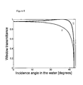
- FIG. 7 a illustrates an undesired effect: the transmittance of a flat window is polarization-dependent at oblique incidence.
- FIG. 7 b illustrates a spherical dome concentric with the center of projection that eliminates the effects shown in FIG. 7 a.
- FIG. 8 illustrates a plot showing the transmittance of polarization components, derived from Fresnel's equations.
- FIG. 9 illustrates an inverted circular polarizer.
- the intensity and color of each scene point essentially depend two unknown pointwise characteristics: the albedo of the object point and the distance to that point.
- the multiple acquisitions of the scene, say through the polarizing filter enables our algorithm to solve for the object intrinsic appearance as well as for the object distance. Note that in principle the method of the present invention may be applied to a single image taken, if the distances of different parts of the scene from the imaging device and illumination sources are known, are measured or are estimated.
- the first source is the scene object at distance z, whose radiance is attenuated by absorption and scattering in the water. It is also somewhat blurred. The image corresponding to this degraded source is the signal.
- the second source is the ambient illumination. Part of the ambient light is scattered towards the camera by the particles in the water, and is termed in the literature as veiling light, path radiance, space-light and backscatter. The veiling light is partially polarized. This fact is used in our preferred visibility restoration algorithm. We now describe each of these components.
- the signal is composed of two components, termed direct transmission and forward scattering.
- z is the distance to the object, which depends on the pixel coordinates x and y, while c is the attenuation coefficient.
- L object is the object radiance we would have sensed, had there been no scattering and absorption along the line of sight (LOS).
- the scattering coefficient b expresses the ability of an infinitesimal water volume to scatter flux in all directions. Integrating over all solid angles ⁇ right arrow over ( ⁇ ) ⁇
- ⁇ is the scattering angle relative to the propagation direction.
- the angular scattering coefficient b( ⁇ ) is sometimes referred to as the phase function. Note that the variables a, b( ⁇ ), c and L object are all functions of the wavelength ⁇ .
- the PSF is parameterized by the distance z, since the further the object, the wider the support of the blur kernel.
- Veiling light does not originate from the object on the LOS. Rather, light coming from illumination sources is scattered towards the camera ( FIG. 1 ). In particular, in natural illumination, the LOS is lit mostly from the water surface above. In addition, the LOS is illuminated by the sea bottom and by scattering particles in the surrounding water volume. Before integrating all the contributions, let us first analyze the effect of a single distant source on a horizontal LOS.
- the contribution of this source to the veiling light is (see B. L. McGlamery, “A computer model for underwater camera system,” in Proc. SPIE, vol. 208, pp. 221-231, 1979)
- B ⁇ ⁇ ⁇ ⁇ ⁇ r ⁇ ⁇ ⁇ B ⁇ ⁇ ⁇ ⁇ ( ⁇ r ⁇ ) approx ⁇ ⁇ d r ⁇ ( 14 ) is a scalar termed the water background, which depends on ⁇ .
- the veiling light B implicitly depends on x and y due to its explicit dependence on the distance z.
- FIG. 3 depicts scattering of light towards the LOS by particles close the LOS. It shows that this light can be represented as originating from equivalent sources at infinity.
- This equivalence is based on an assumption of homogeneous lighting along the LOS. We believe that this is a reasonable assumption in horizontal photography in natural illumination. The reason is that underwater lighting naturally comes from a limited light cone around the zenith, and is thus typically unobscured along the LOS. Thanks to this equivalence, expression (13), which was developed for distant light sources is applicable to the general case of scattering from non-distant particles suspended in the water volume.
- the contrast of the effective object C(L object effective ) and the sensed image C(I total ) are calculated. Relative to the contrast of the original scene, the degradation of contrast Is
- Underwater scattering involves polarization effects. We exploit these effects to compensate for underwater visibility degradation. Let us describe the models for these effects.
- a narrow source which illuminates the scattering particles residing on the LOS.
- the narrow source and the LOS from the camera to the object define a plane of incidence.
- the veiling light is partially polarized perpendicular to the plane.
- the illumination can be fully polarized, for example it can be fully linearly polarized or circularly polarized. The intentional polarization of the source enables an increased polarization of the veiling light.
- irradiance of the LOS is not due to a narrow source.
- the LOS is generally illuminated in a highly anisotropic manner.
- illumination originates from the sun and sky above the water. This light is restricted to cone around the zenith called the optical manhole or Snell's window. Scattering in the water leads to illumination of the LOS from other directions as well (e.g., from below and from the sides), but with lower intensity. Changes caused by this scattering to the angular irradiance distribution gradually depend of the underwater depth. As we go deeper under the water surface, the natural illumination reaches an asymptotic distribution, which is strongly peaked around the zenith.
- I max is the image taken at the “worst state” of the polarizer, where the disturbing veiling is maximal.
- I min is the image taken at the “best state” of the polarizer, where the disturbing veiling is minimal. For this reason, some past methods were based on simple acquisition of I min . However, in most cases, I min is still a highly degraded version of L object , where the degradation is spatially varying and is affected by the distance of the object from the camera and from the illumination source.
- the algorithm for improving underwater visibility overcomes the “veiling” effect caused by scattered light. For this reason, the adjective unveiled is used to describe the image resulting from the algorithm.
- the adjective unveiled is used to describe the image resulting from the algorithm.
- a longer path from the illuminant to the object results not only in loss of brightness, but also in a color bias.
- the reason is attenuation of the illumination is a function of spectral bands. For example, in natural illumination in the open sea, as we go deeper underwater, the red portion of the illumination spectrum is absorbed by the water faster than the green-blue band. Compensating for this color bias is thus a very important step, that makes this problem unique, relative to methods that attempt improvement of visibility in the atmosphere (where the illumination color bias is usually marginal).
- space-invariant enhancement methods do not model the spatially varying distance dependencies of visibility problems. As a result, they are of limited utility.
- a naive space-invariant enhancement let us consider a simplistic method for compensating the illumination blue color bias when photographing in natural lighting. Suppose we know that the sand in the diving site is rather white. If the scene does not include such a natural object, then a white target can be introduced to the scenery.
- I red modified I red raw /I sand — red raw
- I green modified I green raw /I sand — green raw I blue modified ⁇ I blue raw /I sand — blue raw
- This multiplicative normalization does not compensate for the additive spatially varying veiling light. For this reason, the measured color values of a white patch I sand — red raw , I sand — green raw and I sand — blue raw depend on the image coordinates x, y of the selected patch. Therefore, this compensation is ill defined.
- Eq. (28) is an estimate L object effective . Thus, it does not compensate for image blur, but only for the veiling effect of scattered light and for attenuation. If we wish, we can do make do with this estimate.
- veiling light is the prime reason for image contrast degradation, hence overcoming veiling light, rather than blur, is the prime step for recovering visibility.
- image “deblurring” can be performed (at the price of noise amplification).
- the distance-dependent blur kernel should be known. This may be done by the aid of the distance estimation described in the following.
- Eqs. (27-29) invert the spatially varying visibility degradation effects that are associated with the object's position relative to the camera. This enables proper compensation for the color bias of the illumination. Assume that the illumination is uniform. Again, we use a patch of the scene, which we know should be white, if it were not for the illumination color (typically blue).
- the result is scene recovery.
- the recovered image has a much improved contrast and color.
- ⁇ recovered ⁇ ⁇ 2 t ⁇ ⁇ 1 + 1 P 2 ⁇ ( 1 - L ⁇ object effective B ⁇ ) 2 ( 36 )
- the signal to noise ratio (SNR) decreases exponentially with the distance z. This is not a distinctive shortcoming of our polarization-based method. Rather, it is due to attenuation of the signal with the distance from the object, as is the case for other underwater imaging modalities. In methods based on artificial illumination, the SNR decreases even faster as a function of object distance. The reason is that the radiation is attenuated for approximately twice the object distance, beyond the 1/z 2 falloff of the artificial illumination incident on the object, caused by free space propagation. Eq. (37) indicates that for a given level of output noise, the visibility range is proportional to the number of reliable camera bits. Thus, information from a 12-bit camera can recover objects that are 50% farther than those recoverable from data taken by an 8-bit camera, if quantization is an effective indication for the overall noise.
- Noise can be reduced by spatial filtering, e.g., local averaging. Performing this directly on the raw images or on ⁇ circumflex over (L) ⁇ object effective (x,y) would result in image blur, however there is a way to bypass this problem.
- ⁇ circumflex over (B) ⁇ (x,y) and ⁇ circumflex over (t) ⁇ (x,y) do not vary rapidly across the FOV.
- the veiling light is typically a smooth function of spatial location, contrary to the rapid spatial variations of intensity and texture of the object L object .
- the value ⁇ circumflex over (p) ⁇ obtained from direct measurement of image pixels should be slightly modified, for two reasons. The first is to limit instability. The second reason is the need to minimize the instances of negative pixel values. Negative pixel values stem from inaccurate measurement of ⁇ circumflex over (p) ⁇ and ⁇ circumflex over (B) ⁇ ⁇ and due to image noise. From Eqs. (15, 27),
- Histogram equalization of the raw image may improve the parts of scene, but on the other hand decrease the image quality in other parts. Furthermore, because the histogram of an image depends on the objects in the scene, the histogram of a partial frame image is different than that of the whole frame, leading to inconsistent results. Moreover, histogram equalization of color images is ill defined, and therefore colors are generally distorted by this operation, rather than being recovered.
- the DOP and polarization difference imaging (PDI) methods are based on imaging through a polarizer.
- DOP and DPI use I max and I min differently than our method, and implicitly assume that polarization is associated with the signal rather than the veiling light, contrary to our method.
- these prior methods perform poorly, and do not recover the scenes at all, especially at long distances.
- a different equation was suggested to enhance underwater polarization images (see P. C. Y. Chang, J. C. Flitton, K. I. Hopcraft, E. Jakeman, D. L. Jordan, and J. G. Walker, “Improving visibility depth in passive underwater imaging by use of polarization,” Applied Optics, vol. 42, pp. 2794-2802, 2003). That method is formulated for grayscale images, using ad-hoc formulation that does not resemble inversion of the image degradation process. The results of this formation have been unsuccessful in our experiments.
- the recovered range map can be used to render the scene (recovered, raw or processed otherwise) from viewpoints other than the ones used during acquisition.
- the method is based on a simple analysis of one or more (in the example we used a pair on images from which information on the relative distances of different parts of the scene can be obtained (in the example we acquired this information through the use of a polarizing filter). Since it is physics-based, the method also recovers information about the scene structure (distances). The algorithm can exploits natural lighting.
- the experimental set up we used.
- the camera should preferably have a linear radiometric response, besides being of low noise.
- a polarizing filter can placed inside the housing, or outside. If the polarizer is inserted in the housing ( FIG. 6 a ), this could spatially vary the transmittance though the polarizer, depending on ⁇ and the polarization state, due to the photoelastic effect.
- the effect may vary with the underwater depth, due to changes in the external water pressures.
- placing the polarizer externally should eliminate visible photoelastic effects.
- the filter is the first optical component the light from the scene encounters as it enters the imaging system.
- the space between the external polarizer and the port is filled with the water coming from the surroundings.
- photoelastic visible effects are indeed greatly diminished.
- An additional step we took for minimizing this effect is to use a glass port.
- Typical ports for underwater photography are either of dome shape, or flat.
- FIG. 7 a and FIG. 7 b The chief ray from an object point in the water to the detector undergoes an angular deviation at flat window interfaces.
- the window transmittance depends on the polarization of the passing light as can be derived from the Fresnel equations ( FIG. 8 ).
- This polarization dependence distorts the intensity readouts and therefore affects the polarization estimation.
- Dome ports on the other hand, alleviate most of this problem during image acquisition.
- an inverted circular polarizer ( FIG. 9 ) is composed of a linear polarizer followed by a ⁇ /4 plate. It filters the polarization of its input (scene) while it outputs circular polarization to the port. In this case, the dome transmittance is invariant to the polarizer angle.
- circular polarizers are tuned to normal incidence and to a narrow spectral band. Light outside that band or off axis creates elliptical polarization. The port transmittance of elliptical polarization is still less variant to the polarizer angle, than when light is partially linearly polarized.
Landscapes
- Engineering & Computer Science (AREA)
- Physics & Mathematics (AREA)
- General Physics & Mathematics (AREA)
- Theoretical Computer Science (AREA)
- Multimedia (AREA)
- Signal Processing (AREA)
- Studio Devices (AREA)
- Image Processing (AREA)
- Optical Radar Systems And Details Thereof (AREA)
Abstract
Description
-
- acquiring at least one image of an underwater scene using an imaging device; determining information regarding distances of parts of the scene relative to the imaging device;
- reconstructing an image of the underwater scene using a physics-based mathematical model, compensating image characteristics influenced by distance-dependent underwater degradation effects including veiling light, using the information on the distances of parts of the scene from the imaging device, and compensating distance-dependent underwater degradation effects relating to the distance of illumination sources from the scene.
-
- an imaging device adapted to acquire at least one image of an underwater scene using an imaging device;
- a processing unit for determining information regarding distances of parts of the scene relative to the imaging device and for reconstructing an image of the underwater scene using a physics-based mathematical model, compensating image characteristics influenced by distance-dependent underwater degradation effects including veiling light, using the information on the distances of parts of the scene from the imaging device, and compensating distance-dependent underwater degradation effects relating to the distance of illumination sources from the scene.
D(x,y)=L object(x,y)e −CZ (1)
where z is the distance to the object, which depends on the pixel coordinates x and y, while c is the attenuation coefficient. Here Lobject is the object radiance we would have sensed, had there been no scattering and absorption along the line of sight (LOS).
where θ is the scattering angle relative to the propagation direction. The angular scattering coefficient b(θ) is sometimes referred to as the phase function. Note that the variables a, b(θ), c and Lobject are all functions of the wavelength λ.
F(x,y)=D(x,y)*g z(x,y) (3)
where D is given by Eq. (1) and gz is a point spread function (PSF). The PSF is parameterized by the distance z, since the further the object, the wider the support of the blur kernel.
g z=(e −γz −e −cz)F −1 {G z} where G z =e −Kzw (4)
where K>0 and γ are empirical constants, F−1 is the inverse Fourier transform, and ω is the spatial frequency in the image plane. Note that Gz is a low pass filter. The effective frequency “width” of Gz is inversely proportional to z. This expresses the increase of spatial blur spread for distant objects. The constant γ is limited to |γ|≦c.
S=D+F (5)
We define an effective object radiance Lobject effective as
L object effective =L object +L object *g z (6)
S=e −cz L object effective (7)
We claim that in practice the prime cause for underwater image degradation is not blur, but rather veiling light.
where f is the focal length of the camera and I0 is the distance between the lens and the underwater housing port. This integral accounts for scattering into the LOS at some distance I, followed by attenuation until reaching the camera. It also accounts for geometric projection of the irradiance on the detector, via the ratio f/(I+I0).
where the correction coefficient is given by
B({right arrow over (r)})approx =B ∞({right arrow over (r)})(1−e −cz) (11)
This close-form expression is much simpler than Eq. (8). It is easily seen that the farther that object, the larger the veiling light is. In Eq. (11), the variable
B 4({right arrow over (r)})≡kI source({right arrow over (r)})b(θ) (12)
expresses the veiling light in a LOS which extends to infinity in the water. Summing up the contribution from light sources at all directions, the total veiling light is
is a scalar termed the water background, which depends on λ. The veiling light B implicitly depends on x and y due to its explicit dependence on the distance z.
I total =S+B=e −cz L object effective +B (15)
The visibility strongly deteriorated at image Itotal: even objects at moderate distances were swamped in a veiling light and become obscured. Veiling light affected the color and contrast of all objects.
where STD {Iv} is the standard deviation of the N intensity values. To calculate the contrast in a region of a color image having N pixels, we use
where χ is an index of the chromatic channel, and
Ĩ (no
with a respective contrast degradation measure
B=B max +B min (22)
where B is given by Eq. (13). The DOP of the veiling light is defined by:
p≡(B max +B min)/B (23)
- 1. Light reflected from rough surfaces is naturally depolarized.
- 2. Contrary to
reason 1, light reflected from specular dielectric objects may be highly polarized. However, underwater specular reflection is weaker than in air, since the refraction index of water is closer to that of the reflecting dielectric. As an example,FIG. 5 plots the reflectance of glass in water, divided by this reflectance in air. It shows that for almost all incidence angles, the specular reflection underwater is much weaker than in air. - 3. Even if light emanating from the object is partially polarized, the signal polarization decreased as the distance to the camera increases. This is caused by multiple scattering along the LOS.
- 4. Even if the signal reaches the camera with substantial polarization, its influence is typically smaller than that of the veiling light. The reason is that the signal decreases (Eq. 7) while the veiling light (Eq. 13) increases with distance. Thus veiling light and its polarization dominate the measurements as distance increases. Therefore, the accuracy of the model increases where it is needed most—at distant objects, which are most affected by visibility degradation.
I total =I max +I min (24)
while Itotal is given by Eq. (15). Since we assume that the signal polarization is insignificant, the polarizer modulates only the veiling light. Therefore, the raw images corresponding to the extrema of the intensity measure are
I max =S/2+B max and I max =S/2+B min (25)
Note that Imax is the image taken at the “worst state” of the polarizer, where the disturbing veiling is maximal. On the other hand, Imin is the image taken at the “best state” of the polarizer, where the disturbing veiling is minimal. For this reason, some past methods were based on simple acquisition of Imin. However, in most cases, Imin is still a highly degraded version of Lobject, where the degradation is spatially varying and is affected by the distance of the object from the camera and from the illumination source.
I red modified =I red raw /I sand
I green modified =I green raw /I sand
I blue modified −I blue raw /I sand
This multiplicative normalization does not compensate for the additive spatially varying veiling light. For this reason, the measured color values of a white patch Isand
{circumflex over (B)}(x,y)=[I max(x,y)−I min(x,y)]/p (27)
Inserting this estimate into Eqs. (13, 15, 24), we obtain an estimate for the object radiance
{circumflex over (L)} object effective(x,y)=[I total(x,y)−{circumflex over (B)}(x,y)]/{circumflex over (t)}(x,y) (28)
where
{circumflex over (t)}(x,y)=1−{circumflex over (B)}(x,y)/B ∞ (29)
is the estimated water transmittance. The transmittance is related to the object distance z by
{circumflex over (t)}=e −cz (30)
{circumflex over (L)}red modified ={circumflex over (L)} object
{circumflex over (L)}green modified ={circumflex over (L)} object
{circumflex over (L)}blue modified ={circumflex over (L)} object
The result is scene recovery. The recovered image has a much improved contrast and color.
Differentiating Eq. (28) and making use of Eqs. (27) and (29),
Consider the case where the system noise is roughly determined by system quantization of the image irradiance to n bits. Then the noise STD of the raw images is equal to
σI
where the dynamic range of the imaging system is normalized to 1. Inserting Eqs. (33-35) in Eq. (32), the STD of the recovered image is
σrecovered ∝e cz−n ln 2 (37)
is the DOP of the measured scene (i.e., the signal combined with the veiling light). If our estimate of the veiling light DOP is too low ({circumflex over (p)}<p), then negative values can appear in the image of the signal. This is especially relevant to distant objects, because P(x,y)→p when z→∞.
{circumflex over (p)}→ε{circumflex over (p)} (40)
The increased {circumflex over (p)} makes it less likely to encounter negative values in Eq. (38). In addition, the noise amplification becomes bearable. While it is clear from Eq. (36) that using a larger {circumflex over (p)} decreases the noise, this is not the major contribution of this move, since we advocate using only a small bias. Rather, conditioning is obtained mainly thanks to the influence of this step on {circumflex over (t)}. As seen from Eqs. (27, 29), increasing p leads to an increase of {circumflex over (t)}. This eliminates the instances of {circumflex over (t)}→0 in Eq. (36). The noise in pixels corresponding to distant objects is then.
σrecovered(z=∞)=√{square root over (2)}σ(1−1/ε)−1 (41)
Thus the unveiling process amplifies noise in pixels corresponding to distant objects, but this amplification decreases with the increase of ε.
{circumflex over (L)} object effective(z=∞)=B ∞ (42)
Thus, intensity and color of the raw unpolarized image are automatically retained in the recovered pixels at infinite distance. Thus, the result will have a bluish background, as is perceptually expected from an underwater image. In addition, the original raw value is retained at z=0 where
{circumflex over (L)} object effective(x,y)=Î total(x,y) (43)
c{circumflex over (z)}(x,y)=−ln [1−{circumflex over (B)}(x,y)/B ∞] (44)
Eq. (45) indicates that this noise is greatly amplified if B∞→0. This understanding helps us know which color bands are most reliable for the distance estimation. Recall that the illumination of scenes underwater typically suffers from low energy in the red portion of the spectrum, thus B∞ red<<B∞ blue. Hence, the distance recovery at the blue portion of the spectrum can be expected to be more reliable. Therefore, in our experiments, we derived the relative distance maps using Eq. (44), based on the blue channel.
Claims (17)
Priority Applications (1)
| Application Number | Priority Date | Filing Date | Title |
|---|---|---|---|
| US10/588,127 US7804518B2 (en) | 2004-02-13 | 2005-02-13 | Enhanced underwater imaging |
Applications Claiming Priority (3)
| Application Number | Priority Date | Filing Date | Title |
|---|---|---|---|
| US54419404P | 2004-02-13 | 2004-02-13 | |
| PCT/IL2005/000180 WO2005076736A2 (en) | 2004-02-13 | 2005-02-13 | Enhanced underwater imaging |
| US10/588,127 US7804518B2 (en) | 2004-02-13 | 2005-02-13 | Enhanced underwater imaging |
Publications (2)
| Publication Number | Publication Date |
|---|---|
| US20070274604A1 US20070274604A1 (en) | 2007-11-29 |
| US7804518B2 true US7804518B2 (en) | 2010-09-28 |
Family
ID=34860495
Family Applications (1)
| Application Number | Title | Priority Date | Filing Date |
|---|---|---|---|
| US10/588,127 Expired - Fee Related US7804518B2 (en) | 2004-02-13 | 2005-02-13 | Enhanced underwater imaging |
Country Status (3)
| Country | Link |
|---|---|
| US (1) | US7804518B2 (en) |
| EP (1) | EP1738198A4 (en) |
| WO (1) | WO2005076736A2 (en) |
Cited By (4)
| Publication number | Priority date | Publication date | Assignee | Title |
|---|---|---|---|---|
| US20080219584A1 (en) * | 2007-03-06 | 2008-09-11 | Department Of The Navy | Image enhancer for detecting and identifying objects in turbid media |
| US20090295933A1 (en) * | 2006-05-09 | 2009-12-03 | Yoav Schechner | Imaging Systems and Methods for Recovering Object Visibility |
| US20130050472A1 (en) * | 2011-08-26 | 2013-02-28 | Microsoft Corporation | Removal of rayleigh scattering from images |
| US10628965B2 (en) | 2017-11-17 | 2020-04-21 | Qualcomm Incorporated | Systems and methods for illuminant-invariant model estimation |
Families Citing this family (27)
| Publication number | Priority date | Publication date | Assignee | Title |
|---|---|---|---|---|
| US9024949B2 (en) * | 2004-10-13 | 2015-05-05 | Sony Corporation | Object representation using distance functions |
| US7973805B1 (en) * | 2006-11-17 | 2011-07-05 | Pixar | Methods and apparatus for invising objects in computer animation |
| GB0809252D0 (en) | 2008-05-21 | 2008-06-25 | Ntnu Technology Transfer As | Underwater hyperspectral imaging |
| US8374454B2 (en) * | 2009-07-28 | 2013-02-12 | Eastman Kodak Company | Detection of objects using range information |
| US8509519B2 (en) * | 2009-07-29 | 2013-08-13 | Intellectual Ventures Fund 83 Llc | Adjusting perspective and disparity in stereoscopic image pairs |
| US8213052B2 (en) * | 2009-07-31 | 2012-07-03 | Eastman Kodak Company | Digital image brightness adjustment using range information |
| US8218823B2 (en) * | 2009-08-11 | 2012-07-10 | Eastman Kodak Company | Determining main objects using range information |
| US20110228074A1 (en) * | 2010-03-22 | 2011-09-22 | Parulski Kenneth A | Underwater camera with presssure sensor |
| US20110228075A1 (en) * | 2010-03-22 | 2011-09-22 | Madden Thomas E | Digital camera with underwater capture mode |
| US9307134B2 (en) | 2011-03-25 | 2016-04-05 | Sony Corporation | Automatic setting of zoom, aperture and shutter speed based on scene depth map |
| WO2020049567A1 (en) * | 2018-09-06 | 2020-03-12 | Carmel Haifa University Economic Corporation Ltd. | Model-free physics-based reconstruction of images acquired in scattering media |
| CN109905585A (en) * | 2019-04-02 | 2019-06-18 | 浙江大学 | A kind of rotary-type underwater polarization camera |
| CN111833258B (en) * | 2019-04-19 | 2023-08-25 | 中国科学院沈阳自动化研究所 | An Image Color Correction Method Based on Dual Transmittance Underwater Imaging Model |
| US20220215509A1 (en) * | 2019-05-21 | 2022-07-07 | Carmel Haifa University Economic Corporation Ltd. | Physics-based recovery of lost colors in underwater and atmospheric images under wavelength dependent absorption and scattering |
| IL296747A (en) * | 2020-03-23 | 2022-11-01 | Carmel Haifa Univ Economic Corporation Ltd | Estimating optical properties of a scattering medium |
| CN111462022B (en) * | 2020-04-29 | 2022-11-01 | 青岛大学 | Underwater image sharpness enhancement method |
| FR3113162B1 (en) * | 2020-07-30 | 2022-07-29 | Orphie | Method and device for underwater imaging |
| CN112461191B (en) * | 2020-11-20 | 2022-04-05 | 北京航空航天大学 | Sun height calculating method based on underwater refraction and scattering coupling polarization degree |
| CN113538543B (en) * | 2021-07-15 | 2024-04-30 | 大连海事大学 | Underwater image restoration method based on texture distribution and light absorption |
| CN116452962A (en) * | 2022-01-05 | 2023-07-18 | 株洲中车时代电气股份有限公司 | Underwater target detection method and device, training method and device and electronic equipment |
| CN117739805A (en) * | 2022-09-13 | 2024-03-22 | 深圳先进技术研究院 | Underwater high-flux imaging monitoring device |
| CN116109517A (en) * | 2023-03-11 | 2023-05-12 | 长春理工大学 | A method for image enhancement of underwater degradation |
| CN116363012B (en) * | 2023-04-11 | 2024-01-30 | 河海大学 | Underwater image restoration method and device for inhibiting disturbance of scene light source |
| CN116309232B (en) * | 2023-05-15 | 2023-08-18 | 中国海洋大学 | An Underwater Image Enhancement Method Combining Physical Prior and Deep Learning |
| CN116823677B (en) * | 2023-08-28 | 2023-11-10 | 创新奇智(南京)科技有限公司 | Image enhancement method and device, storage medium and electronic equipment |
| CN120177505A (en) * | 2025-03-20 | 2025-06-20 | 郑州大学 | A real-time monitoring method for river sediment concentration using an amphibious UAV based on underwater light field imaging and cross-modal fusion |
| CN121616478B (en) * | 2026-01-30 | 2026-04-10 | 华中科技大学 | A Method for Constructing Underwater Image Descattering Model Based on Polarization Imaging |
Citations (5)
| Publication number | Priority date | Publication date | Assignee | Title |
|---|---|---|---|---|
| US5719715A (en) * | 1990-12-28 | 1998-02-17 | Alice De P.T. Biays | Underwater color correction |
| US5809161A (en) * | 1992-03-20 | 1998-09-15 | Commonwealth Scientific And Industrial Research Organisation | Vehicle monitoring system |
| US5826113A (en) * | 1994-11-14 | 1998-10-20 | Olympus Optical Co., Ltd. | Auto-focusing camera capable of photographing in water |
| US6267051B1 (en) * | 2000-06-01 | 2001-07-31 | Eastman Kodak Company | Method and system of implementing corrections in underwater images |
| US6470097B1 (en) * | 1999-01-22 | 2002-10-22 | Siemens Corporation Research, Inc. | Total variational blind image restoration from image sequences |
-
2005
- 2005-02-13 EP EP05703222A patent/EP1738198A4/en not_active Withdrawn
- 2005-02-13 US US10/588,127 patent/US7804518B2/en not_active Expired - Fee Related
- 2005-02-13 WO PCT/IL2005/000180 patent/WO2005076736A2/en not_active Ceased
Patent Citations (5)
| Publication number | Priority date | Publication date | Assignee | Title |
|---|---|---|---|---|
| US5719715A (en) * | 1990-12-28 | 1998-02-17 | Alice De P.T. Biays | Underwater color correction |
| US5809161A (en) * | 1992-03-20 | 1998-09-15 | Commonwealth Scientific And Industrial Research Organisation | Vehicle monitoring system |
| US5826113A (en) * | 1994-11-14 | 1998-10-20 | Olympus Optical Co., Ltd. | Auto-focusing camera capable of photographing in water |
| US6470097B1 (en) * | 1999-01-22 | 2002-10-22 | Siemens Corporation Research, Inc. | Total variational blind image restoration from image sequences |
| US6267051B1 (en) * | 2000-06-01 | 2001-07-31 | Eastman Kodak Company | Method and system of implementing corrections in underwater images |
Non-Patent Citations (11)
| Title |
|---|
| Chang, .P.Y., et al "Improving Visibility Depth in Passive Underwater Imaging by use of Polarization", App. Opt. 2003, pp. 2794-2802 vol. 42, Iss 15., May 20, 2003. |
| Denes, L.J., Gottlieb, M., Kaminsky, B. and Metes, P., "AOTF Polarization Difference Imaging", Proc. SPIE Advances in Computer-Assisted Recognition, pp. 106-115 vol. 3584, Oct. 14, 1998. |
| Gilbert, G.D. and Pernicka, J.C. "Improvement of Underwater Visibility by Reduction of Backscatter with a Circular Polarization Technique", App. Opt pp. 741-746 vol. 6, Apr. 1, 1967. |
| International Search Report for International Application No. PCT/IL2005/000180 mailed Jul. 7, 2008. |
| Jagger, W.S. and Muntz, W.R.A., "Aquatic vision and the modulation transfer properties of unlighted and diffusely lighted natural waters", Vision Research, pp. 1755-1763, vol. 33. Issue 13, Sep. 1993. |
| Lythgoe, J.N. and Hemmings, C.C., "Polarized Light and Underwater Vision", Nature, pp. 893-894 vol. 213, Mar. 1967. |
| McGlamey, B.L., "A Computer Model for Underwater Camera System", Proc. SPIE, 1979, pp. 221-231, vol. 208. |
| Mobley, C.D., "Light and Water: Radiative Transfer in Natural Waters", San-Diego Academic Press, 1994, Ch. 3,5. |
| Ortiz, A., Simo, M., Oliver, G. "A Vision System for an Underwater Cable Tracker", Machine Vision and Applications, vol. 13, Nov. 3 / Jul. 2002. |
| Rowe, M.P., Pugh, Jnr. E.N., Tyo, J.S., and Engheta, N., "Polarization-Difference Imaging: A biologically Inspired Technique for Observation Through Scattering Media", Optics Letters, pp. 608-610 vol. 20, Iss. 6., Mar. 15, 1 995. |
| Skerry, B. and Hall, H. "Successful Underwater Photography", Nov. 1, 2002 New York: Amphoto Books, pp. 25-41. |
Cited By (8)
| Publication number | Priority date | Publication date | Assignee | Title |
|---|---|---|---|---|
| US20090295933A1 (en) * | 2006-05-09 | 2009-12-03 | Yoav Schechner | Imaging Systems and Methods for Recovering Object Visibility |
| US8350957B2 (en) * | 2006-05-09 | 2013-01-08 | Technion Research And Development Foundation Ltd. | Imaging systems and methods for recovering object visibility |
| US8836810B2 (en) | 2006-05-09 | 2014-09-16 | Technion Research And Development Foundation Ltd. | Imaging systems and methods for recovering object visibility |
| US20080219584A1 (en) * | 2007-03-06 | 2008-09-11 | Department Of The Navy | Image enhancer for detecting and identifying objects in turbid media |
| US8044999B2 (en) * | 2007-03-06 | 2011-10-25 | The United States Of America As Represented By The Secretary Of The Navy | Image enhancer for detecting and identifying objects in turbid media |
| US20130050472A1 (en) * | 2011-08-26 | 2013-02-28 | Microsoft Corporation | Removal of rayleigh scattering from images |
| US8970691B2 (en) * | 2011-08-26 | 2015-03-03 | Microsoft Technology Licensing, Llc | Removal of rayleigh scattering from images |
| US10628965B2 (en) | 2017-11-17 | 2020-04-21 | Qualcomm Incorporated | Systems and methods for illuminant-invariant model estimation |
Also Published As
| Publication number | Publication date |
|---|---|
| WO2005076736A3 (en) | 2009-04-23 |
| EP1738198A2 (en) | 2007-01-03 |
| EP1738198A4 (en) | 2011-05-25 |
| WO2005076736A2 (en) | 2005-08-25 |
| US20070274604A1 (en) | 2007-11-29 |
Similar Documents
| Publication | Publication Date | Title |
|---|---|---|
| US7804518B2 (en) | Enhanced underwater imaging | |
| Schechner et al. | Recovery of underwater visibility and structure by polarization analysis | |
| Schechner et al. | Clear underwater vision | |
| Akkaynak et al. | Sea-thru: A method for removing water from underwater images | |
| Schechner et al. | Regularized image recovery in scattering media | |
| Schechner et al. | Polarization-based vision through haze | |
| US7443443B2 (en) | Method and apparatus for enhancing flash and ambient images | |
| US8836810B2 (en) | Imaging systems and methods for recovering object visibility | |
| US7403707B2 (en) | Method for estimating camera settings adaptively | |
| US7454136B2 (en) | Method and apparatus for acquiring HDR flash images | |
| Riviere et al. | Polarization imaging reflectometry in the wild | |
| US10260866B2 (en) | Methods and apparatus for enhancing depth maps with polarization cues | |
| US9741163B2 (en) | 3-D polarimetric imaging using a microfacet scattering model to compensate for structured scene reflections | |
| Namer et al. | Advanced visibility improvement based on polarization filtered images | |
| CN114037625B (en) | An image restoration method based on physical scattering model | |
| US11410378B1 (en) | Image processing for generating three-dimensional shape and spatially-varying reflectance of the object using a deep neural network | |
| US20220215509A1 (en) | Physics-based recovery of lost colors in underwater and atmospheric images under wavelength dependent absorption and scattering | |
| Narasimhan | Models and algorithms for vision through the atmosphere | |
| Li et al. | Underwater Mueller matrix de-scattering imaging under the influence of natural light | |
| CN108573508A (en) | Information processing unit, information processing method and storage medium | |
| Duggin | Imaging polarimetry in scene element discrimination | |
| Karpel et al. | Portable polarimetric underwater imaging system with a linear response | |
| CN120580366A (en) | Three-dimensional reconstruction method and system for strong ambient light filtering and depolarization error correction | |
| CN110889810A (en) | Method and system for extracting image through light filtering film based on polarization | |
| Jonckheere et al. | Derivative analysis for in situ high dynamic range hemispherical photography and its application in forest stands |
Legal Events
| Date | Code | Title | Description |
|---|---|---|---|
| AS | Assignment |
Owner name: TECHNION RESEARCH AND DEVELOPMENT FOUNDATION LTD., Free format text: ASSIGNMENT OF ASSIGNORS INTEREST;ASSIGNORS:SCHECHNER, YOAV;KARPEL, NIR;REEL/FRAME:021560/0609;SIGNING DATES FROM 20070509 TO 20070516 Owner name: TECHNION RESEARCH AND DEVELOPMENT FOUNDATION LTD., Free format text: ASSIGNMENT OF ASSIGNORS INTEREST;ASSIGNORS:SCHECHNER, YOAV;KARPEL, NIR;SIGNING DATES FROM 20070509 TO 20070516;REEL/FRAME:021560/0609 |
|
| FEPP | Fee payment procedure |
Free format text: PAYOR NUMBER ASSIGNED (ORIGINAL EVENT CODE: ASPN); ENTITY STATUS OF PATENT OWNER: SMALL ENTITY |
|
| STCF | Information on status: patent grant |
Free format text: PATENTED CASE |
|
| FPAY | Fee payment |
Year of fee payment: 4 |
|
| MAFP | Maintenance fee payment |
Free format text: PAYMENT OF MAINTENANCE FEE, 8TH YR, SMALL ENTITY (ORIGINAL EVENT CODE: M2552) Year of fee payment: 8 |
|
| FEPP | Fee payment procedure |
Free format text: MAINTENANCE FEE REMINDER MAILED (ORIGINAL EVENT CODE: REM.); ENTITY STATUS OF PATENT OWNER: SMALL ENTITY |
|
| LAPS | Lapse for failure to pay maintenance fees |
Free format text: PATENT EXPIRED FOR FAILURE TO PAY MAINTENANCE FEES (ORIGINAL EVENT CODE: EXP.); ENTITY STATUS OF PATENT OWNER: SMALL ENTITY |
|
| STCH | Information on status: patent discontinuation |
Free format text: PATENT EXPIRED DUE TO NONPAYMENT OF MAINTENANCE FEES UNDER 37 CFR 1.362 |
|
| FP | Lapsed due to failure to pay maintenance fee |
Effective date: 20220928 |