US7802463B2 - Sensor control device and air fuel ratio detecting apparatus - Google Patents
Sensor control device and air fuel ratio detecting apparatus Download PDFInfo
- Publication number
- US7802463B2 US7802463B2 US11/870,867 US87086707A US7802463B2 US 7802463 B2 US7802463 B2 US 7802463B2 US 87086707 A US87086707 A US 87086707A US 7802463 B2 US7802463 B2 US 7802463B2
- Authority
- US
- United States
- Prior art keywords
- fuel ratio
- air
- amplification circuit
- output signal
- output
- Prior art date
- Legal status (The legal status is an assumption and is not a legal conclusion. Google has not performed a legal analysis and makes no representation as to the accuracy of the status listed.)
- Active, expires
Links
Images


Classifications
-
- F—MECHANICAL ENGINEERING; LIGHTING; HEATING; WEAPONS; BLASTING
- F02—COMBUSTION ENGINES; HOT-GAS OR COMBUSTION-PRODUCT ENGINE PLANTS
- F02D—CONTROLLING COMBUSTION ENGINES
- F02D41/00—Electrical control of supply of combustible mixture or its constituents
- F02D41/02—Circuit arrangements for generating control signals
- F02D41/14—Introducing closed-loop corrections
- F02D41/1438—Introducing closed-loop corrections using means for determining characteristics of the combustion gases; Sensors therefor
- F02D41/1444—Introducing closed-loop corrections using means for determining characteristics of the combustion gases; Sensors therefor characterised by the characteristics of the combustion gases
- F02D41/1454—Introducing closed-loop corrections using means for determining characteristics of the combustion gases; Sensors therefor characterised by the characteristics of the combustion gases the characteristics being an oxygen content or concentration or the air-fuel ratio
- F02D41/1456—Introducing closed-loop corrections using means for determining characteristics of the combustion gases; Sensors therefor characterised by the characteristics of the combustion gases the characteristics being an oxygen content or concentration or the air-fuel ratio with sensor output signal being linear or quasi-linear with the concentration of oxygen
-
- F—MECHANICAL ENGINEERING; LIGHTING; HEATING; WEAPONS; BLASTING
- F02—COMBUSTION ENGINES; HOT-GAS OR COMBUSTION-PRODUCT ENGINE PLANTS
- F02D—CONTROLLING COMBUSTION ENGINES
- F02D41/00—Electrical control of supply of combustible mixture or its constituents
- F02D41/24—Electrical control of supply of combustible mixture or its constituents characterised by the use of digital means
- F02D41/26—Electrical control of supply of combustible mixture or its constituents characterised by the use of digital means using computer, e.g. microprocessor
- F02D41/28—Interface circuits
Definitions
- the present invention relates to a sensor control apparatus for controlling a gas sensor element which outputs a detection signal that changes in accordance with air-fuel ratio while making use of exhaust gas of an internal combustion engine, and to an air-fuel ratio detection apparatus using the sensor control apparatus.
- an air-fuel ratio control apparatus which includes a gas sensor element capable of detecting, in a wide range, air-fuel ratio of a gas mixture taken into the engine, and a sensor control apparatus for controlling the element, in order to meet demand for enhancing control accuracy and demand for lean burn operation.
- Patent Documents 1 to 3 propose air-fuel-ratio control apparatuses each including a gas sensor element formed of a solid electrolyte body and outputting a detection signal which changes in accordance with air-fuel ratio.
- Patent Document 1 discloses an air-fuel ratio detection apparatus which uses two differential amplifiers of different amplification factors; i.e., a differential amplifier whose amplification factor is 1 fold and a differential amplifier whose amplification factor is 5 fold, as amplification means for amplifying an output voltage corresponding to pump current flowing through an oxygen pump element, and which is configured such that when the air-fuel ratio is close to the stoichiometric air-fuel ratio (hereinafter may be simply referred to as “stoichiometric ratio”), an output from the differential amplifier of higher amplification factor is used, and when the air-fuel ratio is away from the stoichiometric ratio, an output from the differential amplifier of lower amplification factor is used.
- stoichiometric ratio a differential amplifier whose amplification factor is 1 fold
- a differential amplifier whose amplification factor is 5 fold
- Patent Document 2 discloses a gas concentration detection apparatus which similarly uses two amplifiers of different amplification factors; i.e., an amplifier whose amplification factor is 5 fold and an amplifier whose amplification factor is 15 fold, as amplification means for amplifying an output voltage of a current detection resistor connected to a sensor element, and which is configured such that when the air-fuel ratio is close to the stoichiometric ratio, an output from the amplifier of higher amplification factor is used, and when the air-fuel ratio is away from the stoichiometric ratio, an output from the amplifier of lower amplification factor is used.
- this gas detection apparatus as well, when the air-fuel ratio is close to the stoichiometric ratio, the air-fuel ratio can be detected more accurately.
- Patent Document 3 discloses a gas concentration detection apparatus which includes a current detection resistor for detecting the value of current flowing through a gas concentration sensor, and voltage signal output means for outputting this current value as a voltage signal, and which also includes a switch circuit for switching the resistance of the current detection resistor in accordance with the current value.
- Patent Document 1 Japanese Patent Application Laid-Open (kokai) No. H1-152356
- Patent Document 2 Japanese Patent Application Laid-Open (kokai) No. 2004-205488
- Patent Document 3 Japanese Patent No. 3487159
- a control apparatus for a gas sensor element which can output three types of signals; i.e., a signal suitable for performing lean burn control, a signal suitable for performing stoichiometric burn control, and a signal which can be detected as an air-fuel ratio in a wide range from a rich region to a lean region.
- the present invention has been accomplished in view of the above-mentioned problems, and an object of the present invention is to provide a sensor control apparatus for controlling a gas sensor element which outputs a detection signal that changes in accordance with air-fuel ratio while making use of exhaust gas of an internal combustion engine, the sensor control apparatus being inexpensive and capable of outputting the detection signal at a proper signal level in both wide and narrow air-fuel-ratio ranges.
- Another object of the present invention is to provide a sensor control apparatus which can detect air-fuel ratio in a wide range from a rich region to a lean region and can accurately detect air-fuel ratio in a narrow range in the vicinity of the stoichiometric ratio and a narrow range in a lean region.
- Still another object of the present invention is to provide an air-fuel ratio detection apparatus using such a sensor control apparatus.
- Means for solution is a sensor control apparatus for controlling a gas sensor element which outputs a detection signal that changes in accordance with air-fuel ratio while making use of exhaust gas of an internal combustion engine, the sensor control apparatus comprising an amplification circuit which can be selectively brought into a first state and a second state through switching of a gain of the amplification circuit.
- the amplification circuit amplifies the detection signal with a relatively small gain and outputs a first output signal which changes in accordance with the detection signal corresponding to an air-fuel ratio within a relatively wide first air-fuel ratio zone.
- the amplification circuit amplifies the detection signal with a relatively large gain and outputs a second output signal which changes in accordance with the detection signal corresponding to an air-fuel ratio within a relatively narrow second air-fuel ratio zone contained in the first air-fuel ratio zone.
- the amplification circuit can be selectively brought into the first state in which the amplification circuit amplifies the detection signal with a small gain and outputs a first output signal corresponding to the detection signal corresponding to an air-fuel ratio within the first air-fuel ratio zone, and the second state in which the amplification circuit amplifies the detection signal with a large gain and outputs a second output signal corresponding to the detection signal corresponding to an air-fuel ratio within the second air-fuel ratio zone contained in the first air-fuel ratio zone.
- the first and second output signals can be obtained from a single amplification circuit through switching of gain, the number of amplification circuits can be reduced, whereby a sensor control apparatus which is simple in configuration and is inexpensive can be obtained.
- the entire air-fuel ratio range in which the gas sensor element can detect air-fuel ratio can be set as the first air-fuel ratio zone, and an arbitrarily selected portion of the air-fuel ratio range (e.g., a range in the vicinity of the stoichiometric ratio, or a predetermined range in the lean region) can be set as the second air-fuel ratio zone.
- gain refers to the ratio of the magnitude of an output signal (output voltage or output power) to the magnitude of an input signal (input voltage or input power).
- the amplification circuit may perform not only non-inverted amplification but also inverted amplification. Further, the gain may be greater than 1, equal to 1 (buffer), or less than 1.
- Examples of the gas sensor element which outputs a detection signal that changes in accordance with air-fuel ratio, include a layered-type gas sensor element including at least a pump cell and an electromotive force cell, and a one-cell-type gas sensor element which is controlled in a so-called limiting current scheme.
- the sensor control apparatus comprises a current detection resistor which has a predetermined resistance and detects current flowing through the gas sensor element, wherein a voltage generated across the current detection resistor is used as the detection signal.
- a current detection resistor is provided so as to detect current flowing through a gas sensor element.
- the resistance of this current detection resistor is switched, the voltage (voltage drop, potential difference) appearing across the resistor changes. Accordingly, when this voltage is used as the detection signal (output voltage) of the gas sensor element, the relation (gradient) between the output voltage and the current flowing through the gas sensor element can be changed through switching of the current detection resistor.
- the sensor control apparatus is configured such that the resistance of the current detection resistor is switched, a long period of time is required for the output voltage to become stable after the switching. Further, since not only the current detection resistor but also the resistance (contract resistance, etc.) of a switch for the switching is present in a path for detecting the current flowing through the gas sensor element, the resistance of this path becomes likely to be instable.
- a current detection resistor of a predetermined resistance is provided, a voltage generated across the current detection resistor is amplified as the detection signal, and the gain of the amplification circuit is switched. Therefore, the current flowing through the gas sensor element flows through the current detection resistor which always has the predetermined resistance, whereby the output signal can be stabilized within a short period of time. Further, since the resistance of a switch is not present in series with the current detection resistor, the resistance of the path for detecting the current flowing through the gas sensor element does not become instable.
- the sensor control apparatus is configured to change the resistance of a feedback resistor interposed between the output terminal and the input terminal (inverted input terminal) of an amplification circuit using an operational amplifier.
- the gas sensor element includes an electromotive force cell, and a pump cell which is layered on the electromotive force cell via a measurement chamber into which the exhaust gas can be introduced, the pump cell pumping out and in oxygen within the measurement chamber in accordance with pump current, wherein the pump current supplied to the pump cell via the current detection resistor is controlled such that a predetermined voltage is generated at the electromotive force cell.
- a sensor control apparatus which is configured to control the pump current supplied to the pump cell via the current detection resistor such that a predetermined voltage is generated at the electromotive force cell.
- the pump current supplied to the pump cell via the current detection resistor is controlled such that the voltage generated at the electromotive force cell becomes constant.
- the magnitude of the pump current can be obtained by detecting, as a detection signal, a voltage generated across the current detection resistor.
- a current detection resistor of a predetermined resistance is provided, and a voltage generated across the current detection resistor is used as the detection signal. Therefore, even in the case where the pump current flowing through the pump cell is controlled by means of, for example, PID control, the state of the current path does not change suddenly, which sudden change would otherwise occur due to switching of the current detection resistor, whereby proper control of the pump current can be continued.
- the amplification circuit is a differential amplification circuit which performs differential amplification of potentials at opposite ends of the current detection resistor.
- the amplification circuit is a differential amplification circuit which performs differential amplification of potentials at opposite ends of the current detection resistor, removal of external noise is easy, whereby the detection signal can be amplified more properly so as to obtain proper first and second output signals.
- the amplification circuit is configured to obtain an output by use of a rail-to-rail type operational amplifier.
- the amplification circuit obtains an output by use of a rail-to-rail type operational amplifier which has a wider output voltage range as compared with an ordinary operational amplifier (more specifically, has a wide input voltage range and an output amplitude or range reaching a power source voltage). Therefore, the amplification circuit can output the first and second output signals changing in accordance with the detection signal of the gas sensor element, while amplifying the detection signal with a larger gain as compared with the case where an ordinary operational amplifier is used, or while amplifying the detection signal in a wider detection range when the amplification circuit has the same amplification characteristic as in the case where an ordinary operational amplifier is used.
- the rail-to-rail type operational amplifier is an operational amplifier which has a wider output range (amplitude) as compared with an ordinary operational amplifier.
- An example of the rail-to-rail type operational amplifier is an operational amplifier having a circuit configuration in which transistors at the output stage are driven with a power supply voltage higher than that supplied to the remaining circuit, whereby a higher output voltage can be obtained.
- first, second, and third zones are defined.
- the first zone ranges from a first lower limit within a rich region to a first upper limit in a lean region.
- the second zone ranges from a second lower limit in the rich region, the second lower limit being located between the first lower limit and a stoichiometric air-fuel ratio, to a second upper limit in the lean region, the second upper limit being located between the first upper limit and the stoichiometric air-fuel ratio.
- the third zone ranges from a third lower limit in the lean region, the third lower limit being equal to the second upper limit or being located between the second upper limit and the stoichiometric air-fuel ratio, to a third upper limit between the second upper limit and the first upper limit.
- the sensor control apparatus comprises output means for outputting first, second, and third output signals.
- the first output signal changes in accordance with the detection signal corresponding to an air-fuel ratio at least within the first range.
- the second output signal changes in accordance with the detection signal corresponding to an air-fuel ratio at least within the second range, the second output signal changing to a greater degree than the first output signal in response to a change in the detection signal.
- the third output signal changes in accordance with the detection signal corresponding to an air-fuel ratio at least within the third range, the third output signal changing to a greater degree than the first output signal in response to a change in the detection signal.
- a first output signal corresponding to air-fuel ratio can be obtained in at least the relatively wide first zone ranging from the first lower limit within the rich region to the first upper limit in the lean region. Further, a second output signal corresponding to air-fuel ratio can be obtained in at least the second zone which is located in the vicinity of the stoichiometric air-fuel ratio (stoichiometric ratio) and which is narrower than the first zone.
- a third output signal corresponding to air-fuel ratio can be obtained in at least the third zone which ranges from the third lower limit in the lean region, the third lower limit being equal to the second upper limit or being located on the stoichiometric ratio side thereof to the third upper limit and which is narrower than the first zone.
- air-fuel ratio can be properly detected in a wide air-fuel ratio range (first zone) ranging from the rich region to the lean region.
- air-fuel ratio can be properly detected in a narrow range (second zone) in the vicinity of the stoichiometric ratio.
- air-fuel ratio can be properly detected in a narrow range (third zone) in the lean region.
- the second zone and the third zone form a continuous range (when the second upper limit is equal to the third lower limit) or partially overlap (when the third lower limit is located between the second upper limit and the stoichiometric ratio). Accordingly, at least within an air-fuel ratio range ranging from the second lower limit to the third upper limit, air-fuel ratio can be detected seamlessly from at least one of the second and third output signals.
- the second and third output signals change to a greater degree than the first output signal in response to a change in the detection signal. Accordingly, in the case of the second and third output signals, a large output change can be obtained even when the detection signal output from the gas sensor element changes slightly stemming from a slight change in air-fuel ratio. Therefore, for example, use of the second output signal allows for more accurate detection of air-fuel ratio within the second zone as compared with the case where the first output signal is used. Similarly, use of the third output signal allows for more accurate detection of air-fuel ratio within the third zone as compared with the case where the first output signal is used.
- use of the first output signal allows for detection of air-fuel ratio within the first zone, which is a wide range ranging from the rich region to the lean region. That is, it becomes possible to accurately detect air-fuel ratio by use of the gas sensor element in the entirety of a wide range.
- the sensor control apparatus of the present invention can detect air-fuel ratio within a wide range ranging from the rich region to the lean region, it can be used for burn control in a wide range; e.g., burn control in the rich region during heavy load operation.
- air-fuel ratio can also be detected in a narrow range around the stoichiometric ratio and a narrow range in the lean region.
- this sensor control apparatus only, not only the wide range burn control of an internal combustion engine, but also stoichiometric burn control and lean control can be properly performed.
- the output means includes an amplification circuit formed by use of discrete components such as bipolar transistors, MOS transistors, and resistors; and an amplification circuit formed by use of an operational amplifier.
- the amplification circuit including an operational amplifier is preferable because, setting of gain, setting of offset voltage, and formation of a negative feedback circuit can be readily performed.
- the output means includes first and second amplification circuits.
- the first amplification circuit is selectively brought into one of a first state in which the first amplification circuit amplifies the detection signal with a first gain and outputs the first output signal and a third state in which the first amplification circuit amplifies the detection signal with a third gain greater than the first gain and outputs the third output signal.
- the second amplification circuit amplifies the detection signal with a second gain greater than the first gain and outputs the second output signal.
- the sensor control apparatus of the present invention includes not only the second amplification circuit which outputs the second output signal, but also the first amplification circuit which can be brought into the first state in which the first amplification circuit amplifies the detection signal with a first gain and outputs the first output signal or the third state in which the first amplification circuit amplifies the detection signal with a third gain and outputs the third output signal.
- the first and third output signals can be obtained.
- a common amplification circuit is used for obtaining these output signals, whereby the circuit configuration can be simplified, and the sensor control apparatus can be made less expensive. Further, the number of communication cables for connection with a control circuit (ECU) for controlling an internal combustion engine can be reduced.
- An amplification circuit whose gain is set to a desired value may be used as the first and second amplification circuits. More preferably, an amplification circuit whose offset (e.g., offset voltage) is set to a desired value is used.
- a specific example is a negative feedback amplification circuit composed of an operational amplifier.
- An example of the circuit configuration of the first amplification circuit which can be selectively brought into one of the first and third states is a circuit configuration which includes two amplifiers which differ in gain (more preferably, offset voltage as well) so as to obtain the first and third output signals, and an output switch circuit for selecting one of the first and third output signals in accordance with an instruction.
- the gain (more preferably, offset voltage as well) of an amplification circuit can be switched by means of a switch.
- the first amplification circuit comprises changeover means for switching the gain of the first amplification circuit itself to one of the first and third gains.
- the first amplification circuit is selectively brought into one of the first and third states through switching of its gain performed by the changeover means.
- the changeover means may be switch means for switching the resistance of the feedback resistor of the negative feedback amplification circuit.
- At least one of the first and second amplification circuits is configured such that the output is obtained by use of a rail-to-rail operational amplifier.
- At least one of the first and second amplification circuits is composed of a rail-to-rail operational amplifier having a wide output voltage range. Therefore, as compared with the case where an ordinary operational amplifier is used, the first output signal or second output signal, which changes in accordance with the detection signal of the gas sensor element, can be output in a wider detection range, even when an amplification circuit having the same amplification characteristic is used.
- FIG. 1 is a circuit diagram for describing the circuit configuration of a gas sensor control circuit and an air-fuel ratio detection system according to Embodiment 1.
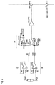
- FIG. 2 is a circuit diagram for describing a first amplification circuit and portions related thereto, of the circuit configuration of the gas sensor control circuit according to Embodiment 1.
- FIG. 3 is a graph relating to a second amplification circuit of an air-fuel ratio detection apparatus according to Embodiment 1, Modification 1 and Modification 2, and showing the relation between pump current Ip or air-fuel ratio AF and second output signal VIP 2 .
- FIG. 4 is a graph relating to a case where the first amplification circuit of a gas sensor control circuit according to Embodiment 1, Modification 1, and Modification 2 is in a first state ST 1 or a third state ST 3 , and showing the relation between pump current Ip or air-fuel ratio AF and first output signal VIP 1 and third output signal VIP 3 .
- FIG. 5 is a flowchart showing specific steps of an air-fuel ratio detection method employed by the air-fuel ratio detection system according to Embodiment 1.
- FIG. 6 is a circuit diagram for describing the circuit configuration of the gas sensor control circuit and the air-fuel ratio detection system according to Modification 1.
- FIG. 7 is an equivalent circuit diagram for describing a rail-to-rail type operational amplifier used in the gas sensor control circuit according to Modification 2.
- FIG. 8 is a schematic example showing a layered structure of a gas sensor element.
- FIGS. 1 to 5 An air-fuel ratio detection system 1 according to a first embodiment of the present invention will be described with reference to FIGS. 1 to 5 .
- the air-fuel ratio detection system 1 which detects air-fuel ratio from exhaust gas of a gasoline engine, includes a gas sensor apparatus 3 composed of a gas sensor element 4 and a gas sensor control circuit 2 which controls the gas sensor element 4 and outputs an output signal corresponding to the air-fuel ratio; and an engine control apparatus (hereinafter also referred to as ECU) 5 which obtains the air-fuel ratio on the basis of the output signal and controls the gasoline engine.
- the gas sensor control circuit 2 is connected to three terminals Vs+, COM, and IP+ of the gas sensor element 4 , via respective terminals Icp+, Vcent, IP+. Further, the gas sensor control circuit 2 is connected to terminals AD 1 , AD 2 , and CT of the ECU 5 via respective terminals VIP 2 , VIP 1 /VIP 3 , and CI.
- the gas sensor element 4 has a known structure, as example of which is shown in FIG. 8 , in which a pump cell 41 and an electromotive force cell 42 are layered via a spacer that forms a hollow measurement chamber 50 into which exhaust gas can be introduced, and an electrode of the electromotive force cell 42 located opposite its side facing the measurement chamber is covered by a shielding layer.
- Each of the pump cell 41 and the electromotive force cell 42 includes, as a substrate, a plate-shaped solid electrolyte 60 having oxygen-ion conductivity, and porous platinum electrodes are formed on opposite sides of the substrate.
- a second electrode 12 a (a right-hand electrode in FIG. 1 ) of the pump cell 41 is connected to the output terminal Ip+of the gas sensor element 4
- a second electrode 13 b (a left-hand electrode in FIG. 1 ) of the electromotive force cell 42 is connected to the terminal Vs+of the gas sensor element 4 .
- pump current Ip flowing through the pump cell 41 is controlled such that a voltage Vs generated across the electromotive force cell 42 becomes 450 mV, whereby oxygen contained in exhaust gas introduced into the measurement chamber is pumped in or pumped out.
- the air-fuel ratio oxygen concentration in exhaust gas
- the ECU 5 includes A/D converters 51 and 52 , and a CPU 53 .
- the A/D converters 51 and 52 receive the output signals of the gas sensor control circuit 2 via the external input terminals AD 1 and AD 2 of the ECU 5 , convert them into digital values, and output the digital values to the CPU 53 .
- the CPU 53 calculates the air-fuel ratio on the basis of the digitized output signals of the gas sensor control circuit 2 . Further, as will be described later, the ECU 5 turns on and off switches SW 2 to SW 4 contained in the gas sensor control circuit 2 , in accordance with the calculated air-fuel ratio.
- the gas sensor control circuit 2 includes a detection resistor Rd which detects the magnitude of the pump current Ip and converts it to a detection voltage Vd, and a detection section 20 which detects and amplifies the detection voltage Vd generated by the detection resistor Rd.
- the control section includes constant-current sources 21 and 25 , an input buffer 22 , an output buffer 26 , and a PID control circuit 23 .
- the constant-current source 21 , the electromotive force cell 42 , a resistor R 1 , and the constant-current source 25 are connected in this sequence so as to form a current path for supplying the very small current Icp.
- the PID control circuit 23 controls the magnitude of the pump current Ip through PID control such that a constant potential difference of 450 mV is produced between the potential at the terminal Vcent and the potential of the terminal Vs+ of the gas sensor element 4 (the Icp+ terminal of the gas sensor control circuit 2 ), which terminal is connected to the PID control circuit 23 via the input buffer 22 .
- capacitors C 1 to C 3 and resistors R 2 to R 4 for determining constants of the PID control are connected to terminals P 1 , P 2 , and Pout, which communicate with the PID control circuit 23 .
- the detection resistor Rd Since the detection resistor Rd is disposed in the current path through which the pump current Ip flows, a detection voltage Vd (V) corresponding to the magnitude of the pump current Ip is generated across the detection resistor Rd.
- the detection voltage Vd can be obtained from the difference between potential Vcent and potential Pout, where potential Vcent represents the potential at one end of the detection resistor Rd (potential at the terminal Vcent), and potential Pout represents the potential at the other end of the detection resistor Rd (potential at the terminal Pout).
- the detection resistor Rd has a predetermined resistance (300 ⁇ ).
- a sensor control circuit designed such that the resistance of a detection resistor is switched every time the resistance of the detection resistor is switched, the state of a path through which pump current flows changes suddenly, and a long period of time is required for PID control to become stable, during which period the output obtained from the detection resistor Rd also becomes instable.
- the gain of an amplification circuit is changed rather than the resistance of the detection resistor Rd. Therefore, the resistance of the detection resistor Rd is fixed, whereby stable PID control of the pump current Ip becomes possible.
- the detection section 20 (output means) of the gas sensor control circuit 2 includes buffers 27 and 28 , a first amplification circuit 29 , and a second amplification circuit 30 .
- the buffer 27 is composed of resistors Ri and an operational amplifier OP 1
- the buffer 28 is composed of resistors Ri and an operational amplifier OP 2 .
- the second amplification circuit 30 is a differential-amplification-type negative feedback amplification circuit composed of an operational amplifier OP 5 , resistors R 5 to R 8 , and a buffer 32 .
- the buffer 32 is composed of an operational amplifier OP 6 .
- the first amplification circuit is a differential-amplification-type negative feedback amplification circuit composed of an operational amplifier OP 3 , resistors R 9 to R 14 , the switches SW 2 , SW 3 , and SW 4 , and a buffer 31 .
- the buffer 31 is composed of an operational amplifier OP 4 .
- the buffer 27 provides buffering operation for the potential Vcent received via an intermediate terminal 20 V
- the buffer 28 provides buffering operation for the potential Pout received via an intermediate terminal 20 P.
- the second amplification circuit 30 will be described.
- the potential Vcent is applied, via the buffer 27 and the resistor R 5 , to a non-inverted input terminal (+ terminal) of the operation amplifier OP 5
- a reference potential OFS 2 is applied to the non-inverted input terminal via the buffer 32 and the resistor R 6 .
- the potential Pout is applied, via the buffer 28 and the resistor R 7 , to an inverted input terminal ( ⁇ terminal) of the operation amplifier OP 5
- the output of the second amplification circuit 30 itself is applied to the inverted input terminal via the resistor R 8 .
- the second amplification circuit 30 constitutes a differential-amplification-type negative feedback amplification circuit which has an offset voltage OFS 2 and in which the resistor R 8 serves as a feedback resistor.
- the second amplification circuit 30 since the second amplification circuit 30 is configured as a differential amplification circuit, noise commonly entering the two input terminals can be properly eliminated, so that a proper second output signal VIP 2 including a reduced amount of noise can be obtained.
- R 5 and R 7 are set to 60 k ⁇
- R 6 and R 8 are set to 270 k ⁇
- V 1 is set to 2.3 V.
- the second amplification circuit 30 constitutes a differential amplification circuit which receives the detection voltage Vd as an input, amplifies it with a second gain G 2 of 4.5 and a second offset voltage OFS 2 of 2.3V, and outputs the second output signal VIP 2 .
- the resistance of the detection resistor Rd is 300 ⁇
- the relation between the pump current Ip (A) and the second output signal VIP 2 (V) is represented by the following equation.
- VIP 2 Ip ⁇ 300 ⁇ 4.5+2.3 Eq. (1)
- FIG. 3 shows the output characteristic of the second amplification circuit 30 ; i.e., the second output signal VIP 2 which is determined on the basis of Eq. (1).
- the horizontal axis represents the pump current Ip (unit: mA) and air-fuel ratio AF (unit: A/F) corresponding thereto.
- the vertical axis represents the second output signal VIP 2 (unit: V).
- the left side of the stoichiometric ratio is a rich region, and the right side thereof is a lean region.
- An operational amplifier having an ordinary output-stage circuit configuration is used for the operational amplifier OP 5 of the second amplification circuit 30 . It is known that in such an operational amplifier, due to voltage drops of transistors at the final stage, the maximum output voltage becomes about 1.0 to 1.3 V lower than the power supply voltage, and the minimum output voltage becomes about 0.3 to 0.7 V higher than the ground potential.
- the operational amplifiers OP 3 and OP 5 which constitute the second amplification circuit 30 and the first amplification circuit 29 , respectively, have an output voltage range of 0.3 to 4.0 V. Accordingly, the output voltage range of the second output signal VIP 2 of the second amplification circuit 30 is limited to 0.3 to 4.0 V. Therefore, in the graph shown in FIG. 3 , the second output signal VIP 2 has a characteristic such that the second output signal VIP 2 is clipped at 0.3 V, which is the minimum value of the output voltage, and at 4.0 V, which is the maximum value of the output voltage.
- the second output signal VIP 2 obtained in the second amplification circuit 30 is output from the terminal VIP 2 of the gas sensor control circuit 2 and then input to the terminal AD 1 of the ECU 5 , and is converted into a digital value by means of the A/D converter 51 .
- the digital value is processed by means of the CPU 53 , and is utilized for, for example, fuel control of the gasoline engine.
- the second output signal VIP 2 is always input to the ECU 5 .
- the first amplification circuit 29 is a differential-amplification-type negative feedback amplification circuit using an operational amplifier. Accordingly, noise commonly entering the two input terminals of the first amplification circuit 30 can be properly eliminated, so that a proper first output signal VIP 1 including a reduced amount of noise can be obtained. This is the same as in the case of the second amplification circuit 30 .
- the first amplification circuit 29 differs from the second amplification circuit 30 in that the first amplification circuit 29 includes a circuit for switching the resistance by use of the switches SW 2 , etc.
- the first amplification circuit 29 and a circuit related thereto will be described in detail with reference to FIG. 2 .
- the buffers 27 and 28 have already been described.
- the potential Vcent is applied, via the buffer 27 and the resistor R 9 , to a non-inverted input terminal (+ terminal) of the operation amplifier OP 3 , and the output of the buffer 31 is applied to the non-inverted input terminal via the resistor R 11 .
- a circuit including the switch SW 3 and the resistor R 12 serially connected to each other is connected in parallel to the resistor R 11 .
- the resistance between the non-inverted input terminal of the first amplification circuit 29 and the buffer 31 can be switched between the resistance of the resistor R 11 and the composite resistance of the resistors R 11 and R 12 connected in parallel.
- this first amplification circuit 29 through switching of the resistance by means of the switch SW 3 , there is established matching between the impedance connected to the non-inverted input terminal + and the impedance connected to the inverted input terminal ( ⁇ terminal) as will be described later.
- the buffer 31 is composed of the operational amplifier OP 4 , and can receive, as an input, one of a reference potential OFS 1 and a reference potential OFS 3 , which is selected by means of the switch SW 2 , and output the reference potential OFS 1 or the reference potential OFS 3 , whichever is received as an input.
- This reference potential OFS 1 , OFS 3 determines the offset voltage (first and third offset voltages OFS 1 and OFS 3 ) of the first amplification circuit 29 . That is, in the first amplification circuit 29 , the switch SW 2 serves as an offset change means for selecting one of two offset voltages.
- the potential Pout is applied, via the buffer 28 and the resistor R 10 , to an inverted input terminal ( ⁇ terminal) of the first amplification circuit 29 , and the output of the first amplification circuit 29 itself is applied to the inverted input terminal via the resistor R 13 .
- a circuit including the switch SW 4 and the resistor 14 serially connected to each other is connected in parallel to the resistor R 13 . Therefore, through an operation of turning the switch SW 4 on and off, the resistance of the feedback resistor present between the inverted input terminal of the first amplification circuit 29 and the output of the first amplification circuit 29 itself can be switched between the resistance of the resistor R 13 and the composite resistance of the resistors R 13 and R 14 connected in parallel.
- the gain of the first amplification circuit 29 can be changed. That is, through synchronous switching of the switches SW 3 and SW 4 , the gain can be switched to one of two gains, and these switches serve as a changeover means. Moreover, the present Embodiment 1 is configured such that the switch SW 2 can be switched in synchronism with the switches SW 3 and SW 4 , so that the offset voltage can be changed also.
- the first amplification circuit 29 can be switched between a first state ST 1 in which a first gain G 1 and a first output voltage VIP 1 having a first offset voltage OFS 1 are obtained, and a third state ST 3 in which a third gain G 3 and a third output voltage VIP 3 having a third offset voltage OFS 3 are obtained.
- This state switching is effected through switching of the switches SW 2 to SW 4 in an interlocked manner. Specifically, when the first amplification circuit 29 is to be brought into the third state ST 3 , the switch SW 2 is switched to the reference potential OFS 3 side, and the switches SW 3 and SW 4 are turned off.
- the switches SW 3 and SW 4 correspond to the claimed changeover means. Meanwhile, when the first amplification circuit 29 is to be brought into the first state ST 1 , the switch SW 2 is switched to the reference potential OFS 1 side, and the switches SW 3 and SW 4 are turned on. Notably, these switches SW 2 to SW 4 are turned on and off by means of a command input which is input from a communication output terminal CT of the ECU 5 via a communication input terminal CI of the gas sensor control circuit 2 in accordance with a control program executed by the CPU 53 of the ECU 5 .
- the output signal output from the first amplification circuit 29 via the terminal VIP 1 /VIP 3 will be referred to as follows.
- the output signal output from the first amplification circuit 29 in the first state ST 1 will be referred to as a first output signal VIP 1
- the output signal output from the first amplification circuit 29 in the third state ST 3 will be referred to as a third output signal VIP 3 .
- the signal output from the first amplification circuit 29 is to be denoted by the same name irrespective of whether the first amplification circuit 29 is in the first or third state, the signal will be referred to as the output signal VIP 1 - 3 .
- the first amplification circuit 29 using a single operational amplifier OP 3 is configured such that the gain and offset voltage can be changed by use of the switches SW 2 to SW 4 . Therefore, as compared with a case where two amplification circuits which differ in gain and offset voltage are provided in order to obtain the first and third output signals, the number of operation amplifiers can be reduced, whereby the air-fuel ratio detection system 1 can be reduced in circuit size and power consumption, and can be made inexpensive.
- the relation between the pump current Ip (A) and the first output signal VIP 1 (V) in the first state and the relation between the pump current Ip (A) and the third output signal VIP 3 (V) in the third state are represented by the following equations, respectively.
- VIP 1 Ip ⁇ 300 ⁇ 1.5+2.0 Eq.
- VIP 3 Ip ⁇ 300 ⁇ 4.5+0.4 Eq. (3)
- FIG. 4 shows the output characteristic of the first amplification circuit 29 ; i.e., the first output signal VIP 1 which is output from the first amplification circuit 29 in the first state ST 1 and is determined on the basis of Eq. (2), and the third output signal VIP 3 which is output from the first amplification circuit 29 in the third state ST 3 and is determined on the basis of Eq. (3).
- the horizontal axis represents the pump current Ip (unit: mA) and air-fuel ratio AF (unit: A/F) corresponding thereto.
- the vertical axis represents the first and third output signals VIP 1 and VIP 3 (unit: V).
- the point at which the pump current Ip becomes 0 mA corresponds to the stoichiometric ratio
- the left side of the stoichiometric ratio is a rich region
- the right side thereof is a lean region.
- each of the first output signal VIP 1 and the third output signal VIP 3 has a characteristic such that it is clipped at 0.3 V, which is the minimum value of the output voltage, and at 4.0 V, which the maximum value of the output voltage.
- use of the third state of the first amplification circuit 29 allows for obtainment of the third output signal VIP 3 which changes with the air-fuel ratio at least within the third air-fuel ratio zone AFZ 3 .
- the third air-fuel ratio zone AFZ 3 is contained in the first air-fuel ratio zone AFZ 1 .
- the second output signal VIP 2 can be obtained from the second amplification circuit 30 , and through changeover of the switches SW 2 to SW 4 , the first output signal VIP 1 or the third output signal VIP 3 can be obtained from the first amplification circuit 29 .
- the first output signal VIP 1 or the third output signal VIP 3 obtained in the first amplification circuit 29 is output from the terminal VIP 1 /VIP 3 of the gas sensor control circuit 2 via the buffer 33 and then input to the terminal AD 2 of the ECU 5 , and is converted into a digital value by means of the A/D converter 52 .
- the digital value is processed by means of the CPU 53 , and is utilized for, for example, fuel control of the gasoline engine.
- the first output signal VIP 1 and the third output signal VIP 3 are selectively input to the ECU 5 .
- the ratio of a change in the output signal to a change in the air-fuel ratio AF can be increased. Therefore, use of the second output voltage VIP 2 or the third output voltage VIP 3 enables the air-fuel ratio to be detected more accurately in the second air-fuel ratio zone AFZ 2 in the vicinity of the stoichiometric ratio and the third air-fuel ratio zone AFZ 3 in the lean region.
- air-fuel ratio detection system 1 gas sensor apparatus 3 of the present Embodiment 1
- gas sensor apparatus 3 gas sensor apparatus 3
- the air-fuel ratio detection system 1 gas sensor apparatus 3 of the present Embodiment 1
- air-fuel ratio at least in the second air-fuel ratio zone AFZ 2 and the third air-fuel ratio zone AFZ 3 can be detected accurately. Therefore, proper control can be performed through accurate detection of air-fuel ratio in all of the case of stoichiometric burn control, the case of lean burn control, and the case where control shifts from the stoichiometric burn control to the lean burn control.
- air-fuel ratio can be detected within a wide air-fuel ratio range (first air-fuel ratio zone AFZ 1 ) by use of the first output signal VIP 1 only. Accordingly, air-fuel ratio can be detected properly even when burning in the rich region occurs, for example, during acceleration of an automobile or even when the air-fuel ratio greatly changes before and after occurrence of burning in the rich region.
- air-fuel ratio AF can be properly obtained in each of various burn controls such as stoichiometric burn control, lean burn control, and burn control in the rich region.
- step 52 the CPU obtains the second output signal VIP 2 output from the second amplification circuit 30 . Specifically, the CPU fetches a digital value of the voltage of the second output signal VIP 2 converted by means of the A/D converter 51 in the ECU 5 .
- step 53 the CPU determines whether or not the second output signal VIP 2 obtained in step 52 is greater than a second upper limit voltage VAF 2 U (in the present example, 3.7 V) corresponding to the second upper limit AF 2 U. Specifically, this determination is performed through comparison between the second upper limit voltage VAF 2 U and the digital value of the voltage of the second output signal VIP 2 fetched in the ECU 5 in step 51 . When the result of the comparison shows that the second output signal VIP 2 is greater than the second upper limit voltage VAF 2 U (Yes), the CPU proceeds to step 54 . If not (No), the CPU determines that the second output signal VIP 2 is equal to or less than the second upper limit voltage VAF 2 U, and proceeds to step 59 .
- a second upper limit voltage VAF 2 U in the present example, 3.7 V
- step 59 the CPU determines whether or not the second output signal VIP 2 obtained in step 52 is less than a second lower limit voltage VAF 2 L (in the present example, 1.2 V) corresponding to the second lower limit AF 2 L.
- a second lower limit voltage VAF 2 L in the present example, 1.2 V
- the CPU proceeds to step 56 . If not (No), the CPU determines that the second output signal VIP 2 assumes a value which is equal to or greater than the second lower limit voltage VAF 2 L and which corresponds to an air-fuel ratio within the second air-fuel ratio zone AFZ 2 , and then proceeds to step 510 .
- step 510 the CPU calculates the air-fuel ratio AF in accordance with Eq. (1) and by use of the second output signal VIP 2 in the ECU 5 . After completion of the calculation of the air-fuel ratio AF, the CPU returns to step 52 .
- step 54 the CPU obtains the third output signal VIP 3 output from the first amplification circuit 29 in the third state. Specifically, the CPU fetches a digital value of the voltage of the third output signal VIP 3 converted by means of the A/D converter 52 in the ECU 5 . Further, in step 55 , the CPU determines whether or not the third output signal VIP 3 obtained in step 54 is greater than a third upper limit voltage VAF 3 U (in the present example, 3.1 V) corresponding to the third upper limit AF 3 U. Specifically, this determination is performed through comparison between the third upper limit voltage VAF 3 U and the digital value of the voltage of the third output signal VIP 3 fetched in the ECU 5 in step 54 .
- a third upper limit voltage VAF 3 U in the present example, 3.1 V
- step 56 the CPU determines that the third output signal VIP 3 assumes a value which is equal to or less than the third upper limit voltage VAF 3 U and corresponds to an air-fuel ratio within the third air-fuel ratio zone AFZ 3 , and then proceeds to step 511 .
- step 511 the CPU calculates the air-fuel ratio AF in accordance with Eq. (3) and by use of the third output signal VIP 3 in the ECU 5 . After completion of the calculation of the air-fuel ratio AF, the CPU returns to step 52 .
- steps 56 to 58 are performed when the second output signal VIP 2 obtained in step 52 or the third output signal VIP 3 obtained in step 54 shows that the air-fuel ratio AF is contained in neither the second air-fuel ratio zone AFZ 2 nor the third air-fuel ratio zone AFZ 3 .
- the air-fuel ratio is detected by use of the first output signal VIP 1 corresponding to the widest first air-fuel ratio zone AFZ 1 .
- step 57 the CPU obtains the first output signal VIP 1 output from the first amplification circuit 29 in the first state. Specific steps are similar to those in step 54 .
- step 58 the CPU calculates the air-fuel ratio AF in accordance with Eq. (2) and by use of the first output signal VIP 1 in the ECU 5 . After completion of the calculation of the air-fuel ratio AF, the CPU returns to step 51 , in which the first amplification circuit 29 is brought into the third state.
- the air-fuel ratio AF is calculated on the basis of the second output signal VIP 2 output from the second amplification circuit 30 . Further, when the air-fuel ratio AF to be detected is contained in the third air-fuel ratio zone AFZ 3 , the air-fuel ratio AF is calculated on the basis of the third output signal VIP 3 output from the first amplification circuit 29 in the third state.
- the first amplification circuit 29 operates while remaining in the third state ST 3 . That is, in this case, the processing (step 56 or 51 ) for switching the first amplification circuit 29 between the first and third states is not performed, and the air-fuel ratio AF can be detected with high responsiveness.
- the air-fuel ratio detection system 100 shown in FIG. 6 includes a gas sensor apparatus 130 and an ECU 5 similar to that used in Embodiment 1.
- the gas sensor apparatus 130 includes a gas sensor element 120 ; a gas sensor control circuit 110 which controls voltage applied to the gas sensor element 120 and includes a detection section 20 similar to that used in Embodiment 1; and a control computer 140 for controlling the gas sensor control circuit 110 .
- the ECU 5 obtains air-fuel ratio AF on the basis of an output signal of the gas sensor control circuit 110 .
- the one-cell-type gas sensor element 120 includes an oxygen-ion conductive solid electrolyte body having the shape of a bottomed cylinder, and Pt electrode layers formed on the inner and outer surfaces of the solid electrolyte body. A porous diffusion resistance layer is formed on the electrode located on the outer side. In a region on the lean side of the stoichiometric air-fuel ratio, the gas sensor element 120 generates a limiting current (sensor current I 2 ) corresponding to the oxygen concentration of exhaust gas, upon application of voltage, which application is commanded from the control computer 140 .
- the concentrations of unburned gases change approximately linearly, and the gas sensor element 120 generates a limiting current (sensor current I 2 ) corresponding to the concentrations of CO, HC, etc.
- the respective electrode layers are connected to external connection terminals 120 t and 120 s .
- these external connection terminals 120 t and 120 s are connected to gas sensor control terminals 110 t and 110 s of the gas sensor control circuit 110 .
- the gas sensor control circuit 110 includes resistors R 105 and R 106 for dividing a power supply voltage Vcc to thereby generate a reference voltage Va; operational amplifiers 101 and 102 ; and a detection resistor Rd 2 .
- the reference voltage Va generated by the resistors R 105 and R 106 is applied to a non-inverted input terminal of the operational amplifier 101 , and the output terminal of the operational amplifier 101 is connected to the gas sensor control terminal 110 t via the detection resistor Rd 2 . Further, an inverted input terminal of the operational amplifier 101 is connected to the gas sensor control terminal 110 t . Therefore, the potential of the gas sensor control terminal 110 t is controlled such that it becomes equal to the reference voltage Va.
- the control computer 140 includes not only a CPU 143 but also an A/D converter 141 and a D/A converter 142 .
- the CPU 143 fetches a voltage (potential difference) Vd 2 across the detection resistor Rd 2 via the A/D converter 141 , and detects the sensor current I 2 flowing through the gas sensor element 120 from this potential difference Vd 2 .
- the CPU 143 then calculates an optimal voltage command value to be applied to the gas sensor element 120 in accordance with the sensor current I 2 .
- the voltage command value calculated by the CPU 143 is converted to a command voltage Vb at the D/A converter 142 , and the command voltage Vb is input to the operational amplifier 102 .
- the output of the D/A converter 142 is input to a non-inverted input terminal of the operational amplifier 102 , and the output of the operational amplifier 102 is input to an inverted input terminal thereof. Therefore, this operational amplifier 102 operates as a buffer. Accordingly, the command voltage Vb is applied to the external connection terminal 120 s of the gas sensor element 120 via the gas sensor control terminal 110 s.
- the reference voltage Va is applied to the external connection terminal 120 t of the gas sensor element 120
- the command voltage Vb is applied to the external connection terminal 120 s thereof.
- the current I 2 flowing through the gas sensor element 120 can be detected as a potential difference Vd 2 (Vc ⁇ Va) across the detection resistor Rd 2 .
- the reference voltage Va and the command voltage Vb are controlled such that when the detected air-fuel ratio AF is 14.6 (stoichiometric ratio), the sensor current I 2 becomes 0 (mA).
- the detection section 20 similar to that used in the air-fuel ratio detection system 1 (gas sensor apparatus 3 ) according to Embodiment 1 is connected so as to detect the potential difference (detection voltage) Vd 2 across the detection resistor Rd 2 via an intermediate terminals 20 P and 20 V. Accordingly, as in Embodiment 1, the first gain G 1 , the second gain G 2 , the third gain G 3 , the first offset voltage OFS 1 , the second offset voltage OFS 2 , and the third offset voltage OFS 3 are set in accordance with the characteristic (detection signal) of the gas sensor element 120 .
- the air-fuel ratio AF can be detected at least within the wide first air-fuel ratio zone AFZ 1 . Further, through use of the second output voltage VIP 2 from the second amplification circuit 30 , the air-fuel ratio AF can be accurately detected at least within the narrow second air-fuel ratio zone AFZ 2 near the stoichiometric ratio. Moreover, through use of the third output signal VIP 3 from the first amplification circuit 29 in the third state, the air-fuel ratio AF can be accurately detected at least within the narrow third air-fuel ratio zone AFZ 3 in the lean region (see FIGS. 1 and 2 ). Accordingly, as in Embodiment 1, the present Modification 1 enables the air-fuel ratio to be detected with proper accuracy in accordance with a range in which the air-fuel ratio AF is measured.
- the air-fuel ratio detection system (gas sensor apparatus) of the present Modification 2 differs in that in place of an operational amplifier having an ordinary output-stage circuit configuration, an operational amplifier 200 (see FIG. 7 ) having a rail-to-rail type output stage is used for the operational amplifiers OP 3 , OP 5 , and OP 7 used in the first amplification circuit 29 , the second amplification circuit 30 , and the buffer 33 (see FIG. 1 ). Accordingly, in the present Modification 2, only different portions will be described, and descriptions of the same portions will not be repeated or will be simplified.
- This operational amplifier 200 is connected at its positive-side power supply terminal to a battery power supply, and operates at the power supply voltage VB (12 V); i.e., operates with a single power supply.
- This operational amplifier 200 includes an input stage circuit 201 , an intermediate amplification stage circuit 202 , a constant-current circuit CP 2 for supplying current to the intermediate amplification stage circuit 202 , a bias circuit 203 , a constant-current circuit CP 3 for supplying current to the bias circuit 203 , and an output stage circuit composed of NPN transistors T 5 and T 6 connected to an output terminal Vo.
- the input stage circuit 201 has a circuit configuration similar to that of an ordinary operational amplifier circuit, and includes a pair of PNP transistors T 1 and T 2 , a constant-current circuit CP 1 connected to the emitter terminals of these transistors, and a pair of NPN transistors T 3 and T 4 connected to the collector terminals of the PNP transistors T 1 and T 2 . Further, input signals IN+ and IN ⁇ are input to the bases of the NPN transistors T 3 and T 4 of the input stage circuit 201 .
- the PNP transistors T 1 and T 2 are driven by means of a constant current I 1 of the constant-current circuit CP 1 , and collector currents of the PNP transistors T 1 and T 2 change in accordance with the voltage difference between the input signals IN+ and IN ⁇ . Further, with changes in the collector currents of the PNP transistors T 1 and T 2 , the NPN transistors T 3 and T 4 operate as follows. That is, when the voltages of the input signals IN+ and IN ⁇ satisfy a relation IN+>IN ⁇ , the collector current of the PNP transistor T 2 increases, and the collector voltage of the NPN transistor T 4 increases.
- the collector voltage of the NPN transistor T 4 is transmitted to the intermediate amplification stage circuit 202 as a signal SG 1 , and amplified by the intermediate amplification stage circuit 202 .
- the amplified signal SG 1 is transmitted to the bias circuit 203 as a signal SG 2 .
- the bias circuit 203 is driven by means of a constant current I 2 from the constant-current circuit CP 3 , and operates the NPN transistors T 5 and T 6 in accordance with the signal SG 2 so that a signal is output from the output terminal Vo.
- the bias circuit 203 turns the NPN transistor T 5 on and turns the NPN transistor T 6 off so as to increase the output voltage at the output terminal Vo. Meanwhile, when IN+ ⁇ IN ⁇ , the bias circuit 203 turns the NPN transistor T 5 off and turns the NPN transistor T 6 on so as to decrease the output voltage at the output terminal Vo.
- the range of output voltage at the output terminal Vo becomes 0.4 V to 10.7 V.
- the input voltage range of the A/D converters 51 and 52 is 0 V to 5 V
- the substantial operational range of the operational amplifier 200 for detection of air-fuel ratio AF becomes 0.4 V to 5.0 V. Accordingly, in the rail-to-rail type operational amplifier 200 , the output range is expanded on the maximum output voltage side, as compared with the output range of an ordinary operational amplifier ( 0.4 V to 4.0 V).
- the output voltage characteristic in the case where the rail-to-rail type operational amplifier 200 is used for the operational amplifier OP 5 of the second amplification circuit 30 is shown by a broken line PR 1 in FIG. 3 .
- an operation amplifier having an ordinary output-stage configuration is used for the operational amplifier OP 5 of the second amplification circuit 30 , its maximum output voltage becomes 4.0 V, so that the maximum value of the detectable pump current Ip is 1.3 mA (corresponding to an air-fuel ratio AF of 22 ).
- the maximum output voltage is increased to 5.0 V, whereby the maximum value of the detectable pump current Ip can be increased to 2.0 mA (corresponding to an air-fuel ratio AF of 30).
- the output voltage characteristic associated with the third output signal VIP 3 in the case where the rail-to-rail type operational amplifier 200 is used for the operational amplifier OP 3 of the first amplification circuit 29 is shown by a broken line PR 2 in FIG. 4 .
- This broken line PR 2 shows the characteristic of the first amplification circuit 29 when it is in the third state.
- the maximum output voltage becomes 4.0 V, so that the maximum value of the detectable pump current Ip is 2.7 mA (corresponding to an air-fuel ratio AF of 60).
- the maximum output voltage is increased to 5.0 V, whereby the maximum value of the detectable pump current Ip can be increased to 3.4 mA (corresponding to an air-fuel ratio AF of 100).
- the third output signal of the first amplification circuit 29 having a detection range expanded as described above can be output as is.
- the air-fuel ratio detection system gas sensor apparatus
- Modification 2 in which the rail-to-rail type operational amplifier 200 is applied to the amplifiers used in the first amplification circuit 29 , the second amplification circuit 30 , and the buffer 33 , the first output signal VIP 1 , the second output signal VIP 2 , and the third output signal VIP 3 , which change in accordance with the detection signal of the gas sensor, can be output in a wider detection range.
- the pump current Ip air-fuel ratio AF
- the rail-to-rail type operational amplifier 200 is used in the second amplification circuit 30 .
- similar operation and effects can be attained even when the rail-to-rail type operational amplifier 200 is used in the first amplification circuit 29 .
- Embodiment 1 and Modification 2 exemplify the air-fuel ratio detection system 1 which includes the gas sensor control circuit 2 using a two-cell-type gas sensor element
- Modification 1 exemplifies the air-fuel ratio detection system 100 which includes the gas sensor control circuit 110 using a one-cell-type gas sensor element
- the present invention can be applied to a gas sensor control circuit using a gas sensor element of another form (e.g., a gas sensor element including three or more cells).
- the means for converting a change in current flowing through a cell to a change in voltage is not limited to a detection resistor, and it may be means for detecting induction current, for example.
- Modification 2 exemplifies the case where the rail-to-rail type operational amplifier is formed by use of bipolar elements (PNP transistors and NPN transistors).
- bipolar elements PNP transistors and NPN transistors
- semiconductor elements which can operate similarly, such as MOSFETs and gallium arsenide transistor elements may be used.
Landscapes
- Engineering & Computer Science (AREA)
- Chemical & Material Sciences (AREA)
- Combustion & Propulsion (AREA)
- Mechanical Engineering (AREA)
- General Engineering & Computer Science (AREA)
- Computer Hardware Design (AREA)
- Microelectronics & Electronic Packaging (AREA)
- Combined Controls Of Internal Combustion Engines (AREA)
Abstract
Description
- 1, 100: air-fuel ratio detection system (air-fuel ratio detection apparatus)
- 2, 110: gas sensor control circuit (sensor control apparatus)
- 4, 120: gas sensor element
- 3, 130: gas sensor apparatus
- 20: detection section (output means)
- OP1, OP2, OP3, OP4, OP5, OP6: operational amplifier
- 29: first amplification circuit
- 30: second amplification circuit
- 41: pump cell
- 42: electromotive force cell
- 200: (rail-to-rail type) operational amplifier
- AF1L: first lower limit
- AF1U: first upper limit
- AF2L: second lower limit
- AF2U: second upper limit
- AF3L: third lower limit
- AF3U: third upper limit
- AFZ1: first air-fuel ratio zone
- AFZ2: second air-fuel ratio zone
- AFZ3: third air-fuel ratio zone
- VAF1L: first lower limit voltage
- VAF1U: first upper limit voltage
- VAF2L: second lower limit voltage
- VAF2U: second upper limit voltage
- VAF3L: third lower limit voltage
- VAF3U: third upper limit voltage
- G1: first gain
- G2: second gain
- G3: third gain
- OFS1, OFS2, OFS3: offset voltage, reference potential
- SW2: switch (offset changing means)
- SW3, SW4: (changeover means)
- VIP2: second output signal
- VIP1-3: output signal of the first amplification circuit
- VIP1: first output signal
- VIP3: third output signal
- Vd, Vd2: detection voltage (detection signal)
VIP2=Ip×300×4.5+2.3 Eq. (1)
VIP1=Ip×300×1.5+2.0 Eq. (2)
VIP3=Ip×300×4.5+0.4 Eq. (3)
Claims (9)
Priority Applications (1)
| Application Number | Priority Date | Filing Date | Title |
|---|---|---|---|
| US11/870,867 US7802463B2 (en) | 2007-10-11 | 2007-10-11 | Sensor control device and air fuel ratio detecting apparatus |
Applications Claiming Priority (1)
| Application Number | Priority Date | Filing Date | Title |
|---|---|---|---|
| US11/870,867 US7802463B2 (en) | 2007-10-11 | 2007-10-11 | Sensor control device and air fuel ratio detecting apparatus |
Publications (2)
| Publication Number | Publication Date |
|---|---|
| US20090095052A1 US20090095052A1 (en) | 2009-04-16 |
| US7802463B2 true US7802463B2 (en) | 2010-09-28 |
Family
ID=40532849
Family Applications (1)
| Application Number | Title | Priority Date | Filing Date |
|---|---|---|---|
| US11/870,867 Active 2028-12-08 US7802463B2 (en) | 2007-10-11 | 2007-10-11 | Sensor control device and air fuel ratio detecting apparatus |
Country Status (1)
| Country | Link |
|---|---|
| US (1) | US7802463B2 (en) |
Cited By (1)
| Publication number | Priority date | Publication date | Assignee | Title |
|---|---|---|---|---|
| US20120210174A1 (en) * | 2009-10-13 | 2012-08-16 | Ngk Spark Plug Co., Ltd. | Sensor control device and sensor control method |
Families Citing this family (10)
| Publication number | Priority date | Publication date | Assignee | Title |
|---|---|---|---|---|
| US7655121B2 (en) * | 2006-05-23 | 2010-02-02 | Ngk Spark Plug Co., Ltd. | Gas sensor interface device and gas sensor system |
| JP4874918B2 (en) * | 2007-10-01 | 2012-02-15 | 日本特殊陶業株式会社 | Gas sensor abnormality diagnosis method, gas sensor abnormality diagnosis device |
| JP5054795B2 (en) * | 2010-03-23 | 2012-10-24 | 日立オートモティブシステムズ株式会社 | Fuel supply control device for internal combustion engine |
| CN102612279A (en) * | 2011-01-19 | 2012-07-25 | 鸿富锦精密工业(深圳)有限公司 | Server cabinet |
| ITTO20110258A1 (en) * | 2011-03-24 | 2012-09-25 | Eltek Spa | SENSOR AND / OR DUCT FOR DETECTION OF LIQUIDS, IN PARTICULAR FUELS FOR VEHICLES |
| DE102011086829A1 (en) * | 2011-11-22 | 2013-05-23 | Continental Automotive Gmbh | On-board network and method for operating a vehicle electrical system |
| WO2014118893A1 (en) | 2013-01-29 | 2014-08-07 | トヨタ自動車株式会社 | Control device for internal combustion engine |
| CN104981600B (en) * | 2013-01-29 | 2017-08-25 | 丰田自动车株式会社 | The control device of internal combustion engine |
| JP6500715B2 (en) * | 2015-09-09 | 2019-04-17 | 株式会社デンソー | Controller for air-fuel ratio sensor |
| WO2020012929A1 (en) * | 2018-07-13 | 2020-01-16 | 日立オートモティブシステムズ株式会社 | In-vehicle electronic control device |
Citations (13)
| Publication number | Priority date | Publication date | Assignee | Title |
|---|---|---|---|---|
| JPS6218659U (en) | 1985-07-17 | 1987-02-04 | ||
| JPS62203056A (en) | 1986-03-03 | 1987-09-07 | Honda Motor Co Ltd | Oxygen concentration detector |
| JPH01152356A (en) | 1987-12-09 | 1989-06-14 | Honda Motor Co Ltd | Air-fuel ratio detector |
| US4915813A (en) | 1987-12-09 | 1990-04-10 | Honda Giken Kogyo Kabushiki Kaisha | Oxygen concentration detecting device |
| US5475339A (en) * | 1994-05-06 | 1995-12-12 | National Semiconductor Corporation | Op amp with rail to rail output swing and employing an improved current mirror circuit |
| JPH0961397A (en) | 1995-08-30 | 1997-03-07 | Denso Corp | Air-fuel ratio detector |
| JPH09145671A (en) | 1995-11-17 | 1997-06-06 | Yazaki Corp | Oxygen sensor sensor characteristic adjustment circuit |
| US5778855A (en) * | 1997-07-03 | 1998-07-14 | Ford Global Technologies, Inc. | Combustion stability control for lean burn engines |
| US5980710A (en) | 1997-05-21 | 1999-11-09 | Denso Corporation | Method and apparatus for gas concentration detection and manufacturing method of the apparatus |
| JP2000046791A (en) | 1998-05-29 | 2000-02-18 | Denso Corp | Gas concentration detector |
| US20040089545A1 (en) | 2002-11-08 | 2004-05-13 | Denso Corporation | High-resolution gas concentration measuring apparatus |
| JP2006275628A (en) * | 2005-03-28 | 2006-10-12 | Ngk Spark Plug Co Ltd | Sensor control device and air-fuel ratio detection device |
| US7252748B2 (en) * | 2002-06-28 | 2007-08-07 | Ngk Spark Plug Co., Ltd. | NOx measurement apparatus |
-
2007
- 2007-10-11 US US11/870,867 patent/US7802463B2/en active Active
Patent Citations (17)
| Publication number | Priority date | Publication date | Assignee | Title |
|---|---|---|---|---|
| JPS6218659U (en) | 1985-07-17 | 1987-02-04 | ||
| JPS62203056A (en) | 1986-03-03 | 1987-09-07 | Honda Motor Co Ltd | Oxygen concentration detector |
| JPH01152356A (en) | 1987-12-09 | 1989-06-14 | Honda Motor Co Ltd | Air-fuel ratio detector |
| US4915813A (en) | 1987-12-09 | 1990-04-10 | Honda Giken Kogyo Kabushiki Kaisha | Oxygen concentration detecting device |
| US5475339A (en) * | 1994-05-06 | 1995-12-12 | National Semiconductor Corporation | Op amp with rail to rail output swing and employing an improved current mirror circuit |
| US5810997A (en) | 1995-08-30 | 1998-09-22 | Nippondenso Co., Ltd. | Air-fuel ratio detection with variable detection range |
| JPH0961397A (en) | 1995-08-30 | 1997-03-07 | Denso Corp | Air-fuel ratio detector |
| JPH09145671A (en) | 1995-11-17 | 1997-06-06 | Yazaki Corp | Oxygen sensor sensor characteristic adjustment circuit |
| US5980710A (en) | 1997-05-21 | 1999-11-09 | Denso Corporation | Method and apparatus for gas concentration detection and manufacturing method of the apparatus |
| JP3487159B2 (en) | 1997-05-21 | 2004-01-13 | 株式会社デンソー | Gas concentration detection device and method of manufacturing the same |
| US5778855A (en) * | 1997-07-03 | 1998-07-14 | Ford Global Technologies, Inc. | Combustion stability control for lean burn engines |
| JP2000046791A (en) | 1998-05-29 | 2000-02-18 | Denso Corp | Gas concentration detector |
| US6446488B1 (en) | 1998-05-29 | 2002-09-10 | Denso Corporation | Gas concentration measuring apparatus producing current signals as a function of gas concentration |
| US7252748B2 (en) * | 2002-06-28 | 2007-08-07 | Ngk Spark Plug Co., Ltd. | NOx measurement apparatus |
| US20040089545A1 (en) | 2002-11-08 | 2004-05-13 | Denso Corporation | High-resolution gas concentration measuring apparatus |
| JP2004205488A (en) | 2002-11-08 | 2004-07-22 | Denso Corp | Gas concentration detector |
| JP2006275628A (en) * | 2005-03-28 | 2006-10-12 | Ngk Spark Plug Co Ltd | Sensor control device and air-fuel ratio detection device |
Cited By (2)
| Publication number | Priority date | Publication date | Assignee | Title |
|---|---|---|---|---|
| US20120210174A1 (en) * | 2009-10-13 | 2012-08-16 | Ngk Spark Plug Co., Ltd. | Sensor control device and sensor control method |
| US9086393B2 (en) * | 2009-10-13 | 2015-07-21 | Ngk Spark Plug Co., Ltd. | Sensor control device and sensor control method |
Also Published As
| Publication number | Publication date |
|---|---|
| US20090095052A1 (en) | 2009-04-16 |
Similar Documents
| Publication | Publication Date | Title |
|---|---|---|
| US7802463B2 (en) | Sensor control device and air fuel ratio detecting apparatus | |
| US6083370A (en) | Gas sensor | |
| KR910006224B1 (en) | Air-fuel ratio detection device | |
| US8333875B2 (en) | Sensor control device | |
| US7416649B2 (en) | Oxygen concentration detection system and vehicle control system having the same | |
| CN101241099B (en) | Sensor control device | |
| JPH10185861A (en) | Air-fuel ratio detector | |
| US7964073B2 (en) | Air fuel ratio detection apparatus | |
| US20130319857A1 (en) | Gas sensor control apparatus | |
| JP4177345B2 (en) | Sensor control device and air-fuel ratio detection device | |
| JP4872198B2 (en) | Gas concentration detector | |
| US7655121B2 (en) | Gas sensor interface device and gas sensor system | |
| US20120318045A1 (en) | Oxygen concentration sensor input device | |
| US8166800B2 (en) | Gas concentration detection apparatus and gas concentration detection system | |
| US5429105A (en) | Current replication circuit and method for use in exhaust gas oxygen monitoring | |
| EP0974835B1 (en) | Gas concentration measuring apparatus producing current signal as a function of gas concentration | |
| US7052596B2 (en) | Linear lambda probe evaluation circuit | |
| US6300753B1 (en) | Circuit for a NOx measurement sensor | |
| US9933389B2 (en) | Sensor control apparatus and gas detection system | |
| US20160356753A1 (en) | Sensor control apparatus and gas detection system | |
| US6497135B1 (en) | Controller for use with wide range oxygen sensor | |
| US20150362457A1 (en) | Control unit for a gas concentration sensor | |
| JP2011027756A (en) | Gas concentration detection device | |
| US5849175A (en) | Method and circuit arrangement for acutating a measuring sensor to determine an oxygen concentration in a gas mixture | |
| JP2007205819A (en) | Gas concentration detection system |
Legal Events
| Date | Code | Title | Description |
|---|---|---|---|
| AS | Assignment |
Owner name: NGK SPARK PLUG CO., LTD., JAPAN Free format text: ASSIGNMENT OF ASSIGNORS INTEREST;ASSIGNORS:INOUE, YOSHINORI;INAGAKI, HIROSHI;IEDA, NORIKAZU;AND OTHERS;REEL/FRAME:020321/0131 Effective date: 20071203 |
|
| STCF | Information on status: patent grant |
Free format text: PATENTED CASE |
|
| FEPP | Fee payment procedure |
Free format text: PAYOR NUMBER ASSIGNED (ORIGINAL EVENT CODE: ASPN); ENTITY STATUS OF PATENT OWNER: LARGE ENTITY |
|
| FPAY | Fee payment |
Year of fee payment: 4 |
|
| MAFP | Maintenance fee payment |
Free format text: PAYMENT OF MAINTENANCE FEE, 8TH YEAR, LARGE ENTITY (ORIGINAL EVENT CODE: M1552) Year of fee payment: 8 |
|
| MAFP | Maintenance fee payment |
Free format text: PAYMENT OF MAINTENANCE FEE, 12TH YEAR, LARGE ENTITY (ORIGINAL EVENT CODE: M1553); ENTITY STATUS OF PATENT OWNER: LARGE ENTITY Year of fee payment: 12 |
|
| AS | Assignment |
Owner name: NITERRA CO., LTD., JAPAN Free format text: CHANGE OF NAME;ASSIGNOR:NGK SPARK PLUG CO., LTD.;REEL/FRAME:064842/0215 Effective date: 20230630 |