US7800612B2 - Apparatus, method, and computer readable medium thereof for drawing 3D water surface according to a real water surface height - Google Patents
Apparatus, method, and computer readable medium thereof for drawing 3D water surface according to a real water surface height Download PDFInfo
- Publication number
- US7800612B2 US7800612B2 US11/683,525 US68352507A US7800612B2 US 7800612 B2 US7800612 B2 US 7800612B2 US 68352507 A US68352507 A US 68352507A US 7800612 B2 US7800612 B2 US 7800612B2
- Authority
- US
- United States
- Prior art keywords
- water
- dimension
- grids
- coordinate
- generating
- Prior art date
- Legal status (The legal status is an assumption and is not a legal conclusion. Google has not performed a legal analysis and makes no representation as to the accuracy of the status listed.)
- Active, expires
Links
Images


Classifications
-
- G—PHYSICS
- G06—COMPUTING; CALCULATING OR COUNTING
- G06T—IMAGE DATA PROCESSING OR GENERATION, IN GENERAL
- G06T11/00—2D [Two Dimensional] image generation
- G06T11/20—Drawing from basic elements, e.g. lines or circles
-
- G—PHYSICS
- G06—COMPUTING; CALCULATING OR COUNTING
- G06T—IMAGE DATA PROCESSING OR GENERATION, IN GENERAL
- G06T13/00—Animation
- G06T13/20—3D [Three Dimensional] animation
- G06T13/60—3D [Three Dimensional] animation of natural phenomena, e.g. rain, snow, water or plants
Definitions
- the present invention relates to an apparatus, a method, and a computer readable medium thereof for drawing a 3D water surface. More specifically, it relates to an apparatus, a method, and a computer readable medium thereof for drawing a 3D water surface according to an actual water surface height.
- C refract e ⁇ f(y) *C objectcolor +(1 ⁇ e ⁇ f(y) )* C watercolor (3)
- C objectcolor is the original color of the object
- C watercolor is the color of the object in the water
- e ⁇ f(y) is a ratio coefficient for mixing the two colors.
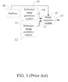
- FIG. 1 is a conventional apparatus 1 for drawing a water surface image.
- the apparatus 1 comprises a database 10 , a reflection image generation module 11 , a refraction image generation module 12 , and an image mergence module 13 .
- the database 10 stores a water wave map 16 .
- the reflection image generation module 11 and the refraction image generation module 12 respectively generate a reflection image 14 and a refraction image 15 according to a fixed water height, wherein the fixed water height is the surface when the water is calm.
- the image mergence module 13 utilizes the equation (1) to merge the water wave map 16 , the reflection image 14 , and the reflection image 15 into a water surface image 17 .
- the conventional apparatus 1 does not consider the actual water surface height when the reflection image 14 and the refraction image 15 are generated. More particularly, the conventional apparatus 1 sets the water surface height, y axis, is always 0 to generate the reflection image 14 and the refraction image 15 . However, it only occurs when the water is calm. If the water has big waves, the errors of displaying the image of the water surface occur. As the FIG. 2 shows, bubbles 21 , supposed to be around a rock 20 , is not around the rock 20 and a refraction 22 of the part of rock 20 under the water apparently breaks off the position of the rock 20 . Another error as shown in FIG. 3 is that the conventional apparatus 1 erroneously determines the refraction as the reflection 30 . The errors shown in FIG. 2 and FIG. 3 occur because the reflection image and the refraction image are generated according to the fixed water height, but not the actual water height.
- the apparatus comprises a map mergence module, a first generation module, a coordinate generation module, and an image generation module.
- the map mergence module is used to merge a plurality of water wave maps into a merged water wave map.
- the first generation module is used to generate a plurality of first water grids in a visible range of each of the water wave maps and generate a plurality of second water grids in the visible range of the merged waves map, wherein each of the first water grids and the second water grids has a two-dimension coordinate.
- the coordinate generation module is used to generate a plurality of corresponding third-dimension coordinates according to the two-dimension coordinates of the first water grids.
- the image generation module is used to generate the water surface according to the corresponding third-dimension coordinates and the two-dimension coordinates of the second water grids.
- Another objective of this invention is to provide a method of drawing a water surface.
- the method comprises the following steps: merging a plurality of water wave maps into a merged water wave map; generating a plurality of first water grids in a visible range of each of the water wave maps, wherein each of the first water grids has a two-dimension coordinate; generating a plurality of second water grids in the visible range of the merged waves map, wherein each of the second water grids has a two-dimension coordinate; generating a plurality of corresponding third-dimension coordinates according to the two-dimension coordinates of the first water grids; and generating the water surface according to the corresponding third-dimension coordinates and the two-dimension coordinates of the second water grids.
- Yet a further objective of the invention is to provide a computer readable medium for storing a computer program.
- the computer program makes an apparatus to execute a method for drawing a water surface image.
- the method comprises the following steps: merging a plurality of water wave maps into a merged water wave map; generating a plurality of first water grids in a visible range of each of the water wave maps, wherein each of the first water grids has a two-dimension coordinate; generating a plurality of second water grids in the visible range of the merged waves map, wherein each of the second eater grids has a two-dimension coordinate; generating a plurality of corresponding third-dimension coordinates according to the two-dimension coordinates of the first water grids; and generating the water surface according to the corresponding third-dimension coordinates and the two-dimension coordinates of the second water grids.
- the invention is capable of dynamically obtaining the information of the actual water surface height and generating a water surface image according to the information of the actual water surface height. If there are objects under or above the water surface, such as rocks, boats, or whales, the invention further generates the reflection image and the refraction image thereof according to the information of the actual water surface height.
- the reflection image, the refraction image, and the water surface image are all merged to create a more realistic 3D picture in order to increase the value of the 3D animation industry.
- FIG. 1 is a schematic diagram of a conventional apparatus for drawing a water surface.
- FIG. 2 is a 3D picture drawn with the conventional apparatus.
- FIG. 3 is another 3D picture drawn with the conventional apparatus.
- FIG. 4 is a schematic diagram of a first embodiment of the invention.
- FIG. 5 is an oscillogram of sine waves.
- FIG. 6 is a schematic diagram of a water surface in view of human eyes.
- FIG. 7 is a flow chart of a second embodiment of the invention.
- FIG. 8 is a flow chart of step of generating the water grids in the second embodiment.
- FIG. 9 is a flow chart of a third embodiment of the invention.
- FIG. 10 is a flow chart of the step of generating the water grids in the third embodiment.
- FIG. 11 is a 3D picture drawn with the invention.
- FIG. 12 is another 3D picture drawn with the invention.
- FIG. 4 is a schematic diagram of an apparatus 4 for drawing a water surface.
- the apparatus 4 comprises a map mergence module 400 , a first generation module 401 , a coordinate generation module 402 , and an image generation module 403 .
- the map mergence module 400 receives a plurality of water wave maps 404 , wherein the water wave maps 404 are pre-generated.
- Most of the water wave maps 404 in the art, generated by a CPU, are sine wave maps, cosine wave maps, and/or fast Fouier transform wave maps. If the water wave maps 404 are the sine wave maps, simply one of the water wave maps 404 used to generate the water waves is dull. As shown in FIG.
- sine waves 500 and 501 are carried in the different water wave maps 404 .
- the map mergence module 400 is used to merge the water wave maps 404 into a merged water wave map 405 , wherein the merged water wave map 405 is a 2D map.
- the first generation module 401 converts the actual water surface 607 into a rectangle grid map 608 . More particularly, the apexes 609 , 610 , 611 , and 612 of the rectangle grid map 608 correspond to the apexes 603 , 604 , 605 , and 606 , respectively.
- the rectangle grid map 608 comprises a lot of grids each of which has a two-dimension coordinate, wherein the two-dimension coordinate corresponds to the coordinate of the water surface image in x-axis and z-axis.
- the first generation module 401 comprises a retrieval module 408 and a grid generation module 409 .
- the retrieval module 408 generates four first reference points 410 on the boundary of the actual water surface 607 of each of the water wave maps 404 .
- the first reference points 410 are the apexes of the actual water surface 607 , i.e., the apexes 603 , 604 , 605 , and 606 in FIG. 6 .
- the first reference points 410 are transmitted to the grid generation module 409 .
- the retrieval module 408 also generates four second reference points 411 on the boundary of the actual water surface 607 of the merged water wave map 405 .
- the second reference points 411 are the apexes of actual water surface 607 , i.e., the apexes 603 , 604 , 605 , and 606 in FIG. 6 . Then, the second reference points 411 are transmitted to the grid generation module 409 as well.
- the retrieval module 408 is used to define the actual water surface 607 on the water wave maps 404 and the merged water wave map 405 respectively and retrieve four apexes from the actual water surface 607 of each map.
- the grid generation module 409 converts the actual water surface 607 of the water wave maps 404 and the merged water wave map 405 into the grid maps 608 .
- the grid generation module 409 uses a pixel shader to generate the first water grids 406 in the corresponding rectangles, as the grids in the grid map 608 , according to the first reference points 410 , wherein each of the first water grids 406 has a two-dimension coordinate in x-axis and z-axis.
- the grid generation module 409 generates the second water grids 407 in the corresponding rectangle, as the grids in the grid map 608 , according to the second reference points 411 , wherein each of the second water grids 407 has a two-dimension coordinate in x-axis and z-axis.
- the coordinate generation module 402 According to the two-dimension coordinate of each of the first water grids 406 , the coordinate generation module 402 generates a third dimension coordinate 412 for each of the first water grids 406 based on the following equation:
- H W is the third dimension coordinate in y-axis, i.e., the actual water surface height with reference to the water wave
- wave i is the corresponding water wave map
- V pos .xz is the two-dimension coordinate of the first water grids 406
- scale i is a pre-determined constant, wherein the pre-determined constant scale i is defined by users to control the frequencies of ripples.
- the objects in the water are reflected and/or refracted by the water.
- the coordinate generation module 402 generates a third-dimension world coordinate 414 indicating a height difference between vertexes of the objects and the actual water surface height according to two-dimension world coordinates 413 of the vertexes, wherein the two-dimension world coordinates 413 are converted by a vertex shader.
- the image generation module 403 generates a water surface based on the vertex shader according to the two-dimension coordinate of the second water grids 407 and the third dimension coordinate 412 . And the image generation module 403 further determines the vertexes of the objects are under or above the actual water surface according to the two-dimension world coordinates 413 , height coordinates of the vertexes, and the third-dimension world coordinates 414 , wherein the height coordinates are converted by the vertex shader. After that, the image generation module 403 further generates a reflection image and a refraction image for the objects. Finally, with the usage of the pixel shader, the image generation module 403 merges the water surface, the reflection image, and the refraction image into a water surface image 415 which shows light changes.
- FIG. 7 is a method for drawing a water surface.
- step 700 is executed to receive a plurality of water wave maps, wherein the water wave maps are pre-generated.
- Step 701 is then executed to merge the water wave maps into a merged water wave map which approximates real water waves, wherein the merged water wave map is a 2D map.
- Steps 702 and 703 are executed to generate the first water grids and the second water grids respectively. More particularly, as shown in FIG. 8 , step 702 can be divided into the following steps.
- Step 800 is first executed to generate four first reference points on the boundary of the actual water surface of each of the water wave maps.
- the first reference points are the apexes of the actual water surface, i.e., the apexes 603 , 604 , 605 , and 606 in FIG. 6 .
- step 801 is executed to use a pixel shader to generate the first water grids, as the grids in the grid map 608 , according to the first reference points.
- step 801 is to convert the actual water surface of the water wave maps into grid maps.
- step 703 is similar to step 702 to generate the second reference points, and then to generate the second water grids, as the grids of the grid map 608 , according to the second reference points.
- the second reference points are the apexes of the actual water surface of the merged water wave map, such as the apexes 603 , 604 , 605 , and 606 in FIG. 6 .
- Each of the second water grids has a two-dimension coordinate in x-axis and the z-axis.
- step 704 is executed to generate a third dimension coordinate for each of the first water grids based on the following equation:
- step 705 is executed to generate a third-dimension world coordinate indicating a height difference between vertexes of the objects and the actual water surface height according to two-dimension world coordinates of the vertexes, wherein the two-dimension world coordinates are converted by a vertex shader.
- step 706 is executed to generate a water surface according to the two-dimension coordinate of the second water grids and the third dimension coordinate of each of the first water grids.
- step 707 is executed to generate the reflection image and the refraction image according to the two-dimension world coordinates, the third-dimension world coordinates, and height coordinates of the vertexes, wherein the height coordinates are converted by the vertex shader.
- step 708 is executed to generate the water surface image which shows light changes according to the water surface, the reflection image, and the refraction image.
- the method of the second embodiment is able to execute of all the operations in the first embodiment.
- Those skilled in the art can straightforwardly realize how the second embodiment performs these operations and functions based on the above descriptions of the first embodiment, and thus no unnecessary detail is given.
- FIG. 9 is a method for drawing a water surface applied to the apparatus 4 .
- the method is executed by a computer program which is stored in a computer readable medium.
- the computer program has code for the map mergence module 400 to receive the water wave maps.
- the computer program has code for the map mergence module 400 to merge the water wave maps into the merged water wave map.
- step 902 and 903 are executed in which the computer program has code for the first generation module 401 to generate the first water grids and the second water grids, respectively.
- the computer program has code to execute the following steps shown in FIG. 10 .
- step 1000 the computer program has code for the retrieval module 408 to generate the four fist reference points on the boundary of the actual water surface 607 of each of the water wave maps.
- step 1001 is executed in which the computer program has code for the grid generation module 409 to use the pixel shader to generate the first water grids according to the first reference points.
- Each of the first water grids has a two-dimension coordinate in x-axis and the z-axis.
- step 903 similar to step 902 , the computer program has code for the retrieval module 408 to generate the four the second reference points, and the computer program has code for the grid generation module 409 to generate the second water grids according to the second reference points.
- Each of the second water grids has a two-dimension coordinate in x-axis and the z-axis.
- step 904 us executed in which the computer program has code for the coordinate generation module 402 to generate a third dimension coordinate for each of the first water grids based on the following equation:
- step 905 is executed in which the computer program has code for the coordinate generation module 402 to generate the third-dimension world coordinate indicating a height difference between vertexes of the objects and the actual water surface height according to the two-dimension world coordinates of the vertexes.
- step 906 is executed in which the computer program has code for the image generation module 403 to generate the water surface according to the two-dimension coordinate of the second water grids and the third dimension coordinate of each of the first water grids.
- step 907 is executed in which the computer program has code for the image generation module 403 to generate the reflection image and the refraction image according to the two-dimension world coordinates, the third-dimension world coordinate, and the height coordinates of the vertexes.
- step 908 is executed in which the computer program has code for the image generation module 403 to generate the water surface image 415 which shows light changes according to the water surface, the reflection image, and the refraction image.
- the method of the third embodiment is able to execute of all the operations in the first embodiment.
- Those skilled in the art can straightforwardly realize how the third embodiment performs these operations and functions based on the above descriptions of the first embodiment, and thus no unnecessary detail is given.
- the computer readable medium can be a floppy disk a hard disk, an optical disk, a flash disk, a tape, a database accessible from a network or a storage medium with the same functionality that can be easily thought by people skilled in the art.
- the invention can dynamically obtain the information of the actual water surface height and generate the water surface image according to the information of the actual water surface height.
- the invention further generates the reflection image and the refraction image according to the information of the actual water surface height and merges the reflection image, the refraction image, and the water surface image.
- the present invention makes the bubble in the right position, and makes the refraction correctly shown.
Abstract
Description
C result =F(θ)*C reflect+(1−F(θ))*C refract (1)
wherein Cresult is the color of the water surface, Creflect and Crefract are the reflection color and the refraction color respectively, and F(θ) is Fresnel coefficient. Generally speaking, the reflection can be divided into two parts: the environment reflection Cenvironment and the object reflection Clocalreflect. They can be represented by the following equation;
C reflect =C environment +C localreflect (2)
Cenvironment and Clocalreflect are mapped on the water surface via reflection vectors and projection vectors. To further show the change of the depth of the water, the refraction colors of the object in the water also need considering. The following equation can be used:
C refract =e −f(y) *C objectcolor+(1−e −f(y))*C watercolor (3)
wherein Cobjectcolor is the original color of the object, Cwatercolor is the color of the object in the water, and e−f(y) is a ratio coefficient for mixing the two colors.
wherein HW is the third dimension coordinate in y-axis, i.e., the actual water surface height with reference to the water wave, wavei is the corresponding water wave map, Vpos.xz is the two-dimension coordinate of the
Claims (22)
Applications Claiming Priority (3)
| Application Number | Priority Date | Filing Date | Title |
|---|---|---|---|
| TW095147440 | 2006-12-18 | ||
| TW95147440A | 2006-12-18 | ||
| TW095147440A TWI353559B (en) | 2006-12-18 | 2006-12-18 | Apparatus, method, application program and compute |
Publications (2)
| Publication Number | Publication Date |
|---|---|
| US20080143713A1 US20080143713A1 (en) | 2008-06-19 |
| US7800612B2 true US7800612B2 (en) | 2010-09-21 |
Family
ID=39526566
Family Applications (1)
| Application Number | Title | Priority Date | Filing Date |
|---|---|---|---|
| US11/683,525 Active 2029-03-24 US7800612B2 (en) | 2006-12-18 | 2007-03-08 | Apparatus, method, and computer readable medium thereof for drawing 3D water surface according to a real water surface height |
Country Status (4)
| Country | Link |
|---|---|
| US (1) | US7800612B2 (en) |
| JP (1) | JP2008152747A (en) |
| KR (1) | KR100856146B1 (en) |
| TW (1) | TWI353559B (en) |
Cited By (2)
| Publication number | Priority date | Publication date | Assignee | Title |
|---|---|---|---|---|
| US20090278852A1 (en) * | 2008-05-09 | 2009-11-12 | Production Resource Group L.L.C | Control of 3D objects in a light displaying device |
| US8878856B1 (en) * | 2010-06-29 | 2014-11-04 | Nvidia Corporation | System, method, and computer program product for depicting a body of water utilizing a height field and particles |
Families Citing this family (11)
| Publication number | Priority date | Publication date | Assignee | Title |
|---|---|---|---|---|
| US9123183B1 (en) | 2011-10-30 | 2015-09-01 | Lockheed Martin Corporation | Multi-layer digital elevation model |
| US9147283B1 (en) * | 2011-10-30 | 2015-09-29 | Lockhead Martin Corporation | Water surface visualization during a simulation |
| CN102592297B (en) * | 2011-12-27 | 2015-01-07 | Tcl集团股份有限公司 | Real-time water wave texture processing method based on 2D (Two-dimensional) grid |
| US9019309B2 (en) * | 2012-06-07 | 2015-04-28 | Apple Inc. | Adaptive image manipulation |
| CN103745491B (en) * | 2013-12-27 | 2017-03-15 | 江苏如意通动漫产业有限公司 | Chondroskeleton animation producing method |
| CN105608727B (en) * | 2016-03-01 | 2018-08-10 | 中国科学院计算技术研究所 | A kind of offshore of data-driven is surged animation synthesizing method and system |
| CN106934093B (en) * | 2017-01-17 | 2019-05-21 | 南京大学 | Simulate the Trple grid multi-level finite element modeling method of THREE DIMENSIONAL GROUNDWATER FLOW movement |
| CN108830779A (en) * | 2017-11-13 | 2018-11-16 | 哈尔滨安天科技股份有限公司 | Processing method, device, electronic equipment and the storage medium of three-dimensional modeling data |
| US11010963B2 (en) * | 2018-04-16 | 2021-05-18 | Nvidia Corporation | Realism of scenes involving water surfaces during rendering |
| CN112017227A (en) * | 2020-08-27 | 2020-12-01 | 上海交通建设总承包有限公司 | Method for hybrid visualization of terrain model and tidal data generated by point cloud fusion |
| CN112504182B (en) * | 2021-01-08 | 2022-06-10 | 浙江龙头机械有限公司 | Alloy casting detection device utilizing water level change |
Citations (6)
| Publication number | Priority date | Publication date | Assignee | Title |
|---|---|---|---|---|
| US5537641A (en) | 1993-11-24 | 1996-07-16 | University Of Central Florida | 3D realtime fluid animation by Navier-Stokes equations |
| US6747649B1 (en) * | 2002-03-19 | 2004-06-08 | Aechelon Technology, Inc. | Terrain rendering in a three-dimensional environment |
| US20050219249A1 (en) * | 2003-12-31 | 2005-10-06 | Feng Xie | Integrating particle rendering and three-dimensional geometry rendering |
| US6985148B2 (en) | 2001-12-13 | 2006-01-10 | Microsoft Corporation | Interactive water effects using texture coordinate shifting |
| US7038694B1 (en) * | 2002-03-11 | 2006-05-02 | Microsoft Corporation | Automatic scenery object generation |
| US20080068386A1 (en) * | 2006-09-14 | 2008-03-20 | Microsoft Corporation | Real-Time Rendering of Realistic Rain |
Family Cites Families (1)
| Publication number | Priority date | Publication date | Assignee | Title |
|---|---|---|---|---|
| JP3549871B2 (en) * | 2001-07-27 | 2004-08-04 | 株式会社ソニー・コンピュータエンタテインメント | Drawing processing apparatus and method, recording medium storing drawing processing program, drawing processing program |
-
2006
- 2006-12-18 TW TW095147440A patent/TWI353559B/en active
-
2007
- 2007-03-08 US US11/683,525 patent/US7800612B2/en active Active
- 2007-04-03 JP JP2007097074A patent/JP2008152747A/en active Pending
- 2007-04-11 KR KR1020070035384A patent/KR100856146B1/en active IP Right Grant
Patent Citations (7)
| Publication number | Priority date | Publication date | Assignee | Title |
|---|---|---|---|---|
| US5537641A (en) | 1993-11-24 | 1996-07-16 | University Of Central Florida | 3D realtime fluid animation by Navier-Stokes equations |
| US6985148B2 (en) | 2001-12-13 | 2006-01-10 | Microsoft Corporation | Interactive water effects using texture coordinate shifting |
| US7050058B2 (en) | 2001-12-13 | 2006-05-23 | Microsoft Corporation | Interactive water effects using texture coordinate shifting |
| US7038694B1 (en) * | 2002-03-11 | 2006-05-02 | Microsoft Corporation | Automatic scenery object generation |
| US6747649B1 (en) * | 2002-03-19 | 2004-06-08 | Aechelon Technology, Inc. | Terrain rendering in a three-dimensional environment |
| US20050219249A1 (en) * | 2003-12-31 | 2005-10-06 | Feng Xie | Integrating particle rendering and three-dimensional geometry rendering |
| US20080068386A1 (en) * | 2006-09-14 | 2008-03-20 | Microsoft Corporation | Real-Time Rendering of Realistic Rain |
Non-Patent Citations (3)
| Title |
|---|
| Enright et al. "Animation and Rendering of Complex Water Surfaces", published 2002-2003. * |
| Langer et al. "A Spectral-particle hybrid method for rendering faling snow". Published 2004. * |
| Yann Lombard "realistic natural Effect Rendering water", Posted Sep. 7, 2004. * |
Cited By (2)
| Publication number | Priority date | Publication date | Assignee | Title |
|---|---|---|---|---|
| US20090278852A1 (en) * | 2008-05-09 | 2009-11-12 | Production Resource Group L.L.C | Control of 3D objects in a light displaying device |
| US8878856B1 (en) * | 2010-06-29 | 2014-11-04 | Nvidia Corporation | System, method, and computer program product for depicting a body of water utilizing a height field and particles |
Also Published As
| Publication number | Publication date |
|---|---|
| TWI353559B (en) | 2011-12-01 |
| TW200828172A (en) | 2008-07-01 |
| KR20080056617A (en) | 2008-06-23 |
| JP2008152747A (en) | 2008-07-03 |
| KR100856146B1 (en) | 2008-09-03 |
| US20080143713A1 (en) | 2008-06-19 |
Similar Documents
| Publication | Publication Date | Title |
|---|---|---|
| US7800612B2 (en) | Apparatus, method, and computer readable medium thereof for drawing 3D water surface according to a real water surface height | |
| US10885699B2 (en) | Rendering of soft shadows | |
| US8144147B2 (en) | Hierarchical bounding of displaced parametric surfaces | |
| US8896602B2 (en) | Apparatus and method for finding visible points in a point cloud | |
| US11030794B2 (en) | Importance sampling for determining a light map | |
| Soler et al. | Fast calculation of soft shadow textures using convolution | |
| US20040181382A1 (en) | Visualizing the surface of a liquid | |
| KR100738500B1 (en) | Method for bi-layered displacement mapping and protruded displacement mapping | |
| US20130127824A1 (en) | Object Selection in Stereo Image Pairs | |
| US20100302279A1 (en) | Generating voronoi treemaps | |
| US20100085359A1 (en) | Surface normal reconstruction from a single image | |
| CN112396684A (en) | Ray tracing method, ray tracing device and machine-readable storage medium | |
| US7586494B2 (en) | Surface detail rendering using leap textures | |
| US8400445B2 (en) | Image processing program and image processing apparatus | |
| US20040169652A1 (en) | System and computer-implemented method for modeling the three-dimensional shape of an object by shading of a two-dimensional image of the object | |
| US6518964B1 (en) | Apparatus, system, and method for simplifying annotations on a geometric surface | |
| JPH06215150A (en) | Three-dimensional image display device | |
| US8379026B2 (en) | Multiresolution ray intersection | |
| US20160163090A1 (en) | Computing device and method for simulating process of scanning drawing of object | |
| CA2282240C (en) | System and computer-implemented method for modeling the three-dimensional shape of an object by shading of a two-dimensional image of the object | |
| Fuhrmann | Volume data generation from triangle meshes using the signed distance function | |
| Akatürk | Modeling 3D objects with free-form surfaces using 2D sketches | |
| Du | Metaball graphics package | |
| Drury et al. | Method for Displaying Intersections and Expansions of Three Dimensional Volumes |
Legal Events
| Date | Code | Title | Description |
|---|---|---|---|
| AS | Assignment |
Owner name: INSTITUTE FOR INFORMATION INDUSTRY, TAIWAN Free format text: ASSIGNMENT OF ASSIGNORS INTEREST;ASSIGNORS:CHIU, YUNG-FENG;CHANG, CHUN-FA;CHENG, YU-JUNG;REEL/FRAME:018985/0520;SIGNING DATES FROM 20070125 TO 20070128 Owner name: INSTITUTE FOR INFORMATION INDUSTRY, TAIWAN Free format text: ASSIGNMENT OF ASSIGNORS INTEREST;ASSIGNORS:CHIU, YUNG-FENG;CHANG, CHUN-FA;CHENG, YU-JUNG;SIGNING DATES FROM 20070125 TO 20070128;REEL/FRAME:018985/0520 |
|
| STCF | Information on status: patent grant |
Free format text: PATENTED CASE |
|
| FPAY | Fee payment |
Year of fee payment: 4 |
|
| MAFP | Maintenance fee payment |
Free format text: PAYMENT OF MAINTENANCE FEE, 8TH YEAR, LARGE ENTITY (ORIGINAL EVENT CODE: M1552) Year of fee payment: 8 |
|
| MAFP | Maintenance fee payment |
Free format text: PAYMENT OF MAINTENANCE FEE, 12TH YEAR, LARGE ENTITY (ORIGINAL EVENT CODE: M1553); ENTITY STATUS OF PATENT OWNER: LARGE ENTITY Year of fee payment: 12 |