US7794159B2 - Sealed beam coupler for an isolated environment - Google Patents
Sealed beam coupler for an isolated environment Download PDFInfo
- Publication number
- US7794159B2 US7794159B2 US12/396,536 US39653609A US7794159B2 US 7794159 B2 US7794159 B2 US 7794159B2 US 39653609 A US39653609 A US 39653609A US 7794159 B2 US7794159 B2 US 7794159B2
- Authority
- US
- United States
- Prior art keywords
- seal
- housing
- section
- assembly
- collimator unit
- Prior art date
- Legal status (The legal status is an assumption and is not a legal conclusion. Google has not performed a legal analysis and makes no representation as to the accuracy of the status listed.)
- Expired - Fee Related
Links
Images


Classifications
-
- G—PHYSICS
- G02—OPTICS
- G02B—OPTICAL ELEMENTS, SYSTEMS OR APPARATUS
- G02B6/00—Light guides; Structural details of arrangements comprising light guides and other optical elements, e.g. couplings
- G02B6/24—Coupling light guides
- G02B6/26—Optical coupling means
- G02B6/32—Optical coupling means having lens focusing means positioned between opposed fibre ends
-
- G—PHYSICS
- G02—OPTICS
- G02B—OPTICAL ELEMENTS, SYSTEMS OR APPARATUS
- G02B6/00—Light guides; Structural details of arrangements comprising light guides and other optical elements, e.g. couplings
- G02B6/24—Coupling light guides
- G02B6/36—Mechanical coupling means
- G02B6/38—Mechanical coupling means having fibre to fibre mating means
- G02B6/3807—Dismountable connectors, i.e. comprising plugs
- G02B6/381—Dismountable connectors, i.e. comprising plugs of the ferrule type, e.g. fibre ends embedded in ferrules, connecting a pair of fibres
- G02B6/3814—Dismountable connectors, i.e. comprising plugs of the ferrule type, e.g. fibre ends embedded in ferrules, connecting a pair of fibres with cooling or heat dissipation means
-
- G—PHYSICS
- G02—OPTICS
- G02B—OPTICAL ELEMENTS, SYSTEMS OR APPARATUS
- G02B6/00—Light guides; Structural details of arrangements comprising light guides and other optical elements, e.g. couplings
- G02B6/24—Coupling light guides
- G02B6/36—Mechanical coupling means
- G02B6/38—Mechanical coupling means having fibre to fibre mating means
- G02B6/3807—Dismountable connectors, i.e. comprising plugs
- G02B6/381—Dismountable connectors, i.e. comprising plugs of the ferrule type, e.g. fibre ends embedded in ferrules, connecting a pair of fibres
- G02B6/3813—Dismountable connectors, i.e. comprising plugs of the ferrule type, e.g. fibre ends embedded in ferrules, connecting a pair of fibres for transmission of high energy beam
-
- G—PHYSICS
- G02—OPTICS
- G02B—OPTICAL ELEMENTS, SYSTEMS OR APPARATUS
- G02B6/00—Light guides; Structural details of arrangements comprising light guides and other optical elements, e.g. couplings
- G02B6/24—Coupling light guides
- G02B6/42—Coupling light guides with opto-electronic elements
- G02B6/4201—Packages, e.g. shape, construction, internal or external details
- G02B6/4219—Mechanical fixtures for holding or positioning the elements relative to each other in the couplings; Alignment methods for the elements, e.g. measuring or observing methods especially used therefor
- G02B6/422—Active alignment, i.e. moving the elements in response to the detected degree of coupling or position of the elements
- G02B6/4226—Positioning means for moving the elements into alignment, e.g. alignment screws, deformation of the mount
-
- G—PHYSICS
- G02—OPTICS
- G02B—OPTICAL ELEMENTS, SYSTEMS OR APPARATUS
- G02B6/00—Light guides; Structural details of arrangements comprising light guides and other optical elements, e.g. couplings
- G02B6/24—Coupling light guides
- G02B6/42—Coupling light guides with opto-electronic elements
- G02B6/4201—Packages, e.g. shape, construction, internal or external details
- G02B6/4248—Feed-through connections for the hermetical passage of fibres through a package wall
Definitions
- the present patent document relates generally to lasers and more specifically to a beam coupler with a sealed housing configured for use in an isolated environment that may contain hazardous and/or contaminated materials.
- Beam couplers are often used in a health-hazardous environment, such as radiation-contaminated facilities.
- the procedure established for its repairing is time-consuming and complicated.
- the coupler assembly includes preferably, but not necessarily, a tubular housing having a sidewall with an interior surface, an exterior surface, a first end and a second end.
- a first seal extends from the interior surface of the tubular housing and divides the tubular housing into a first section and a second section. Consequently, the first section and second section are environmentally isolated from one another.
- An input collimator unit received within the first end of the sidewall of the tubular housing and into the first section and is releasably coupled thereto.
- An output collimator unit received within the second end of the sidewall of the tubular housing and into the second section and is also releasably coupled thereto.
- a flange extends from the exterior surface of the sidewall of the tubular housing and is configured and arranged to mount to an aperture on an exterior wall of the isolated environment.
- the output collimator unit When mounted thereto, the output collimator unit is within the interior portion of the isolated environment and the input collimator unit is outside of the isolated environment.
- the beam coupler of the present invention prevents excursion of material through the coupler from the isolated environment that contains hazardous or contaminated materials. Furthermore, the beam coupler allows alignment from outside the contaminated area.
- FIG. 1 is a front perspective view of the preferred embodiment of the coupler assembly of the present invention
- FIG. 2 is a side cross-section view through line II-II of FIG. 1 ;
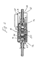
- FIG. 3 is a cross section of mid-portion of the coupler assembly of FIG. 2 ;
- FIG. 4 is a close-up view of the mid-portion of the coupler assembly of FIG. 2 ;
- FIG. 5 is a rear face view of the input collimator unit of the coupler assembly.
- FIG. 6 is a sectional view of the input collimator unit of the coupler assembly.
- the beam coupler 10 includes input and output collimator modules 12 , 14 respectively, which can be individually mounted/dismounted to and from an outer housing 16 .
- housing 16 includes a peripheral flange 18 which is mounted to a partition on the contaminated environment area so that output collimator module 14 is located inside the contaminated environment.
- FIG. 2 illustrates one aspect of the present disclosure which relates to a structure reliably shielding the housing or optical cavity in general and, in particular, input collimator unit 12 when output unit 14 is removed from housing 16 by, for example, a robotic arm.
- This is attained by providing a midsection of housing 16 as a compartment configured to receive one or more flat windows 20 made from fused silica and coated with antireflective coating.
- the windows 20 are configured to prevent flow communication of contaminants towards input collimator unit 12 while allowing laser energy to pass through without reflecting or degrading energy source.
- the redundancy of windows 20 provides for an additional safety measure if one of windows 20 is damaged.
- flat windows 20 each have indium-made seals 22 hermetically coupling glass to metal and rubber seal 24 sealing metal to metal, as best seen in FIG. 4B . If one of the windows 20 and the seals 22 , 24 is damaged, the other, redundant window 20 with respective seals 22 and 24 can fully isolate the input collimator from the hazardous environment. Furthermore, the other window 20 allows for replacement of damaged item without penetration of hazardous material into non-hazardous environment, regardless whether the damaged item is located in or outside the hazardous environment.
- the compartment with windows 20 is characterized by a certain pressure.
- beam coupler 10 is used in environment having pressure different from that one inside the compartment. If the outside pressure is too high, for example, the geometry of windows 20 may be distorted. If windows 20 are not flat, obviously the light beam between collimator modules 12 and 14 can be distorted, since the windows would operate as lenses.
- beam coupler 10 has an air-stabilizing means providing communication between the compartment and the environment.
- the air-stabilizing means is a set screw 26 ( FIG. 3 ) that may be adjusted to equalize the pressure.
- the air-stabilizing means may be a valve.
- the output collimator module 16 is enclosed by a shroud 21 ( FIG. 1 ), which is held in place to the flange via tapered pins and magnetic strips to permit easy removal of the shroud therefrom.
- the shroud 21 prevents contaminates from settling on the coupler assembly.
- the shroud includes a number of apertures therethrough.
- a first aperture 28 ( FIG. 2 ) is configured to allow the delivery fiber to extend therethrough with minimal binding.
- the first aperture includes flexible members 30 that hug the delivery fiber and restrict the ability of contaminants to penetrate to the interior of the shroud. However, the flexible members do not form an air-tight seal between the shroud and the delivery fiber.
- the second aperture 39 ( FIG. 2 ) is configured to allow a coolant tube therethrough to deliver coolant fluid to the work site and/or tool.
- a grommet holds the tube in place in the shroud.
- the coolant tube is connected to a quick-release connector, which may have a check-valve.
- the shroud will be under a positive pressure which exceeding atmospheric pressure via the third aperture 32 ( FIG. 2 ).
- the higher inside pressure is an additional safety barrier preventing contaminants from penetrating inside the housing cavity.
- Inert gas pressure is supplied through a hose, which is connected to the shroud through a connector 19 .
- a further feature of the present disclosure includes an X-Y-Z adjustment mechanism provided with a plurality of adjustment screws.
- the adjustment mechanism of this disclosure provides adjustment of only input collimator unit 12 in order to facilitate alignment of the collimator units from the exterior of the contaminated environment, which will be further described below.
- the input collimator unit 12 includes an outer housing 36 with a rear face and a sidewall forming a hollow interior.
- the rear face extends beyond the sidewall forming a lip with a shoulder.
- a fiber bayonet mount is secured to the front face of the outer housing.
- an inner housing 34 is suspended within the interior of the outer housing.
- the inner housing 34 further includes a central cavity with a restricted portion.
- the inner housing also includes a pair of fluid coolant chambers 40 ( FIG. 3 ). These fluid coolant chambers are also space adjacent to the restricted portion of the central cavity, which also includes thinned wall segments to facilitate heat transfer thereto.
- the coolant chambers are in fluid connection to with fluid inlet connectors 42 via a bellows tubing.
- the bellows tubing includes a knurled section, a bellows section and a straight section, which permit the bellows tubing to flex or move as the inner housing is adjusted relative to the outer housing.
- the inner housing 34 includes a detector unit and a lens assembly that are fit into opposite ends of the central cavity until they are seated against the shoulders of the restricted portion of the central cavity and locked in place.
- the inner housing 34 ( FIG. 3 ) includes an outer rim with a concentric ledge formed extending from the sidewall of the inner housing.
- the inner housing is suspended within the outer housing 36 via a number of extension springs 38 , best seen in FIG. 5 .
- four springs 38 are provided.
- One end of each spring is secured via a dowel pin 41 to the inner housing through an aperture through the ledge and rim of the inner housing as shown in FIG. 5 .
- Each dowel pin rests in a recess formed on the front face of the inner housing, opposite the ledge.
- the opposite end of the spring is secured via retaining clip within a slot formed on the interior of the outer housing.
- Each spring may freely extend outwardly or contract into its respective slot. In this manner, the interior housing is held and within the outer housing.
- each adjustment screw 43 is threaded into a bore formed through the outer housing from the rear face thereof.
- An access point is provided on the rear face of the outer housing to each bore, which permits a technician to insert a tool to adjust each adjustment screw 43 .
- Each access point may be further enclosed via a cap to prevent grim and moisture from entering the bore.
- the adjust screws 43 may be threadably extended and retracted from the outer housing. Extending the adjust screws forces them outwardly towards the inner housing where the end of the screw will contact a hardened seat 44 on ledge of the rim of the inner housing.
- the adjust screw causes the tip of the adjust screw to exert an outward force against the ledge of the rim thereby forcing the inner housing to tilt or pivot in that direction as the extension springs are stretched.
- the inner housing and lens assembly contained therein may be finely or minutely adjusted relative to the lens assembly of the opposing output collimator unit. In this manner, the collimator units 12 , 14 may be optically aligned with one another.
- the output collimator unit 14 includes a housing with a front face, rear face and sidewall.
- the rear face extends outwardly beyond the sidewall forming a lip with a shoulder.
- the sidewall further includes two concentric spaced-apart coolant chambers which are interconnected via transfer zone.
- coolant tube 48 Further connecting the coolant chambers together is a coolant tube 48 , which extends out the front face of the housing and terminates in a fluid inlet connector.
- a secondary fluid inlet connector is also provided, which is also in fluid connection with the coolant chambers.
- coolant fluid is circulated through connector, fluid tube, coolant chambers, and fluid connector to regulate the operating temperature of the collimator unit 14 , and specifically lens assembly, within acceptable tolerances.
- the housing is press-fit into a jacket.
- the jacket abuts the shoulder on the lip of the housing and snugly encases the sidewall, thereby also enclosing the coolant chambers.
- a central bore if formed through the rear face to the front face of the housing.
- the central bore includes a restricted portion near the center of the bore, which forms two shoulders at either end thereof where the bore widens.
- the restricted portion of the bore includes thinned wall segments adjacent to coolant chambers to facilitate heat transfer to the fluid coolant.
- the detector holder is press-fit through the rear face of the housing and into the bore until it rests up against the shoulder.
- a fiber bayonet mount is coupled to the rear face of the housing and includes a fiber cavity configured to receive an optical fiber bayonet. The fiber cavity extends through the bayonet mount and is aligned with the detector holder where the end of the fiber is fixed within the central cavity.
- a lens assembly is press-fit through the bore on the front face until it abuts the opposite shoulder of the restricted portion of the bore.
- the lens assembly includes several lenses and gratings configured and arranged to transmit the laser beam therethrough with minimal power loss, diffraction and reflection.
- An air gap lies between the lens assembly and the end of the detector holder through the central cavity and to the end of the fiber.
- the flange 18 includes a number of connectors therethrough for circulating fluid coolant to the output collimator unit 14 and fiber bayonet via a number of fluid hoses. In this manner, fluid coolant is provided to the output collimator unit and fiber bayonet, yet the coolant remains isolated from the contaminated environment.
- an electrical connector 29 ( FIG. 1 ) on the flange 18 , which is connected to the output collimator unit 14 via an extension wire. In this manner, the detector unit of the output collimator unit 14 may be monitored.
- the present invention provides a unique solution to the problem of providing a beam couple that prevents excursion of material through the coupler from an isolated environment that may contain hazardous or contaminated materials.
Landscapes
- Physics & Mathematics (AREA)
- General Physics & Mathematics (AREA)
- Optics & Photonics (AREA)
- Optical Couplings Of Light Guides (AREA)
Abstract
Description
Claims (15)
Priority Applications (1)
| Application Number | Priority Date | Filing Date | Title |
|---|---|---|---|
| US12/396,536 US7794159B2 (en) | 2008-12-31 | 2009-03-03 | Sealed beam coupler for an isolated environment |
Applications Claiming Priority (2)
| Application Number | Priority Date | Filing Date | Title |
|---|---|---|---|
| US12/319,070 US8014641B2 (en) | 2008-12-31 | 2008-12-31 | Beam coupler |
| US12/396,536 US7794159B2 (en) | 2008-12-31 | 2009-03-03 | Sealed beam coupler for an isolated environment |
Related Parent Applications (1)
| Application Number | Title | Priority Date | Filing Date |
|---|---|---|---|
| US12/319,070 Continuation-In-Part US8014641B2 (en) | 2008-12-31 | 2008-12-31 | Beam coupler |
Publications (2)
| Publication Number | Publication Date |
|---|---|
| US20100166366A1 US20100166366A1 (en) | 2010-07-01 |
| US7794159B2 true US7794159B2 (en) | 2010-09-14 |
Family
ID=42285095
Family Applications (1)
| Application Number | Title | Priority Date | Filing Date |
|---|---|---|---|
| US12/396,536 Expired - Fee Related US7794159B2 (en) | 2008-12-31 | 2009-03-03 | Sealed beam coupler for an isolated environment |
Country Status (1)
| Country | Link |
|---|---|
| US (1) | US7794159B2 (en) |
Cited By (2)
| Publication number | Priority date | Publication date | Assignee | Title |
|---|---|---|---|---|
| US20130336616A1 (en) * | 2011-02-16 | 2013-12-19 | Ipg Photonics Corporation | Beam Coupler Alignment System and Method |
| US8652287B2 (en) | 2011-07-07 | 2014-02-18 | Go!Foton Holdings, Inc. | Apparatus and method for positioning an optical device |
Families Citing this family (4)
| Publication number | Priority date | Publication date | Assignee | Title |
|---|---|---|---|---|
| EP2676341B1 (en) * | 2011-02-16 | 2020-06-03 | IPG Photonics Corporation | Beam coupler alignment system and method |
| US10082632B2 (en) * | 2016-04-01 | 2018-09-25 | Ipg Photonics Corporation | Optical fiber cable connector |
| CN109273892B (en) * | 2018-10-26 | 2019-11-12 | 佛山市欧一电器制造厂有限公司 | A kind of coupler of fast assembling-disassembling |
| US12436345B2 (en) * | 2021-12-20 | 2025-10-07 | Intel Corporation | Immersion compatible optical interconnect |
Citations (3)
| Publication number | Priority date | Publication date | Assignee | Title |
|---|---|---|---|---|
| US5039193A (en) * | 1990-04-03 | 1991-08-13 | Focal Technologies Incorporated | Fibre optic single mode rotary joint |
| US20040146252A1 (en) * | 2003-01-29 | 2004-07-29 | Agilent Technologies, Inc. | Optical fibre connector |
| US20060034571A1 (en) * | 2004-08-13 | 2006-02-16 | Fuji Photo Film Co., Ltd. | Laser module with sealed packages having reduced total volume |
-
2009
- 2009-03-03 US US12/396,536 patent/US7794159B2/en not_active Expired - Fee Related
Patent Citations (3)
| Publication number | Priority date | Publication date | Assignee | Title |
|---|---|---|---|---|
| US5039193A (en) * | 1990-04-03 | 1991-08-13 | Focal Technologies Incorporated | Fibre optic single mode rotary joint |
| US20040146252A1 (en) * | 2003-01-29 | 2004-07-29 | Agilent Technologies, Inc. | Optical fibre connector |
| US20060034571A1 (en) * | 2004-08-13 | 2006-02-16 | Fuji Photo Film Co., Ltd. | Laser module with sealed packages having reduced total volume |
Cited By (4)
| Publication number | Priority date | Publication date | Assignee | Title |
|---|---|---|---|---|
| US20130336616A1 (en) * | 2011-02-16 | 2013-12-19 | Ipg Photonics Corporation | Beam Coupler Alignment System and Method |
| US8913861B2 (en) * | 2011-02-16 | 2014-12-16 | Ipg Photonics Corporation | Beam coupler alignment system and method |
| US8652287B2 (en) | 2011-07-07 | 2014-02-18 | Go!Foton Holdings, Inc. | Apparatus and method for positioning an optical device |
| US9014529B2 (en) | 2011-07-07 | 2015-04-21 | Go!Foton Holdings, Inc. | Apparatus and method for positioning an optical device |
Also Published As
| Publication number | Publication date |
|---|---|
| US20100166366A1 (en) | 2010-07-01 |
Similar Documents
| Publication | Publication Date | Title |
|---|---|---|
| US7794159B2 (en) | Sealed beam coupler for an isolated environment | |
| US4889406A (en) | Tilt adjustable optical fibre connectors | |
| US9102563B2 (en) | Environmentally rugged free-space fiber waveguide connector and method of manufacture thereof | |
| US7758255B2 (en) | System and apparatus for fiber optic connector | |
| KR101955130B1 (en) | Precision optical mount for optical devices | |
| CN110221391B (en) | A 10,000-watt adjustable fiber optic connector | |
| US6891608B2 (en) | Aligning a lens with respect to an axis of beam propagation | |
| US7674048B2 (en) | Polarity checking apparatus for multi-fiber connectors | |
| AU621380B2 (en) | Tilt adjustable optical fibre connectors | |
| US7186035B2 (en) | Optical fibre connector | |
| CN113031176B (en) | Optical fiber adjusting mechanism | |
| US8014641B2 (en) | Beam coupler | |
| CN219676343U (en) | Pluggable and wide-redundancy mid-infrared optical fiber coupling output system | |
| WO2017218356A1 (en) | Laser apparatus with exchangeable pump module | |
| CN102118005B (en) | Modular optical resonant chamber of high-power laser | |
| US20240345347A1 (en) | Wavelength-detecting optical fiber indentifier apparatus and method | |
| EP3055722B1 (en) | Receiving device and method for manufacturing such a receiving device | |
| CN120914593B (en) | Excimer laser and lens replacement method thereof | |
| CN206479699U (en) | A kind of back support form large caliber reflecting mirror supporting construction | |
| US20240280762A1 (en) | Connectorization and coupling of optical-fiber collimators | |
| JP2014202891A (en) | Optical connector | |
| CN121325338A (en) | Laser system based on armoured cable output | |
| CN113467001B (en) | A kind of airtight through-cabin optical fiber connector | |
| CN121715715A (en) | Laser cutting head for hot chamber | |
| RU2807289C1 (en) | Contact optical connector with extended isolated beam |
Legal Events
| Date | Code | Title | Description |
|---|---|---|---|
| AS | Assignment |
Owner name: IPG PHOTONICS CORPORATION,MASSACHUSETTS Free format text: ASSIGNMENT OF ASSIGNORS INTEREST;ASSIGNORS:GRAPOV, YURI;JONES, WILLIAM;DIGIANTOMMASO, MICHAEL;REEL/FRAME:022341/0170 Effective date: 20090302 Owner name: IPG PHOTONICS CORPORATION, MASSACHUSETTS Free format text: ASSIGNMENT OF ASSIGNORS INTEREST;ASSIGNORS:GRAPOV, YURI;JONES, WILLIAM;DIGIANTOMMASO, MICHAEL;REEL/FRAME:022341/0170 Effective date: 20090302 |
|
| STCF | Information on status: patent grant |
Free format text: PATENTED CASE |
|
| FEPP | Fee payment procedure |
Free format text: PAYOR NUMBER ASSIGNED (ORIGINAL EVENT CODE: ASPN); ENTITY STATUS OF PATENT OWNER: LARGE ENTITY |
|
| FPAY | Fee payment |
Year of fee payment: 4 |
|
| MAFP | Maintenance fee payment |
Free format text: PAYMENT OF MAINTENANCE FEE, 8TH YEAR, LARGE ENTITY (ORIGINAL EVENT CODE: M1552) Year of fee payment: 8 |
|
| FEPP | Fee payment procedure |
Free format text: MAINTENANCE FEE REMINDER MAILED (ORIGINAL EVENT CODE: REM.); ENTITY STATUS OF PATENT OWNER: LARGE ENTITY |
|
| LAPS | Lapse for failure to pay maintenance fees |
Free format text: PATENT EXPIRED FOR FAILURE TO PAY MAINTENANCE FEES (ORIGINAL EVENT CODE: EXP.); ENTITY STATUS OF PATENT OWNER: LARGE ENTITY |
|
| STCH | Information on status: patent discontinuation |
Free format text: PATENT EXPIRED DUE TO NONPAYMENT OF MAINTENANCE FEES UNDER 37 CFR 1.362 |
|
| FP | Lapsed due to failure to pay maintenance fee |
Effective date: 20220914 |