US7793763B2 - System and method for damping vibrations in elevator cables - Google Patents
System and method for damping vibrations in elevator cables Download PDFInfo
- Publication number
- US7793763B2 US7793763B2 US11/429,243 US42924306A US7793763B2 US 7793763 B2 US7793763 B2 US 7793763B2 US 42924306 A US42924306 A US 42924306A US 7793763 B2 US7793763 B2 US 7793763B2
- Authority
- US
- United States
- Prior art keywords
- cable
- elevator
- damper
- model
- viscous damper
- Prior art date
- Legal status (The legal status is an assumption and is not a legal conclusion. Google has not performed a legal analysis and makes no representation as to the accuracy of the status listed.)
- Expired - Lifetime
Links
- 238000013016 damping Methods 0.000 title claims abstract description 150
- 238000000034 method Methods 0.000 title abstract description 34
- 230000033001 locomotion Effects 0.000 claims description 117
- 230000005284 excitation Effects 0.000 description 59
- 230000004044 response Effects 0.000 description 54
- 238000006073 displacement reaction Methods 0.000 description 47
- 230000000694 effects Effects 0.000 description 43
- 230000008859 change Effects 0.000 description 36
- 230000001133 acceleration Effects 0.000 description 32
- 238000005452 bending Methods 0.000 description 28
- 238000010586 diagram Methods 0.000 description 25
- 239000000725 suspension Substances 0.000 description 24
- 230000007423 decrease Effects 0.000 description 19
- 230000007246 mechanism Effects 0.000 description 18
- 239000007787 solid Substances 0.000 description 17
- 230000014509 gene expression Effects 0.000 description 16
- 230000036461 convulsion Effects 0.000 description 13
- 239000011159 matrix material Substances 0.000 description 9
- 238000013461 design Methods 0.000 description 8
- 238000004904 shortening Methods 0.000 description 8
- 238000013459 approach Methods 0.000 description 7
- 230000036961 partial effect Effects 0.000 description 7
- 238000005381 potential energy Methods 0.000 description 7
- 230000008901 benefit Effects 0.000 description 6
- 239000000523 sample Substances 0.000 description 6
- 230000036962 time dependent Effects 0.000 description 6
- 238000005259 measurement Methods 0.000 description 5
- 239000002245 particle Substances 0.000 description 5
- 238000002474 experimental method Methods 0.000 description 4
- IYLGZMTXKJYONK-ACLXAEORSA-N (12s,15r)-15-hydroxy-11,16-dioxo-15,20-dihydrosenecionan-12-yl acetate Chemical compound O1C(=O)[C@](CC)(O)C[C@@H](C)[C@](C)(OC(C)=O)C(=O)OCC2=CCN3[C@H]2[C@H]1CC3 IYLGZMTXKJYONK-ACLXAEORSA-N 0.000 description 3
- 230000003247 decreasing effect Effects 0.000 description 3
- 230000004069 differentiation Effects 0.000 description 3
- 230000005484 gravity Effects 0.000 description 3
- 230000010354 integration Effects 0.000 description 3
- IYLGZMTXKJYONK-UHFFFAOYSA-N ruwenine Natural products O1C(=O)C(CC)(O)CC(C)C(C)(OC(C)=O)C(=O)OCC2=CCN3C2C1CC3 IYLGZMTXKJYONK-UHFFFAOYSA-N 0.000 description 3
- 230000003068 static effect Effects 0.000 description 3
- 229910000831 Steel Inorganic materials 0.000 description 2
- XAGFODPZIPBFFR-UHFFFAOYSA-N aluminium Chemical compound [Al] XAGFODPZIPBFFR-UHFFFAOYSA-N 0.000 description 2
- 229910052782 aluminium Inorganic materials 0.000 description 2
- 230000005540 biological transmission Effects 0.000 description 2
- 238000004364 calculation method Methods 0.000 description 2
- 238000004891 communication Methods 0.000 description 2
- 230000000368 destabilizing effect Effects 0.000 description 2
- 239000000463 material Substances 0.000 description 2
- 230000003534 oscillatory effect Effects 0.000 description 2
- 230000009291 secondary effect Effects 0.000 description 2
- 238000004088 simulation Methods 0.000 description 2
- 230000000087 stabilizing effect Effects 0.000 description 2
- 239000010959 steel Substances 0.000 description 2
- 238000013519 translation Methods 0.000 description 2
- 229910000669 Chrome steel Inorganic materials 0.000 description 1
- 241000282320 Panthera leo Species 0.000 description 1
- 238000005299 abrasion Methods 0.000 description 1
- 230000001419 dependent effect Effects 0.000 description 1
- 238000009472 formulation Methods 0.000 description 1
- 238000011835 investigation Methods 0.000 description 1
- 238000002955 isolation Methods 0.000 description 1
- 230000000670 limiting effect Effects 0.000 description 1
- 239000000203 mixture Substances 0.000 description 1
- 238000012986 modification Methods 0.000 description 1
- 230000004048 modification Effects 0.000 description 1
- 238000005312 nonlinear dynamic Methods 0.000 description 1
- 238000010606 normalization Methods 0.000 description 1
- 238000005070 sampling Methods 0.000 description 1
- 230000035945 sensitivity Effects 0.000 description 1
- 230000003595 spectral effect Effects 0.000 description 1
- 239000000126 substance Substances 0.000 description 1
- 238000009864 tensile test Methods 0.000 description 1
- 230000001131 transforming effect Effects 0.000 description 1
- 238000010200 validation analysis Methods 0.000 description 1
Images


Classifications
-
- B—PERFORMING OPERATIONS; TRANSPORTING
- B66—HOISTING; LIFTING; HAULING
- B66B—ELEVATORS; ESCALATORS OR MOVING WALKWAYS
- B66B7/00—Other common features of elevators
- B66B7/06—Arrangements of ropes or cables
Definitions
- the present invention relates to control of vibratory energy in translating media and, more particularly, to a system and method of dissipating or damping vibratory energy in translating media, such as elevator cables.
- An object of the invention is to solve at least the above problems and/or disadvantages and to provide at least the advantages described hereinafter.
- the present invention provides a vibration damped elevator system that includes a damper or dampers attached to the elevator cable.
- the damping coefficients of the damper or dampers are chosen to provide optimum dissipation of the vibratory energy in the elevator cable.
- a method of determining the optimum placement of the damper or dampers and their respective damping coefficients is also provided.
- FIGS. 1( a )- 1 ( c ) are schematic diagrams of a vertically traveling hoist cable 110 with a car attached at the lower end for a string model, a pinned-pinned beam model, and a fixed-fixed beam model, respectively;
- FIGS. 2( a )- 2 ( c ) are schematic diagrams showing nonpotential generalized forces acting on the systems of FIGS. 1( a )- 1 ( c ), respectively, at time t;
- FIGS. 3( a )- 3 ( d ) are plots of the upward movement profile of the elevator for l(t), v(t), ⁇ dot over (v) ⁇ (t), and ⁇ umlaut over (v) ⁇ (t), respectively, with the seven regions marked in FIG. 3( d );
- FIGS. 8( a )- 8 ( d ) are plots of the forced responses of the three models of FIGS. 1( a )- 1 ( c ) for y(12,t), y t (12,t), E v (t), and
- FIGS. 9( a )- 9 ( d ) are plots of the forced responses of the models of FIGS. 1( a ) and 1 ( c ) under the low excitation frequencies for y(12,t), y t (12,t), E v (t), and
- FIGS. 10( a )- 10 ( d ) are plots of the forced responses of the models in FIGS. 1( a ) and 1 ( c ) under the high excitation frequencies for y(12,t), y t (12,t), E v (t), and
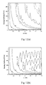
- FIG. 12( a ) is a contour plot of the damping effect for upper boundary excitation when a damper is fixed to the wall or other rigid supporting structure;
- FIG. 12( b ) is a contour plot of the damping effect for upper boundary excitation when a damper is fixed to the elevator car;
- FIG. 12( c ) is a contour plot of the damping effect for lower boundary excitation when a damper is fixed to the wall or other rigid supporting structure;
- FIG. 12( d ) is a contour plot of the damping effect for lower boundary excitation when a damper is fixed to the car;
- FIG. 13 is a schematic of a prototype elevator, in accordance with the present invention.
- FIG. 14 is a schematic of a model elevator, in accordance with the present invention.
- FIGS. 15( a )- 15 ( d ) are plots showing a movement profile of the prototype elevator, where FIG. 15( a ) shows position, 15 ( b ) shows velocity, 15 ( c ) shows acceleration, and 15 ( d ) shows jerk;
- FIG. 16( a ) is a plot showing the prototype tension at the top of the car under the movement profile in FIG. 15 ;
- FIGS. 16( b ) and 16 ( c ) are plots of the tension at the top of the car for the full and half models under the movement profiles corresponding to that for the prototype in FIG. 15 , respectively, with the motor at the top left (solid), bottom left (dashed), top right (dash-dotted), and bottom right (dotted) positions;
- FIG. 17( c ) is a plot of the vibratory energy of the prototype cable (solid) and those predicted by the half models with the motor at the top (dashed) and bottom (dotted) left positions;
- FIG. 18( c ) is a plot of the vibratory energy of the prototype cable (solid) and those predicted by the full models with the motor at the top (dashed) and bottom (dotted) left positions;
- FIG. 19( a ) is a contour plot of the average vibratory energy ratio of the prototype cable during upward movement with its isoline values in percentage labeled;
- FIG. 19( b ) is a contour plot of the final vibratory energy ratio of the prototype cable during upward movement with its isoline values in percentage labeled;
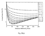
- FIG. 20( a ) is the average vibratory energy ratio of the prototype cable during upward movement from the ground to the top of the building with the first 12 modes as the initial disturbance;
- FIG. 20( b ) is the average vibratory energy ratio of the prototype cable during upward movement from the middle to the top of the building with the first 12 modes as the initial disturbance;
- FIG. 20( c ) is the average vibratory energy ratio of the prototype cable during upward movement from the ground to the middle of the building with the first 12 modes as the initial disturbance;
- FIG. 20( d ) is the final vibratory energy ratio of the prototype cable during upward movement from the ground to the top of the building with the first 12 modes as the initial disturbance;
- FIG. 21( c ) is a plot of the vibratory energy of the prototype cable with the damper mounted 2.5 m above on the car (solid line) and the damper fixed to the wall 2.5 m below the top (dashed line);
- FIG. 22 is a contour plot of the average vibratory energy ratio of the prototype cable during upward movement with its isoline values in J labeled, where the damper is fixed to the wall 2.5 m below the top;
- FIG. 24 is a schematic of an experimental setup used for a scaled elevator
- FIG. 25 is a plot showing the measured tension difference of the band between upward and downward movements with constant velocity as a function of the position of the car, where the dotted line is the original signal, the dashed line is the filtered signal and the solid line is a linearly curve-fitted, filtered signal;
- FIG. 26 is a plot showing the natural damping ratio of the stationary band with varying length, where ( ⁇ ) are experimental data and the line is from the linear curve fit of the data;
- FIGS. 27( a ) and 27 ( b ) are plots showing measured (solid line) and calculated (dashed line) responses of the uncontrolled and controlled stationary bands, respectively, with natural damping;
- FIGS. 28( a )- 28 ( c ) are plots showing measured (solid lines) and prescribed (dashed lines) movement profiles for position, velocity, and acceleration, respectively;
- FIG. 28( d ) is a plot showing calculated tensions using measured (solid line) and prescribed (dashed line) movement profiles
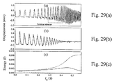
- FIGS. 29( a ) and 29 ( b ) are plots showing measured (solid lines) and calculated (dashed lines) responses of the uncontrolled and controlled bands, respectively;
- FIG. 29( c ) is a plot showing calculated vibratory energies of the uncontrolled band with (solid line) and without (dotted line) natural damping and the controlled band with natural damping (dashed line);
- FIGS. 30( a ) and 30 ( b ) are schematic diagrams of a vibration dampened 1:1 traction elevator system with a rigid and soft suspension, respectively, in which an elevator mounted damper is used for vibration damping, in accordance with the present invention
- FIGS. 31( a ) and 31 ( b ) are schematic diagrams of a vibration dampened 1:1 traction elevator system with a rigid and soft suspension, respectively, in which a movable damper is used for vibration damping, in accordance with the present invention
- FIG. 31( c ) is a schematic diagram of a preferred embodiment of a movable damper, in accordance with the present invention.
- FIGS. 32( a ) and 32 ( b ) are schematic diagrams of a vibration dampened 1:1 traction elevator system with a rigid and soft suspension, respectively, in which the movable damper is moved via an external motor, in accordance with the present invention
- FIGS. 32( c ) and 32 ( d ) are schematic diagrams of a vibration dampened 1:1 traction elevator system with a rigid and soft suspension, respectively, in which the movable damper is moved via a pulley and cable that are driven by the pulley/motor through a transmission, in accordance with the present invention
- FIGS. 32( e ) and 32 ( f ) are schematic diagrams of a vibration dampened 1:1 traction elevator system with a rigid and soft suspension, respectively, in which the movable damper is rigidly attached to the elevator cable and supported by a structure mounted on the car, in accordance with the present invention
- FIGS. 33( a ) and 33 ( b ) are schematic diagrams of a vibration dampened 1:1 traction elevator system with a rigid and soft suspension, respectively, in which a fixed damper is used for vibration damping, in accordance with the present invention
- FIG. 34 is a schematic diagram showing a preferred method of mounting a fixed damper, in accordance with the present invention.
- FIGS. 35( a ) and 35 ( b ) are schematic diagrams of a vibration dampened 2:1 traction elevator system with a rigid and soft suspension, respectively, in accordance with the present invention
- FIGS. 36( a ) and 36 ( b ) are schematic diagrams of a vibration dampened 2:1 traction elevator system with a rigid and soft suspension, respectively, in which movable dampers are used for vibration damping, in accordance with the present invention
- FIGS. 37( a ) and 37 ( b ) are schematic diagrams of a vibration dampened 2:1 traction elevator system with a rigid and soft suspension, respectively, in which fixed dampers are used for vibration damping;
- FIGS. 38( a ) and 38 ( b ) are schematic diagrams of a vibration damped 2:1 traction elevator system with a rigid and soft suspension, respectively, utilizing a single elevator mounted damper, in accordance with the present invention.
- FIG. 39 is a flowchart of a preferred method for determining the optimum damper placement and damping coefficients, in accordance with the present invention.
- the amplitude of the displacement of a translating medium can behave in a different manner depending on the boundary conditions, the amplitude of the velocity and the vibratory energy decrease and increase in general during extension and retraction, respectively.
- the amplitude of the displacement of a cantilever beam decreases during retraction, and that of an elevator cable 110 increases first and then decreases during upward movement, as shown in W. D. Zhu and J. Ni, “Energetics and Stability of Translating Media with an Arbitrarily Varying Length,” ASME Journal of Vibration and Acoustics, Vol. 122, pp. 295-304 (2000) and in W. D. Zhu and G. Y.
- the lateral response of a moving elevator cable 110 subjected to external excitation due to building sway, pulley eccentricity, and guide-rail irregularity will now be discussed.
- the cable 110 is modeled as a vertically translating string and tensioned beams following reference, as described in W. D. Zhu and G. Y. Xu, “Vibration of Elevator cable 110 s with Small Bending Stiffness,” Journal of Sound and Vibration, Vol. 263, pp. 679-699 (2003).
- the displacement at the upper end of the cable 110 and that of the rigid body at the lower end, representing the elevator car 100 are prescribed.
- the vertically translating hoist cable 110 in elevators has no sag and can be modeled as a taut string, as shown in FIG. 1( a ), and tensioned beams with pinned and fixed boundaries, as shown in FIGS. 1( b ) and 1 ( c ), respectively.
- the elevator car 100 is modeled as a rigid body of mass m e attached at the lower end of the cable 110 .
- the car 100 includes a slide mechanism 120 , that allow the car 100 to travel up and down along guide rails (not shown) that are attached to a rigid supporting structure 130 , such as a wall of a building. The suspension of the car 100 against the guide rails is assumed to be rigid.
- a damper 530 movably attached at one end to the cable 110 and movably attached at a second end to the rigid supporting structure 130 .
- the displacement of the upper end of the cable 110 represents external excitation that can arise from building sway and pulley eccentricity.
- the displacement of the lower end of the cable 110 specified by e 2 (t), represents external excitation due to guide-rail irregularity. Since the allowable vibration in elevators is very small, the lateral and longitudinal vibrations of elevator cable 110 can be assumed to be uncoupled and the longitudinal vibration is not considered here.
- the initial displacement and velocity of the cable 110 are given by y(x,0) and y t (x,0), respectively, where 0 ⁇ x ⁇ l(0).
- the governing equation (1) with the time-dependent boundary conditions (5) can be transformed to one with the homogeneous boundary conditions.
- h(x,t) is selected to satisfy the first two equations in (12).
- the function h(x,t) that satisfies (12) or (13) is chosen to be a third polynomial in x:
- h ⁇ ( x , t ) a 0 ⁇ ( t ) + a 1 ⁇ ( t ) ⁇ x l ⁇ ( t ) + a 2 ⁇ ( t ) ⁇ ( x l ⁇ ( t ) ) 2 + a 3 ⁇ ( t ) ⁇ ( x l ⁇ ( t ) ) 3 , ( 14 ) where a 0 (t), a 1 (t), a 2 (t), and a 3 (t) are the unknown coefficients that can depend on time.
- Applying the first two equations in (12) yields the same h(x,t) for the model in FIG. 1( a ) as that for the model in FIG. 1( b ).
- applying (13) to (14) yields
- h ⁇ ( x , t ) ⁇ e 1 ⁇ ( t ) - 3 ⁇ [ e 1 ⁇ ( t ) - e 2 ⁇ ( t ) ] ⁇ ( x l ⁇ ( t ) ) 2 + 2 ⁇ [ e 1 ⁇ ( t ) - e 2 ⁇ ( t ) ] ⁇ ( x l ⁇ ( t ) ) 3 ( 16 ) ⁇ for the model in FIG. 1( c ).
- the partial derivatives of h(x,t) in (10) and (11) can be obtained once h(x,t) is known. For each model in FIG. 1 the solution for u(x,t) is sought first and y(x,t) is obtained subsequently from (8).
- E o [y,t] E g ( t )+ E r ( t )+ E v [y,t], (17)
- E g (t) is the gravitational potential energy
- E r (t) is the kinetic energy associated with the rigid body translation
- E v [y,t] is the energy associated with the lateral vibration.
- E v is an integral functional that depends on y(x,t), as will be seen in (20) and (21), and consequently so do E o .
- the vibratory energy of the cable 110 when it is modeled as a tensioned beam, as shown in FIGS. 1( b ) and 1 ( c ), is
- E v ⁇ [ y , t ] ⁇ 0 l ⁇ ( t ) ⁇ ⁇ v ⁇ d x , ⁇
- ⁇ v 1 2 ⁇ ⁇ ⁇ ⁇ [ y t + v ⁇ ( t ) ⁇ y x ] 2 + T ⁇ ( x , t ) ⁇ y x 2 + EIy xx 2 ⁇ ( 21 ) is the energy density associated with the lateral vibration.
- the rate of change of the energy of the translating cable 110 can be calculated from the control volume and system viewpoints.
- the control volume at time t is defined as the spatial domain 0 ⁇ x ⁇ l(t), formed instantaneously by the translating cable 110 between the two boundaries, and the system concerned consists of the cable 110 particles of fixed identity, occupying the spatial domain 0 ⁇ x ⁇ l(t) at time t.
- the rate of change of the vibratory energy in (20) from the control volume viewpoint is obtained by differentiating (20) using Leibnitz's rule. For instance, for the model in FIG. 1( a ), we have
- the rate of change of the vibratory energy from the control volume viewpoint describes the instantaneous growth and decay of the vibratory energy of the translating cable 110 with variable length, it can characterize the dynamic stability of the cable 110 in each model in FIG. 1 .
- the first term on the right-hand sides of (24)-(26) is negative and positive definite during downward (v(t)>0) and upward (v(t) ⁇ 0) movement of the cable 110 , respectively.
- the second term on the right-hand sides of (24) and (25) is positive and negative definite during downward and upward movement, respectively, competing with the effect of the first term on the right-hand sides of (24) and (25).
- a positive and negative jerk ⁇ umlaut over (v) ⁇ (t) has a stabilizing and destabilizing effect, respectively, as observed from the third term on the right-hand sides of (24) and (25) and the second term on the right-hand side of (26). All the other terms on the right-hand sides of (24)-(25) are sign-indefinite.
- the rate of change of the total mechanical energy from the system viewpoint, as calculated above for each model in FIG. 1 is shown to provide an instantaneous work and energy relation for the system of the cable particles, located in the spatial domain 0 ⁇ x ⁇ l(t) at time t. Because the tension in the cable 110 varies with time, the potential energy associated with the tension is time-dependent.
- the work and energy relation for a system of particles with a time-dependent potential energy states that the rate of change of the total mechanical energy of the system equals the resultant rate of work done by the nonpotential forces plus the partial time derivative of the time-dependent potential energy.
- the nonpotential generalized forces acting on the system in each model in FIG. 1 include forces—such as the axial forces, transverse forces, shear forces, damping force, and distributed external forces—and moments—such as the bending moments in FIG. 2( c )—exerted by the cable 110 segment above the system and by the car 100 at the two ends of the system.
- forces such as the axial forces, transverse forces, shear forces, damping force, and distributed external forces
- moments such as the bending moments in FIG. 2( c )—exerted by the cable 110 segment above the system and by the car 100 at the two ends of the system.
- the standard sign convention for internal forces is used for the tensions, shear forces, and bending moments at the two ends of the system
- the linear theory is used to approximate the axial and transverse forces at the two ends of the system in FIGS. 2( a ) and 2 ( b ).
- the rates of work done by the nonpotential generalized forces in FIG. 2 are the products of the generalized forces and the corresponding generalized velocities, as shown in Tables 1-3, where
- V 1 ⁇ [ y , t ] 1 2 ⁇ ⁇ 0 l ⁇ ( t ) ⁇ T ⁇ ( x , t ) ⁇ y x 2 ⁇ ⁇ d x , the term before the last in (32), (33) and (34) has been shown in Zhu and Ni, “Energetics and Stability of Translating Media with an Arbitrary Varying Length,” ASME Journal of Vibration and Acoustics, Vol. 122, pp. 295-304 (2000), to be its partial time derivative.
- ⁇ x l ⁇ ( t ) is introduced and the time-varying spatial domain [0,l(t)] for x is converted to a fixed domain [0,1] for ⁇ .
- the partial derivatives of u(x,t) with respect to x and t are related to those of û( ⁇ ,t) with respect to ⁇ and t:
- q j (t) are the generalized coordinates
- ⁇ j ( ⁇ ) are the trial functions
- n is the number of included modes.
- the normalized eigenfunctions of the pinned-pinned and fixed-fixed beams with unit length are used as the trial functions for the models in FIGS.
- E v ⁇ ( t ) ⁇ 1 2 ⁇ [ l ⁇ ( t ) ⁇ q . T ⁇ ( t ) ⁇ M ⁇ q . ⁇ ( t ) + l ⁇ ( t ) ⁇ q . T ⁇ ( t ) ⁇ C ⁇ ( t ) ⁇ ⁇ q ⁇ ( t ) + q T ⁇ ( t ) ⁇ S ⁇ ( t ) ⁇ q ⁇ ( t ) ] + ⁇ P T ⁇ ( t ) ⁇ q .
- (8), (39), and (43) in (25) yields the discretized expression of the rate of change of the vibratory energy from the control volume viewpoint for the model in FIG. 1( b ):
- ⁇ tilde over (q) ⁇ j (t) are the generalized coordinates
- ⁇ j (x,t) are the time-dependent trial functions.
- the instantaneous eigenfunctions of a stationary string with variable length l(t) and fixed boundaries are used as the trial functions for the model in FIG. 1( a ).
- the instantaneous eigenfunctions of a stationary beam with variable length l(t) and pinned boundaries are used as the trial functions for the model in FIG.
- ⁇ j ( ⁇ ) are the normalized eigenfunctions of the corresponding string and beam with unit length, as used in the first scheme.
- E v ⁇ ( t ) 1 2 ⁇ [ q ⁇ . T ⁇ ( t ) ⁇ M ⁇ ⁇ ( t ) ⁇ q ⁇ . ⁇ ( t ) + q ⁇ . T ⁇ ( t ) ⁇ C ⁇ ⁇ ( t ) ⁇ q ⁇ ⁇ ( t ) + q ⁇ T ⁇ ( t ) ⁇ S ⁇ ⁇ ( t ) ⁇ ⁇ ⁇ ( t ) ] + ⁇ P ⁇ T ⁇ ( t ) ⁇ q ⁇ .
- E v ⁇ ( t ) 1 2 [ q ⁇ . T ⁇ ( t ) ⁇ M ⁇ ⁇ q ⁇ . ⁇ ( t ) + q ⁇ . T ⁇ ( t ) ⁇ C ⁇ ⁇ ( t ) ⁇ q ⁇ ⁇ ( t ) + q ⁇ T ⁇ ( t ) ⁇ S ⁇ ⁇ ( t ) ⁇ q ⁇ ⁇ ( t ) ] + ⁇ P ⁇ T ⁇ ( t ) ⁇ q ⁇ .
- entries of the gyroscopic matrix associated with a translating medium with constant length are given by the first term in the first equation in (89).
- Gaining mass during extension i.e., v(t)>0
- lose mass during retraction i.e., v(t) ⁇ 0
- the normalization procedure in the second scheme renders the mass matrix ⁇ tilde over (M) ⁇ in (68) a constant matrix. Consequently, the damping effect due to mass variation does not exist and the resulting matrix C in (68) is the skew-symmetric gyroscopic matrix.
- the initial and final lengths of the cable 110 are 171 m and 21 m, respectively.
- the maximum velocity, acceleration, and jerk are 5 m/s, 0.75 m/s 2 , and 0.845 m/s 3 , respectively, and the total travel time is 38 s.
- the fundamental frequencies of the cable 110 with the initial and final lengths are around 0.25 Hz and 2.05 Hz, respectively.
- the rate of change of the vibratory energy for the model in FIG. 1( c ) cannot be calculated from (76) because y xx (0,t) in (26) cannot be determined, but can be calculated from the vibratory energy by using the finite difference method. While the terms involving EIy xxx (0,t) and EIy xxx (l(t),t) in (26) have negligible contributions, those in (26) can have significant contributions as the transverse force at the fixed ends of the beam model in FIG. 1( c ) equals the shear force. In what follows the third scheme is used.
- the convergence of the solution for each model in FIG. 1 is examined by varying the number of included modes. Since the convergence of the model in FIG. 1( b ) is similar to that of the model in FIG. 1( a ), only the results for the models in FIGS. 1( a ) and 1 ( c ) are presented, as shown in FIGS. 5 and 6 , respectively.
- the solution is expressed in (66) with ⁇ j (x,t) replaced with the time-independent trial functions ⁇ j (x).
- the mass matrices that result from the two different types of the trial functions for the beam model are the same, and the differences between the diagonal entries of the stiffness matrices decrease with n, and are less than 2% when n>18 and less than 1% when n>36.
- the forced response of the moving cable 110 converges faster than that of the stationary cable 110 , because the energy increase due to the shortening cable 110 behavior dominates the energy variation due to the forcing terms for the moving cable 110 and the relative bending stiffness of the cable 110 to the tension increases as the length of the cable 110 shortens during upward movement.
- the three models in FIG. 1 yield essentially the same results for the forced response of the elevator cable 110 due to its small bending stiffness.
- the model in FIG. 1( c ) using the untensioned beam eigenfunctions as the trial functions, converges more slowly for the forced response than for the free response.
- the rate of change of the vibratory energy from the control volume viewpoint can characterize the dynamic stability of the cable 110 , and that of the total mechanical energy from the system viewpoint establish an instantaneous work and energy relation.
- the three spatial discretization schemes yield the same results and the third scheme is the most physical approach. While the vibratory energy of the cable 110 can have an oscillatory behavior with the low excitation frequencies, it increases in general with the higher excitation frequencies during upward movement of the elevator.
- excitation sources There are three excitation sources: (1) building sway; (2) pulley eccentricity; and (3) guide-rail irregularity. Excitation can also arise from concentrated and/or distributed external forces that can result from aerodynamic or wind excitation. Theses are included in the formulation, but not considered in the examples.
- the displacement of the upper end of the cable represents external excitation that can arise from building sway and/or pulley eccentricity.
- the displacement of the lower end of the cable represents external excitation due to guide-rail irregularity and/or building sway.
- the excitations considered in the examples can be simplified into two sources: the excitation from the upper end and the excitation from the lower end.
- a damper can be mounted either on the passenger car, on the wall or other rigid supporting structure, or on a small car moving along the guide rail with the cable or relative to the cable, as will be described in more detail below.
- the cases with the damper attached to the passenger car and to the wall are investigated in what follows.
- the damper When mounted on the wall, the damper is preferably installed close to the top of the hoist way, so that the passenger car will not collide with it.
- a damper can be mounted either on the passenger car, on the wall or other rigid supporting structure, or on a small car moving along the guide rail with the cable or relative to the cable, as will be described in more detail below.
- the cases with the damper attached to the passenger car and to the wall are investigated in what follows. When mounted on the wall, the damper is installed close to the top of the hoist way, otherwise the passenger car may collide with it.
- the contour plot of the damping effect for each of the above four cases is obtained by varying the excitation frequency and damping coefficient, where the damping effect is defined as the percentage ratio of the damped average vibratory energy during upward movement of the elevator to the undamped average vibratory energy.
- the average energy is defined as
- E average ⁇ 0 total ⁇ E v ⁇ d t t total .
- FIG. 12( a ) is a contour plot of the damping effect for the upper boundary excitation with the damper fixed to the wall.
- the damper can effectively reduce the vibratory energy.
- a damper with a larger damping coefficient can reduce more vibratory energy.
- An incident wave generated by the upper boundary propagates to the damper and generates a transmitted wave and a reflected wave.
- the damper also dissipates some energy of the incident wave.
- the reflected wave has much more energy than the transmitted wave.
- the reflected wave reflects from the upper boundary and can generate another pair of transmitted and reflected waves when it gets to the damper.
- the transmitted wave reflects from the lower boundary and can generate another pair of transmitted and reflected waves when it gets to the damper.
- FIG. 12( b ) is a contour plot of the damping effect for the upper boundary excitation with the damper fixed to the passenger car.
- the optimal damping coefficient decreases from 1000 to 200 Ns/m when the excitation frequency is increased from 0 to 3 Hz.
- the modal method is used to explain the result in this case.
- the vibration of the cable can be decomposed into a series of instantaneous modes.
- the low frequency excitation from the upper boundary excites more lower modes and the high frequency excitation excites more higher modes. Since the damper is close to the lower boundary, for the lower modes the vibration at the damper's position is relatively small, and a damper with a relatively large damping coefficient will increase the damping force and dissipate more energy.
- FIG. 12( c ) is a contour plot of the damping effect for the lower boundary excitation with the damper fixed to the wall.
- the optimal damping coefficient decreases from 1000 to 200 Ns/m with the increase of the excitation frequency.
- FIG. 12( d ) is a contour plot of the damping effect for the lower boundary excitation with the damper fixed to the elevator car.
- the optimal damping coefficient decreases from 1000 to 200 Ns/m with the increase of the excitation frequency.
- a damper can effectively dissipate the vibratory energy, especially for the higher frequency excitation, up to 90%.
- the damper is more effective for the higher frequency than for the lower frequency. Since the rate of the energy growth is lower for the lower excitation frequency, the shortening cable behavior at the lower frequency excitation is less severe than that for the high frequency excitation.
- the method of designing the optimal damper for the higher excitation frequency is very attractive.
- the damper will be more effective at the lower frequencies. If the excitation comes from the upper boundary, such as the motor, a damper with a large damping coefficient fixed to the wall could be used as a vibration isolator to isolate the source of vibration.
- the prescribed length of the cable at time t p is l p (t p ).
- the prescribed velocity and acceleration of both the cable and car are
- a positive and negative velocity v p (t p ) indicates downward and upward movement of the elevator, respectively.
- the response of the cable 110 with and without the damper 530 is referred to as the controlled and uncontrolled response, respectively.
- the natural damping of the cable 110 is modeled as distributed, linear viscous damping.
- the damping coefficient K vp of the damper 530 in Table 4 is the optimal damping coefficient that minimizes the average vibratory energy of the cable during upward movement, as will be discussed below, and the natural damping coefficient c p in Table 5 is scaled from that for the half model in Table 6 below.
- T 0p m ep g is the tension at the top of the car when the elevator is stationary or moving at constant velocity.
- D Dt p ⁇ ⁇ t p + v p ⁇ ( t p ) ⁇ ⁇ ⁇ x p
- the boundary conditions are material derivatives. The boundary conditions.
- E vp ⁇ ( t p ) ⁇ 1 2 ⁇ ⁇ 0 l p ⁇ ( t p ) ⁇ [ ⁇ p ⁇ ( Dy p Dt p ) 2 + T p ⁇ ( x p , t p ) ⁇ ( ⁇ y p ⁇ x p ) 2 + ⁇ ( EI ) p ⁇ ( ⁇ 2 ⁇ y p ⁇ x p 2 ) 2 ] ⁇ d x p ( 96 )
- the time rate of change of the energy in (96) is
- pi terms for v p and a p can be obtained by differentiating that for l p with respect to t p , they are included in (99) for convenience. If the pi terms ⁇ 2m , ⁇ 3m , . . . , ⁇ 12m of the model, with the last subscript m of any variable denoting model in this paper, equal the corresponding pi terms ⁇ 2p , ⁇ 3p , . . . , ⁇ 12p of the prototype, the model and prototype will be completely similar.
- a model elevator consisting of a steel frame approximately three meters tall was fabricated. ⁇ 10m was minimized by using a flat band.
- a tensioning pulley 200 was designed on a tension plate (not shown). Threaded rods with nuts move the plate upward and downward to adjust the tension in the band.
- Chrome steel hydraulic cylinders were used as the guide rails 135 for the model car to provide the straightness, rigidity, and smoothness of operation required. They are 25.4 mm in diameter and set 152 mm apart. Supported on a float plate (not shown), the guide rails 135 are adjustable.
- the model car 100 is a block of aluminum with two linear bearings 120 that slide on the guide rails 135 . The bearings 120 are assumed to be rigid. The counterweight is not used in the model in order to reduce the total inertia of the system, and consequently, band slippage.
- the inversion of the model offers two advantages: first, it allows easier placement of and access to the sensors in the experiments, and second, it reduces band slip because during acceleration the weight of the car 100 acts in the same direction as acceleration, and during deceleration the friction force between the car 100 and guide rails 135 helps decelerate the system.
- the band was bolted to the top of the car 100 , giving it a fixed boundary condition.
- the band guide 210 consists of two rollers pressed against the band to isolate the vibration of the two adjacent band segments.
- the shaft of one roller is fixed to the support structure and that of the other is fastened tightly to the fixed shaft through rubber bands.
- the band has a fixed boundary at the band guide 210 .
- the model car 100 can travel a maximum distance of 2.156 m with 0.375 m of band between the car 100 and band guide 210 at the end of movement. This is referred to as the full model.
- the model car 100 can travel a shorter distance. In the experiments described below, the model car 100 travels 1.15 m with 0.20 m of band between the car 100 and band guide 210 at the end of travel. This referred to as the half model. Both the half and full models are considered and their accuracies in representing the dynamic behavior of the prototype are compared.
- a movement profile l p (t p ) is created. It differs from that in W. D. Zhu and Teppo, “Design and Analysis of a Scaled Model of a High-Rise, High-Speed Elevator,” Journal of Sound and Vibration, Vol. 264, pp. 707-731 (2003), as the total travel time is not specified there.
- the movement profile is divided into seven regions, shown in Table 7 below, and has a continuous and finite jerk in the entire period of motion.
- t 0p be the start time of region 1
- t 1p through t 7p be the times at the ends of regions 1 through 7, respectively.
- l 0p through l 7p , v 0p through v 7p , a 0p through a 7p , and i 0p through i 7p be the positions, velocities, accelerations, and jerks of the elevator at times t 0p through t 7p , respectively.
- the function l p (t p ) is given by a fifth order polynomial
- a symmetric profile is designed, in which the durations of regions 1, 3, 5, and 7 are denoted by t ip , the durations of regions 2 and 5 by t ap , and the duration of region 4 by t vp .
- Region 2 has constant acceleration, so
- Region 5 has a jerk function similar to that in region 3
- Region 7 has a jerk function similar to that in region 1
- ⁇ p 6 ⁇ a max ⁇ ⁇ p 3 ⁇ v max ⁇ ⁇ p 2 [ t totalp ⁇ v max ⁇ ⁇ p ⁇ a max ⁇ ⁇ p - a max ⁇ ⁇ p ⁇ ( l 0 ⁇ p - l endp ) - v max ⁇ ⁇ p 2 ] 2 ( 130 ) and subsequently have
- the closed band loop is a statically indeterminate system.
- the statistically indeterminate analysis in W. D. Zhu and Teppo, “Design and Analysis of a Scaled Model of a High-Rise, High-Speed Elevator,” Journal of Sound and Vibration, Vol. 264, pp. 707-731 (2003) is used to determine the model tension.
- the longitudinal vibration of the band is neglected.
- the model frame and pulleys are assumed to be rigid, and the total elongation ⁇ l m of the band remains constant.
- the elongation of the segment of the band that wraps around each pulley is neglected. While the friction forces are neglected in the prototype, they are considered in the model.
- the lengths of various band segments, the axial stiffness (EA) m of the band, and the friction forces determined experimentally (discussed below) are given in Table 8 below.
- T 0vm is determined from (133), where ⁇ l m remains unchanged for either model.
- the tension changes at all the locations in the band over the constant velocity case can be determined. They arise from acceleration of the band ( ⁇ T 9m band ), elevator car ( ⁇ T 9m car ) idler and tensioning pulleys ( ⁇ T 9m pulley ), and rollers in the band guide ( ⁇ T 9m guide ). Using the condition that the total change of the elongation of the band equals zero, we obtain the tension change over T 9vm due to acceleration a m :
- ⁇ ⁇ ⁇ T 0 ⁇ m ⁇ m ⁇ l totalm ⁇ a m 2 + m em ⁇ a m ⁇ ( l 6 ⁇ m + l 7 ⁇ m ) l totalm + ⁇ ( 3 ⁇ l m + 3 ⁇ l 2 ⁇ m + 2 ⁇ l 3 ⁇ m + l 4 ⁇ m + 4 ⁇ l 6 ⁇ m + 3 ⁇ l 7 ⁇ ) l totalm ⁇ m um ⁇ a m + ⁇ ( l m + l 6 ⁇ m + l 7 ⁇ ) l totalm ⁇ m g ⁇ a m - ⁇ ⁇ m ⁇ a m ⁇ ( l m + l 2 ⁇ m + l 3 ⁇ m + l 4 ⁇ m + l 5 ⁇ m ) - 4 ⁇ m um ⁇
- T 0ap m ep (g+a p ), under the movement profile in FIG. 15 , as shown in FIG. 16( a ).
- the prototype tension T 0ap increases and decreases by 6.73%, respectively, during acceleration in region 2 and deceleration in region 6.
- the model tension T 0am increases by 11.85-11.91% in region 2 and decreases by 15.68-15.73% in region 6 for the half model, and increases by 6.29-6.35% in region 2 and decreases by 10.11-10.17% in region 6 for the full model.
- T 0am decreases by 3.49-3.55% and 0.27-0.35% in regions 2 and 6, respectively, for the half model, and by 1.69-1.74% and 2.08-2.15% in regions 2 and 6, respectively, for the full model.
- the top right position (between T 11m and T 12m ) in FIG. 14 is a less superior position for the motor than the top left position, as it leads to more deviation of the model tension relative to the prototype tension (see FIG. 16 ).
- the bottom right position (between T 3m and T 4m ) in FIG. 14 is a less superior position for the motor than the bottom left position. While the tension change due to acceleration ( ⁇ 12 ) is fully scaled between the model and prototype, it has a secondary effect on the response, as will be discussed below.
- the damper 530 used for the model elevator satisfies approximately the velocity-squared damping law with the damping coefficient K nm .
- the internal condition for the model band corresponding to the third equation in (93) for the prototype cable, is
- ⁇ im ⁇ ( x m , t m ) 1 l m ⁇ ( t m ) ⁇ ⁇ i ⁇ ( ⁇ ) ( 138 )
- ⁇ x m /l m (t m )
- ⁇ i ( ⁇ ) having the same form for the model and prototype, are the orthonormal eigenfunctions of an untensioned, stationary beam with unit length and fixed boundaries.
- X kl [ - 2 ⁇ ⁇ m ⁇ ( t m ) ⁇ l m - 1 ⁇ ( t m ) ⁇ ⁇ k ⁇ ( ⁇ m ⁇ ( t m ) l m ⁇ ( t m ) ) ⁇ ⁇ l ⁇ ( ⁇ m ⁇ ( t m ) l m ⁇ ( t m ) ) + ⁇ 1 4 ⁇ ⁇ k ⁇ ( ⁇ m ⁇ ( t m ) l m ⁇ ( t m ) ) ⁇ ⁇ l ⁇ ( ⁇ m ⁇ ( t m ) ) + ⁇ ⁇ m 2 ⁇ ( t m ) ⁇ l - 2 ⁇ ( t m ) ⁇ k ′ ⁇ ( ⁇ m ⁇ ( t m )
- E m ⁇ ( t m ) ⁇ 1 2 ⁇ [ q . T ⁇ ( t m ) ⁇ M ⁇ q . ⁇ ( t m ) + q . T ⁇ ( t m ) ⁇ R ⁇ ( t m ) ⁇ q ⁇ ( t m ) + q T ⁇ ( t m ) ⁇ S ⁇ ( t m ) ⁇ q ⁇ ( t m ) ] ⁇ ⁇
- ⁇ ⁇ R ij ⁇ - ⁇ m ⁇ l m - 1 ⁇ ( t m ) ⁇ l .
- the model tension decreases 0.34% and 0.64%, respectively, for the half and full models.
- the dimensionless bending stiffness ( ⁇ 10 ) and the tension change due to cable weight ( ⁇ 11 ) are not fully scaled between the model and prototype, they have a secondary effect on the scaling between the model and prototype.
- the half and full models under-estimate slightly the natural frequencies of the prototype cable when the cable is long (Table 9), because the effect of a larger tension increase in the prototype cable due to cable weight exceeds that of a relatively larger dimensionless bending stiffness of the model band.
- the half and full models over-estimate the natural frequencies of the prototype cable when the cable is short (Table 10), because the effect of a relatively larger dimensionless bending stiffness of the model band exceeds that of a larger tension increase in the prototype cable due to cable weight.
- the error for the half model is smaller and larger than that for the full model in Tables 9 and 10, respectively, because the half model has a larger dimensionless bending stiffness than the full model.
- the dimensionless bending stiffness of the model band has a larger effect on the natural frequencies of the higher modes (Table 10).
- the dynamic response of the prototype cable under the movement profile in FIG. 15 and that predicted by the model band, are calculated and compared.
- the initial velocity is zero.
- the displacement and velocity of the prototype cable at x p 12 m and those predicted by the full model are shown in FIGS. 18( a ) and 18 ( b ), respectively.
- the amplitude of the displacement of a cantilever beam decreases during retraction, that of an elevator cable increases first and then decreases during upward movement.
- the vibratory energy of the prototype cable and that predicted by the half model with the motor at the top or bottom left position are shown in FIG. 17( c ).
- the vibratory energy of the prototype cable and that predicted by the full model with the motor at the top or bottom left position are shown in FIG. 18( c ).
- the initial vibratory energy of the prototype cable is slightly higher than those predicted by the models because of a larger tension increase in the prototype cable due to its weight. The smaller the b p the larger the differences between the initial energy of the prototype cable and those predicted by the models.
- the instantaneous frequency of the prototype cable is slightly higher than those predicted by the models, in agreement with Table 9.
- the effect of a larger tension increase in the prototype cable due to its weight decreases and that of a larger dimensionless bending stiffness of the model band increases; the instantaneous frequencies and energies of the prototype cable, predicted by the models, increase faster in general than its actual values.
- the instantaneous frequencies of the prototype cable, predicted by the models exceed its actual values, in agreement with Table 10.
- the final energies of the prototype cable, predicted by the models can be higher or lower than its actual value.
- the final energies of the prototype cable, predicted by the half models, as shown in FIG. 17( c ), are slightly higher than those predicted by the full models in FIG. 18( c ) because the half models have a relatively larger dimensionless bending stiffness.
- ⁇ ⁇ E mp ⁇ ( t p ) - E p ⁇ ( t p ) ⁇ ⁇ E p ⁇ ( t p ) ⁇ , where ⁇ • ⁇ is the L 2 -norm evaluated in the entire period of motion, is 7.5% and 5.9%, respectively, for the half and full models with the motor at the top left position, and 5.8% and 6.7%, respectively, for the half and full models with the motor at the bottom left position.
- c p 0.0375 Ns/m the natural damping alone dissipates 62.4% and 79.1% of the average and final energy, respectively.
- the damper with K vp 2050 Ns/m dissipates 72.2% and 99.9% of the average and final energy of the cable with natural damping, respectively, and is more effective when the cable is long ( FIG. 8) .
- the damper with K vp 375 Ns/m dissipates 61.1% and 100% of the average and final energy of the cable with natural damping, respectively, and is more effective when the cable is short, as shown in FIGS. 23( a ) and 23 ( b ).
- any initial disturbance to the cable can be decomposed into a series of modes of the stationary cable with the initial length. Since the system is linear, the free vibration of the cable is the sum of the response to the initial disturbance for each mode.
- the optimal damping coefficients that minimize the average energy during upward movement (or the final energy for the second criterion) for the initial displacements corresponding to the first 12 mode shapes of the stationary cable with the initial length is investigated.
- the initial velocity is assumed to be zero.
- the amplitude of the initial displacement corresponding to the first mode is 0.1 m and those for the higher modes are selected such that the undamped average energy during upward movement is the same as that for the first mode.
- the optimal damping coefficient based on the final energy varies from 400 to 150 Ns/m for disturbances corresponding to different modes of the cable, while the corresponding value based on the average energy during upward movement varies significantly more—from 2475 to 750 Ns/m, shown in FIG. 20( a ).
- the damping effect varies with the mode number.
- the optimal damping coefficient to dissipate the first mode response is 2475 Ns/m, and it can dissipate about 77% of the average energy during upward movement and 99% of the final energy.
- the average energy ratio and final energy ratio contours are obtained by varying the damper location and damping coefficient, as shown in FIGS. 19( a ) and 19 ( b ), respectively, where the initial disturbance corresponds to the 6 th mode of the stationary cable with the initial length.
- the results for the initial disturbances corresponding to other modes can be obtained similarly.
- the corresponding average energy and final energy are 300.7 J and 754.3 J, respectively.
- the optimal damping coefficient for the damper location at 2.5 m above the passenger car is around 2500 Ns/m, and the higher the damper location the better the damping effect.
- the location of the damper is restricted due to space limitation and mounting difficulty.
- there exist several optimal locations and all of them can achieve minimum final energy. As shown in FIG. 19( b ), the damping effect is almost 99% in a wide range, and the final energy is below 0.1 J. Practically, 95% damping effect is good enough, which implies the damper location and coefficient can be chosen from a wide range.
- the simulations indicate that the average energy during upward movement is much harder to reduce and is more sensitive to the damper parameters than the final energy. The final energy can be effectively dissipated.
- the key question now is how to design an optimal damper based on the average energy criterion. It is more difficult to reduce the energy of the first mode first mode that those for the higher modes. Increasing the distance between the damper and car within the space limit can increase the damping effect.
- FIGS. 20( c ) and 20 ( d ) show the average energy and final energy of the elevator cable, respectively, when the elevator moves upward from the ground floor to the mid floor of the building.
- FIGS. 20( c ) and 20 ( d ) show the average energy and final energy of the elevator cable, respectively, when the elevator moves upward from the mid floor to the top of the building.
- the initial disturbances considered correspond to the first 12 individual mode shapes, as discussed earlier, and the damper is installed at 2.5 m above the car.
- the top floor here refers to the end floor of movement discussed earlier and the results for upward movement from the ground floor to the top floor of the building have been shown.
- the optimal damping coefficients based on the average energy criterion for movement from the mid to the top floor of the building are lower than those from the ground to the top floor, because of the closer position of the damper in the former relative to the car.
- the position of the damper is relatively close to the car and the optimal damping coefficients increase, as shown in FIG. 20( c ).
- the longer the final cable length the higher the optimal damping coefficient. This is confirmed for the cases in FIGS. 20( b ) and 20 ( c ), where the final cable lengths are 24 m and 81 m, respectively.
- a damper installed close to the top of the building is also considered where one end of the damper is fixed to the wall and the other end contacts the cable.
- the initial disturbance corresponds to the third mode shape of the cable and the movement profile is shown in FIG. 15 .
- the results from the two methods, shown in FIG. 21 are close to each other and the damper above the car is slightly better than that below the motor pulley, because the presence of the damper guarantees a non-positive term in the rate of change of energy.
- the average energy ratio contour is, as shown in FIG. 22 , obtained by varying the damper location and damping coefficient respectively, where the initial disturbance corresponds to the 6 th mode of the stationary cable with the initial length.
- the damping effect shown in FIG. 22 is slightly worse than that in FIG. 19( a ).
- the advantage of mounting the damper to the wall below the motor is that the method allows the damper to be mounted farther away from the top of the building.
- the distance between the damper and car is limited when the damper is mounted to the car because of the mounting difficulty.
- the disadvantage of the former is that there is relative slide between the damper and cable, which may cause friction related problems, such as abrasion.
- the damping coefficient should be primarily determined by it. From the simulation, the optimal damping coefficient for the first mode is 2475 N ⁇ s/m, and the related damping effect is 76.6%. The corresponding damping effects of all the other modes are great than 88%. In FIG. 20( a ) the ratio of the average energy versus the damping coefficient curve for the first mode becomes very flat when the damping effect exceeds 70%, which means the damping effect is not sensitive to the damping coefficient.
- the damping effects for the higher modes are more sensitive to the damping coefficients than that for the first mode.
- the optimal damping coefficients of the higher modes vary from 600 to 2200 N ⁇ s/m. While the optimal damping coefficient can achieve at least 94% of the damping effect for the 6th and higher modes, by reducing slightly the damping coefficient, it can achieve at least 96% of the damping effect for those modes. For instance, when the damping coefficient is 1000Ns/m, the damping effect of the first mode is 74% and those of the 6th and higher modes will increase to 96%.
- FIG. 24 A schematic of the experimental setup is shown in FIG. 24 .
- the scaled elevator was instrumented and the half model was used in the experiments.
- the motor 300 was installed at the top left position in FIG. 14 and controlled by a controller 310 , suitably an Acroloop controller board (Model ACR2000).
- the calculated positions, velocities, and accelerations at the ends of regions 1 through 7 were also prescribed, and Acroview automatically generated the movement profile.
- a PCB capacitive accelerometer 320 (Model 3701M28) was attached to the car 100 to measure its actual acceleration; the actual velocity and position of the car 100 were obtained by integrating the acceleration signal.
- the Acroloop controller 310 sends out two signals: one to the motor 300 to control its motion and the other to the dSPACE DS1103 PPC controller board 340 .
- the dSPACE board 340 sends subsequently a signal to turn off the electromagnets in the initial displacement device 330 , which simultaneously release the initial deformation of the band and attraction of the car 100 to the guide rail.
- the car 100 then falls along the guide rail under gravity.
- b m is chosen to be sufficiently smaller than l 0m , so that the car 100 will not hit the initial displacement device 330 during movement.
- the capacitance probe has a measurement range of 2 mm from peak to peak; the laser sensor 350 is used when the measured displacement exceeds this range.
- the dSPACE board 340 is also used as the data acquisition system for the capacitive accelerometer 320 , the laser sensor 350 , and the capacitance probe to record the time signals.
- the elastic modulus of the band was determined from a tensile test.
- the tension changes due to added weights were measured from a strain gage adhered to the band using a strain indicator.
- the band tension can be determined from its frequency equation.
- the tensioner in the scaled elevator was first adjusted so that the stationary band has a tension around the nominal value T 0m .
- the tensioner was further adjusted so that the frequencies of the measured response from the laser sensor 350 during upward movement match those of the calculated one using the measured movement profile and the associated tension, shown as solid lines in FIG. 25 .
- the tension T 0vm at the start of upward movement with constant velocity is hence set to T 0m .
- an Airpot damper (Model 2K160), satisfying approximately the velocity-squared damping law, was used as the damper 530 .
- an aluminum mount bolted to the car was created. It allows vertical adjustment of the damper 530 so that the location l dm can be varied.
- the model frictions, F u , F e , and F g are estimated using the tension relations discussed above.
- a strain gage was adhered to the band at the top of the car and a Spectral Dynamics dynamic signal analyzer (Siglab) was used to record the strain measurement.
- the absolute band tension cannot be determined from the strain gage, as the state of zero band tension cannot be found. This occurs because the band is initially wound with a pre-curvature; some tension is needed to straighten it.
- the elevator 100 was run upward and downward with a slow, constant velocity around 0.1 m/s in the region l m ⁇ [0.5, 1.2] m. Let T 0vm up and T 0vm down be the tensions at the top of the car 100 during upward and downward movements, respectively.
- T 0vm up and l m The relation between T 0vm up and l m is given by (133), with T 0vm replaced by T 0vm up .
- T 0vm down and l m The relation between T 0vm down and l m is given by (133), with T 0vm replaced by T 0vm down and the signs of F u , F e , and F g reversed.
- l m is the same in the two relations.
- the natural damping coefficient for the half model is determined experimentally from essentially the first mode response of the stationary band.
- the band was provided with an initial displacement through the initial displacement device at the center of the band, with a deflection of 1.1 mm at that location.
- the lateral displacement of the band at x m 0.1 m, which is dominated by the first mode, was measured with the laser sensor.
- the frequency of the calculated response with that of the measured one, one can determine the band tension.
- the amplitudes of the calculated response with those of the measured one, one can determine ⁇ m (l m ), as shown in FIG. 26 .
- the measured and prescribed movement profiles of the band are shown as solid and dashed lines in FIG. 28( a - c ), respectively.
- the calculated tension T 0am using the measured and prescribed movement profile is shown as the solid and dashed line in FIG. 28( d ), respectively.
- T 0m 142.5 N
- b m 0.3 m
- d m 1.6 mm
- o m 0.1 m
- the measured, uncontrolled displacement of the band from the laser sensor, under the movement profile in FIG. 28( a - c ) is shown as a solid line in FIG. 29( a ).
- the torsional vibration is less manifested in the measurement from the capacitance probe because it has a larger measurement area.
- the calculated, controlled response shown as a dashed line in FIG. 29( b ), is in good agreement with the measured one. While the calculated displacement vanishes when t m >0.45 s, some residual vibration arising from ambient excitation during movement exists in the measured one.
- E m ⁇ ( t m ) l m ⁇ ( t m ) is six times higher at the end of movement than that at the start of movement.
- the damper 530 dissipates 86.9% of the average energy of the band with natural damping, and the average energy density at the end of movement is 0.006% of that at the start of movement. Damper for Elevator System
- FIGS. 30( a ) and 30 ( b ) are schematic diagrams of a vibration dampened 1:1 traction elevator system with a rigid and soft suspension, respectively, in which an elevator mounted damper is used for vibration damping, in accordance with the present invention.
- the elevator car 100 is rigidly mounted to the guide rails (not shown) on the rigid member 130 via a slide mechanism 120 .
- a soft suspension system 500 is used between the car 100 and the slide mechanism 120 .
- the cable 110 is fed through a single pulley/motor 510 , and a counterweight 520 is attached to the end of the cable 110 .
- a counterweight 520 is attached to the end of the cable 110 .
- An elevator mounted damper 530 is used to dampen vibrations in the elevator cable 110 .
- One end of the elevator mounted damper 530 is attached to the cable 110
- the other end of the elevator mounted damper 530 is attached to the elevator car 100 .
- the elevator mounted damper 530 is preferably attached to the cable 110 at a position such so as to not unduly limit the height that the car 100 can be lifted to due to interference between the elevator mounted damper 530 and any other devices, such as other dampers and/or the pulley/motor 510 .
- this consideration should be balanced with the need to dampen vibrations, as low frequency vibrations can typically be better dampened by making the distance between the elevator mounted damper 530 and the elevator car 100 relatively large (e.g., greater than 2.5 meters).
- FIGS. 31( a ) and 31 ( b ) are schematic diagrams of a vibration dampened 1:1 traction elevator system with a rigid and soft suspension, respectively, in which a movable damper 540 is used for vibration damping, in accordance with the present invention.
- FIG. 31( c ) is a schematic diagram of a preferred embodiment of the movable damper 540 .
- the movable damper 540 includes a damper 550 , a slider mechanism 560 attached to one end of the damper 550 for movably attaching the movable damper 550 to the cable 110 , and a car 570 attached to another end of the damper 550 .
- the slider mechanism 560 preferably comprises a frame 562 and a pair of rollers 564 , with the two rollers 564 positioned on opposite sides of the cable 110 .
- the car 570 rides on the elevator guide rails 580 via a slide mechanism 120 , such as bearings.
- the car 570 preferably moves the damper up and down the cable 110 in response to signals from a controller 590 .
- the controller 590 communicates with the power source that moves the car 570 via a communication link 600 , which can be a wireless or wired link.
- the controller 590 preferably controls the position of the movable damper 540 so as to achieve optimum dissipation of vibratory energy in the cable.
- the car 570 can include a motor (not shown) so that it is self-powered under guidance from the controller 590 .
- a motor not shown
- other methods can be used to move the car 570 , as shown FIGS. 32( a )- 32 ( f ).
- FIGS. 32( a ) and 32 ( b ) are schematic diagrams of the vibration dampened 1:1 traction elevator system with a rigid and soft suspension, respectively, in which the movable damper 540 is moved via an external motor, in accordance with the present invention.
- the car 570 is moved by motor 602 and cable 604 under control of the controller 590 (shown in FIG. 28( c )).
- FIGS. 32( c ) and 32 ( d ) are schematic diagrams of the vibration dampened 1:1 traction elevator system with a rigid and soft suspension, respectively, in which the movable damper 540 is moved via a pulley 606 and cable 604 that are driven by the pulley/motor 510 through a transmission 608 , in accordance with the present invention.
- FIGS. 32( e ) and 32 ( f ) are schematic diagrams of the vibration dampened 1:1 traction elevator system with a rigid and soft suspension, respectively, in which the movable damper 540 is rigidly attached to the elevator cable 110 , in accordance with the present invention. Unlike the embodiments shown in FIGS. 32( a )- 32 ( d ), the movable dampers 540 in these embodiments do not move independently of the elevator car 100 .
- the movable damper 540 is supported by a rod 609 that is connected to the elevator car 100 and the car 570 with pin connects 612 .
- the movable damper 540 moves on the guide rails 580 (shown in FIG. 31( c )) as the elevator car 100 moves up and down.
- FIGS. 33( a ) and 33 ( b ) are schematic diagrams of a vibration dampened 1:1 traction elevator system with a rigid and soft suspension, respectively, in which a fixed damper 610 is used for vibration damping, in accordance with the present invention.
- the fixed damper 610 includes a damper 550 , with one side of the fixed damper 610 rigidly attached to the rigid member 130 and the other side of the rigid damper 610 attached to the cable 110 with a slide mechanism 560 , similar to the slide mechanism 560 shown in FIG. 31( c ).
- the fixed damper 610 is preferably attached to the rigid member 130 at a position so as to not unduly limit the height that the car 100 can be lifted to due to interference between any other devices, such as the fixed damper 610 , any other dampers and the elevator car 100 .
- this consideration should be balanced with the need to dampen vibrations, as low frequency vibrations can typically be better dampened by making the distance between the pulley/motor 510 and the fixed damper 610 relatively large (e.g., greater than 2.5 meters).
- the cable 110 slides up and down the slide mechanism 560 thereby allowing the fixed damper 610 to remain in one position relative to the rigid member 130 .
- FIGS. 35( a ) and 35 ( b ) are schematic diagrams of a vibration dampened 2:1 traction elevator system with a rigid and soft suspension, respectively, in accordance with the present invention.
- the elevator car 100 is rigidly mounted to the guide rails (not shown) on the rigid member 130 via a slide mechanism 120 .
- a soft suspension system 500 is used between the car 100 and the slide mechanism 120 .
- the cable 110 is rigidly attached at a first end 620 , is fed through pulley 630 , pulley/motor 640 , pulley 650 , and is rigidly attached at a second end 660 .
- Pulley 630 is attached to the elevator car 100
- pulley 650 is attached to the counterweight 520 .
- the general operation of this type of elevator system is well known in the art, and thus will not be discussed.
- two elevator mounted dampers 670 and 680 are used for vibration damping.
- One side of damper 670 is attached to the cable 110 at one side of the pulley 630 and one side of damper 680 is attached to the cable 110 at an opposite side of the pulley 630 .
- Both dampers 670 and 680 are preferably attached to the cable 110 using the same type of slide mechanism 560 shown and described in connection with FIG. 34 .
- the other side of the dampers 670 and 680 are rigidly attached to the elevator car 100 , using any method know in the art.
- the elevator mounted dampers 670 and 680 are preferably attached to the cable 110 at positions so as to not unduly limit the height that the car 100 can be lifted to due to interference between the elevator mounted dampers 670 and 680 and any other devices, such as the structure to which the first end 620 of the cable 110 is attached, as well as the pulley/motor 640 and any other dampers used.
- this consideration should be balanced with the need to dampen vibrations, as low frequency vibrations can typically be better dampened by making the distance between the elevator mounted dampers 670 and 680 and the elevator car 100 relatively large (e.g., greater than 2.5 meters).
- FIGS. 36( a ) and 36 ( b ) are schematic diagrams of a vibration dampened 2:1 traction elevator system with a rigid and soft suspension, respectively, in which movable dampers 540 a and 540 b are used for vibration damping, in accordance with the present invention.
- An explanation of the operation and attachment of the movable dampers 540 a and 540 b was provided above in connection with FIG. 31( c ).
- Movable dampers 540 a and 540 b are attached to the cable 110 at opposing sides of pulley 630 using the slider mechanism 560 discussed above.
- the car 570 preferably moves the movable dampers 540 a and 540 b up and down the cable 110 in response to signals from a controller 590 .
- the controller 590 communicates with the car 570 via a communication link 600 , which can be a wireless or wired link.
- the controller 590 preferably controls the position of the movable dampers 540 a and 540 b so as to achieve optimum dissipation of vibratory energy in the cable.
- the car 570 can be powered/moved using any of the methods discussed above in connection with the 1:1 traction elevator system.
- FIGS. 37( a ) and 37 ( b ) are schematic diagrams of a vibration dampened 2:1 traction elevator system with a rigid and soft suspension, respectively, in which fixed dampers 610 a and 610 b are used for vibration damping.
- the fixed dampers 610 a and 610 b are of the same type as that shown in FIG. 34 .
- the fixed dampers 610 a and 610 b are attached to the cable 110 at opposing sides of the pulley 630 using the slide mechanism 560 discussed above in connection with FIG. 31( c ).
- the fixed dampers 610 are preferably attached to the rigid member 130 at a position so as to not unduly limit the height that the car 100 can be lifted to due to interference between the fixed damper 610 b (the fixed damper farthest away from the first end 620 of the cable 110 ) and any other devices, such as the elevator car 100 and any other dampers used.
- this consideration should be balanced with the need to dampen vibrations, as low frequency vibrations can typically be better dampened by making the distance between the first end 620 of the cable 110 and fixed dampers 610 a and 610 b relatively large (e.g., greater than 2.5 meters).
- the cable 110 slides up and down the slide mechanisms 560 thereby allowing the fixed dampers 610 a and 610 b to remain in one position relative to the rigid member 130 .
- FIGS. 38( a ) and 38 ( b ) are schematic diagrams of a vibration damped 2:1 traction elevator systems with a rigid and soft suspension, respectively, utilizing a single elevator mounted damper 560 , in accordance with the present invention.
- Each side of the single elevator mounted damper 690 is attached to the cable 110 , with slider mechanisms 560 , at opposing sides of the pulley 630 .
- the elevator mounted damper 690 is preferably attached to the cable 110 at a position so as to not unduly limit the height that the car 100 can be lifted to due to interference between the elevator mounted damper 690 and any other devices, such as the structure to which the first end 620 of the cable 110 is attached to.
- this consideration should be balanced with the need to dampen vibrations, as low frequency vibrations can typically be better dampened by making the distance between the elevator mounted damper 690 and the pulley 630 relatively large (e.g., greater than 2.5 meters).
- damping coefficients of all of the above-discussed dampers are preferably set so as to as achieve optimum dissipation of vibratory energy in the cable 110 , using the analysis and techniques discussed above.
- the position(s) of the movable damper(s) 540 are preferably adjusted as needed to achieve optimum dissipation of vibratory energy.
- any type of damper can be used including, but not limited to, hydraulic dampers, oil dampers, air dampers, friction dampers, linear viscous dampers, rotationary dampers and nonlinear dampers.
- the preferred type of damper is one that approximately satisfies the linear viscous damping law or the velocity-squared law.
- damper mounting techniques in isolation
- dampers and mounting mechanisms may be combined in one elevator system.
- one or more movable dampers 540 and one or more fixed dampers 610 may be used together in one elevator system.
- one or more fixed dampers 610 in combination with one or more elevator mounted dampers 530 may be used together in one elevator system.
- any combination of dampers and mounting mechanisms that achieve a desired level of vibration damping may be used.
- FIG. 39 is a flowchart of a preferred method for determining the optimum damper placement and damping coefficients, in accordance with the present invention.
- the method starts at step 700 , where the physical parameters of the elevator system are determined.
- the physical parameters preferably include the linear density of the elevator cable, the bending stiffness of the elevator cable, the mass of the elevator car and the stiffness of the elevator car suspension.
- the method then proceeds to step 710 , where the movement profile of the elevator is determined.
- the movement profile of the elevator preferably includes maximum velocity, maximum acceleration, initial car position, final car position and total travel time.
- the excitation parameters of the elevator system are determined. As discussed above, excitation can come from building sway, pulley eccentricity, and guide-rail irregularity.
- the mounting position of the damper or dampers is chosen. As discussed above, the damper can be mounted in various locations and using various techniques.
- the vibratory energy of the cable is calculated based on the movement profile, the excitation parameters and the position of the damper or dampers.
- the vibratory energy may be calculated using a string model or a beam model.
- step 750 the optimum damping coefficient for the damper or dampers are determined based on the position of the damper or dampers and the calculated vibratory energy.
- step 760 it is determined whether the optimal damping coefficients calculated in step 750 result in a vibratory energy profile that will meet the design requirements of the elevator system. If so, the method stops at step 770 . Otherwise, the method jumps back to step 730 , where the number of dampers and/or the mounting position of the damper or dampers are changed.
Landscapes
- Lift-Guide Devices, And Elevator Ropes And Cables (AREA)
Abstract
Description
respectively (the solid and dashed lines are indistinguishable);
respectively (the solid and dashed lines are indistinguishable);
respectively (the solid and dashed lines are indistinguishable);
respectively, where the tensioned (dashed line, n=20) and untensioned (dotted line, n=100) beam eigenfunctions are used as the trial functions for the beam model (the solid and dashed lines are indistinguishable);
respectively (solid line is for model of
respectively (solid line is for model of
respectively (solid line is for model of
where the subscripts x and t denote partial differentiation, the overdot denotes time differentiation, y(x,t) is the lateral displacement of the
T(x,t)=[m e+ρ(l(t)−x)][g−{dot over (v)}(t)], (2)
in which g is the acceleration of gravity. Note that when no damping force is applied, the vibration of the cable is governed by (1) with 0<x<l(t). We consider the range of acceleration {dot over (v)}<g so that the tension in (2) is always positive. The governing equation for the model in
f c =Ty x(θ+ ,t)−Ty x(θ− ,t) (3)
and the internal conditions of the beam models are given by ( ) and
f c =EIy xxx(θ+ ,t)−EIy xxx(θ− ,t) (4)
where fc is the damping force.
y(0,t)=e 1(t), y(l(t),t)=e 2(t). (5)
The boundary conditions of the
y xx(0,t)=0, y xx(l(t),t)=0. (6)
The boundary conditions of the
y x(0,t)=0, y x(l(t),t)=0. (7)
y(x,t)=u(x,t)+h(x,t), (8)
where u(x,t) is selected to satisfy the corresponding homogenous boundary conditions and h(x,t) compensates for the effects in the boundary conditions that are not satisfied by u(x,t). Substituting (8) into (1) yields
ρ(u tt+2vu xt +v 2 u xx +{dot over (v)}u x)+EIu xxxx −T x u x −Tu xx =f(x,t)+Q(x,t), 0<x<θ, θ<x<l(t), (9)
where
f(x,t)=−ρ(h tt+2vh xt +v 2 h xx +{dot over (v)}h x)+T x h x +Th xx (10)
is the additional forcing term induced by transforming the non-homogeneous boundary conditions for y(x,t) to the homogeneous boundary conditions for u(x,t). The corresponding initial conditions for u(x,t) are
u(x,0)=y(x,0)−h(x,0), u t(x,0)=y t(x,0)−h t(x,0). (11)
Substituting (8) into (5) and (6) and setting
h(0,t)=e 1(t), h(l(t),t)=e 2(t), h xx(0,t)=0, h xx(l(t),t)=0 (12)
yields the homogeneous boundary conditions for u(x,t) in the model in
h(0,t)=e 1(t), h(l(t),t)=e 2(t), h x(0,t)=0, h x(l(t),t)=0 (13)
yields the homogeneous boundary conditions for u(x,t) in the model in
where a0(t), a1(t), a2(t), and a3(t) are the unknown coefficients that can depend on time. Applying (12) to (14) yields
a 0(t)=e 1(t), a 1(t)=e 2(t)−e 1(t), a 2(t)=a 3(t)=0. (15)
for the model in
E o [y,t]=E g(t)+E r(t)+E v [y,t], (17)
where Eg(t) is the gravitational potential energy, Er(t) is the kinetic energy associated with the rigid body translation, and Ev[y,t] is the energy associated with the lateral vibration. Note that Ev is an integral functional that depends on y(x,t), as will be seen in (20) and (21), and consequently so do Eo. When the reference elevation of the
where εg(x)=−ρgx is the gravitational potential energy density. Because the energy density associated with the rigid body translation of the
we have
is the energy density associated with the lateral vibration. The vibratory energy of the
where the added subscript s in Ev and the subscript cv denote the string model and the rate of change from the control volume viewpoint, respectively. Differentiating the first and second equations in (5) yields
y t(0,t)=ė 1(t), y t(l(t),t)+v(t)y x(l(t),t)=ė 2(t). (23)
Similarly, for the beam models in
where the added subscripts p and f in Ev denote the pinned and fixed boundary conditions in the models in
y t(0,t)=ė 1(t), y t(l(t),t)+v(t)y x(l(t),t)=ė 2(t), (27)
y xt(0,t)=0, y xt(l(t),t)+v(t)y xx(l(t),t)=0 (28)
along with the boundary conditions in (6) in deriving (25), and (27) and
y xxt(0,t)=0, y xxt(l(t),t)+v(t)y xxx(l(t),t)=0 (29)
along with the boundary conditions in (7) in deriving (26).
where the last term is given by (24)-(26) for the models in
where ε(0,t)=εg(0)+εr(t)+εv(0,t) is the total energy density of the
| TABLE 1 |
| Rates of work done by nonpotential generalized forces for the model in FIG. 1(a) |
| Generalized force | Generalized velocity | Rate of work | ||
| Axial force | −(me + ρl)(g − {dot over (v)}) | v | −(me + ρl)(g − {dot over (v)})v |
| at x = 0 | |||
| Transverse force at x = 0 | −T(0, t)yx(0, t) |
|
−T(0, t)yx(0, t)[ė1 + vyx(0, t)] |
| Axial force | me(g − {dot over (v)}) | v | me(g − {dot over (v)})v |
| at x = l(t) | |||
| Transverse force at x = l(t) | T(l, t)yx(l, t) |
|
T(l, t)yx(l, t)ė2 |
| Distributed force | Q(x, t) |
|
Q(x, t)[yt(x, t) + vyx(x, t)] |
| Damping force at x = θ | fc(t) |
|
|
| TABLE 2 |
| Rates of work done by nonpotential generalized forces for the model in FIG. 1(b) |
| Generalized force | Generalized velocity | Rate of work | ||
| Axial force | −(me + ρl)(g − {dot over (v)}) | v | −(me + ρl)(g − {dot over (v)})v |
| at x = 0 | |||
| Transverse force at x = 0 | −T(0, t)yx(0, t) |
|
−T(0, t)yx(0, t)[ė1 + vyx(0, t)] |
| Shear force at x = 0 | EIyxxx(0, t) |
|
EIyxxx(0, t)[ė1 + vyx(0, t)] |
| Axial force | me(g − {dot over (v)}) | v | me(g − {dot over (v)})v |
| at x = l(t) | |||
| Transverse force at x = l(t) | T(l, t)yx(l, t) |
|
T(l, t)yx(l, t)ė2 |
| Shear force at x = l(t) | −EIyxxx(l, t) |
|
−EIyxxx(l, t)ė2 |
| Distributed force | Q(x, t) |
|
Q(x, t)[yt(x, t) + vyx(x, t)] |
| Damping force at x = θ | fc(t) |
|
fc(t)[yt(θ, t) + vyx(θ, t)] |
| TABLE 3 |
| Rates of work done by nonpotential generalized forces for the model in FIG. 1(c) |
| Generalized force | Generalized velocity | Rate of work | ||
| Tension at | −(me + ρl)(g − {dot over (v)}) | v | −(me + ρl)(g − {dot over (v)})v |
| x = 0 | |||
| Bending moment at x = 0 | −EIyxx(0, t) |
|
−vEIy2 xx(0, t) |
| Shear force at x = 0 | EIyxxx(0, t) |
|
EIyxxx(0, t)[ė1 + vyx(0, t)] |
| Tension at | me(g − {dot over (v)}) | v | me(g − {dot over (v)})v |
| x = l(t) | |||
| Bending moment at x = l(t) | EIyxx(l, t) |
|
T(l, t)yx(l, t)ė2 |
| Shear force at x = l(t) | −EIyxxx(l, t) |
|
−EIyxxx(l, t)ė2 |
| Distributed force | Q(x, t) |
|
Q(x, t)[yt(x, t) + vyx(x, t)] |
| Damping force at x = θ | fc(t) |
|
fc(t)[yt(θ, t) + vyx(θ, t)] |
The sum of the rates of work done by the axial forces at the two ends of the system in Tables 1-3 equals the first term on the right-hand sides of (32), (33) and (34) and the rates of work done by the other generalized forces correspond to the other terms on the right-hand sides of (32), (33) and (34) except the term before the last.
f c(t)=−K c [y t(θ+ ,t)+vy x(θ+ ,t)] (35)
f c(t)=−K c [y t(θ,t)+vy x(θ,t)] (36)
respectively, where Kc is a positive constant. The damping forces in (35) and (36) render the last terms on the right-hand side of (32), (33), (34) non-positive. In the following spatial discretization schemes, only this case is discussed.
f c(t)=−K c y t(θ,t) (37)
f c(t)=−K c y t(θ,t) (38)
respectively, where Kc is a positive constant.
the term before the last in (32), (33) and (34) has been shown in Zhu and Ni, “Energetics and Stability of Translating Media with an Arbitrary Varying Length,” ASME Journal of Vibration and Acoustics, Vol. 122, pp. 295-304 (2000), to be its partial time derivative.
is introduced and the time-varying spatial domain [0,l(t)] for x is converted to a fixed domain [0,1] for ξ. The new dependent variable is û(ξ,t)=u(x,t) and the new variable for h(x,t) is ĥ(ξ,t)=h(x,t). The partial derivatives of u(x,t) with respect to x and t are related to those of û(ξ,t) with respect to ξ and t:
where the subscript ξ denotes partial differentiation. Similarly, the partial derivatives of u(x,t) with respect to x and t, which appear in (9), are related to those of û(ξ,t) with respect to ξ and t:
Note that unlike u(x,t) the fourth and higher order derivatives of h(x,t) with respect to x vanish because h(x,t) is at most a third order polynomial in x. Substituting (39) and (40) into (9) and (10) yields
where qj(t) are the generalized coordinates, ψj(ξ) are the trial functions, and n is the number of included modes. The eigenfunctions of a string with unit length and fixed boundaries are used as the trial functions for the model in
M{umlaut over (q)}(t)+C(t){dot over (q)}(t)+K(t)q(t)=F(t), (44)
where entries of the system matrices and the force vector are
M ij=ρδij, (45)
q i(0)=∫0 1 [y(ξl(0),0)−h(ξl(0),0)]ψi(ξ)dξ. (49)
for the model in
for the model in
and entries of U, V and N are given by (57), (58) and (62).
where {tilde over (q)}j(t) are the generalized coordinates and φj(x,t) are the time-dependent trial functions. The instantaneous eigenfunctions of a stationary string with variable length l(t) and fixed boundaries are used as the trial functions for the model in
and they satisfy the orthonormality relation,
It is noted that the normalized eigenfunctions of the string and beam with variable length l(t) can be expressed as
where ψj(ξ) are the normalized eigenfunctions of the corresponding string and beam with unit length, as used in the first scheme. Substituting (66) and (67) into (9), multiplying the equation by
integrating it from x=0 to l(t), and using the boundary conditions and the orthonormality relation for ψj(ξ) yields the discretized equations for the models in
{tilde over (M)}{tilde over ({umlaut over (q)}(t)+{tilde over (C)}(t){tilde over ({dot over (q)}(t)+{tilde over (K)}(t){tilde over (q)}(t)={tilde over (F)}(t), (68)
where entries of the system matrices and the force vector are
Substituting (66) and (67) into the first equation in (11), multiplying the equation by ψi(ξ), and using the orthonormality relation for ψj(ξ) yields
{tilde over (q)} l(0)=√{square root over (l(0))}∫0 1 [y(ξl(0),0)−h(ξl(0),0)]ψi(ξ)dξ. (73)
Differentiating (66) with respect to t using (67), substituting the expression into the second equation in (11), multiplying the equation by ψi(ξ), and using the orthonormality relation for ψj(ξ) yields
where entries of the matrices and the vector and {tilde over (H)}(t) are related to those from the first scheme in (57)-(62) for each model in
in the third scheme, (66) and (67) become
{circumflex over (M)}(t){circumflex over ({umlaut over (q)}(t)+Ĉ(t){circumflex over ({dot over (q)}(t)+{circumflex over (K)}(t){circumflex over (q)}(t)={circumflex over (F)}(t), (84)
where entries of the system matrices and the force vector are related to those from the first scheme in (44)-(48):
{circumflex over (M)} ij =l(t)M ij , Ĉ ij =l(t)C ij , {circumflex over (K)} ij =l(t)K ij , {circumflex over (F)} i =l(t)F i. (85)
where Ŝ(t), {circumflex over (P)}(t), {circumflex over (R)}(t), Ŵ(t), Û(t), {circumflex over (V)}(t), {circumflex over (B)}(t), {circumflex over (D)}(t), Ĥ(t), and {circumflex over (N)}(t) equal S(t), P(t), R(t), W(t), U(t), V(t), B(t), D(t), H(t), and N(t) in (51) and (56), respectively, for each model in
are entries of the skew-symmetric gyroscopic matrix and the symmetric damping matrix induced by mass variation, respectively. Note that entries of the gyroscopic matrix associated with a translating medium with constant length are given by the first term in the first equation in (89). Gaining mass during extension (i.e., v(t)>0) introduces a negative thrust, which tends to slow down the lateral motion, and hence a positive damping effect, as shown by the second equation in (89). Similarly, losing mass during retraction (i.e., v(t)<0) introduces a negative damping effect. The normalization procedure in the second scheme, however, renders the mass matrix {tilde over (M)} in (68) a constant matrix. Consequently, the damping effect due to mass variation does not exist and the resulting matrix C in (68) is the skew-symmetric gyroscopic matrix.
l(t)=L 0 (k) +L 1 (k)(t−t i-1)+L 2 (k)(t−t i-1)2 +L 3 (k)(t−t i-1)3 +L 4 (k)(t−t i-1)4 +L 5 (k)(t−t i-1)5, (90)
where tk−1≦t≦tk and Lm (k) (m=0, 1, . . . , 5) are given in Table 4 below:
| TABLE 4 |
| Upward movement profile regions and polynomial coefficients |
| tk | L0 (k) | L1 (k) | L2 (k) | L3 (k) | L4 (k) | L5 (k) | |
| Region k | (s) | (m) | (m/s) | (m/s2) | (m/s3) | (m/s4) | (m/s5) |
| 1 | 1.33 | 171.0 | 0 | 0 | 0 | −0.106 | 0.0316 |
| 2 | 6.67 | 170.8 | −0.5 | −0.375 | 0 | 0 | 0 |
| 3 | 8 | 157.5 | −4.5 | −0.375 | 0 | 0.106 | −0.0316 |
| 4 | 30 | 151.0 | −5 | 0 | 0 | 0 | 0 |
| 5 | 31.33 | 41.0 | −5 | 0 | 0 | 0.106 | −0.0316 |
| 6 | 36.67 | 34.5 | −4.5 | 0.375 | 0 | 0 | 0 |
| 7 | 38 | 21.2 | −0.5 | 0.375 | 0 | −0.106 | 0.0316 |
Due to the complexity of the expressions for the model in
| TABLE 5 |
| Key prototype parameters |
| Parameter | Description | Value |
| l0p | Cable length above the elevator car at the | 162 | m |
| start of movement | |||
| lendp | Cable length above the elevator car at the | 24 | m |
| end of movement | |||
| mep | Mass of the elevator car supported by the | 957 | kg |
| cable | |||
| T0p | Nominal cable tension at the top of the | 9380 | N |
| elevator car | |||
| ρp | Mass per unit length of the cable | 1.005 | kg/m |
| νmaxp | Maximum velocity of the elevator | 5 | m/s |
| amaxp | Maximum acceleration of the elevator | 0.66 | m/s2 |
| (EI)p | Bending stiffness of the cable | 1.39 | Nm2 |
| ttotalp | Total travel time | 42 | s |
| ldp | Distance between the damper and the | 2.5 | m |
| elevator car | |||
| Kνp | Damping coefficient of the linear viscous | 2050 | Ns/m |
| damper | |||
| cp | Natural damping coefficient | 0.0375 | Ns/m2 |
respectively. A positive and negative velocity vp(tp) indicates downward and upward movement of the elevator, respectively. A linear viscous damper, located at θp(tp)=lp(tp)−ldp, is attached to and moves with the
| TABLE 6 |
| Key parameters for the half and full models |
| Parameter | Description | Half model | Full model |
| l0m | Band length between the | 1.35 | m | 2.531 | m |
| elevator car and band | |||||
| guide at the start of | |||||
| movement | |||||
| lendm | Band length between the | 0.20 | m | 0.375 | m |
| elevator car and band | |||||
| guide at the end of | |||||
| movement |
| mem | Mass of the elevator car | 0.8 | kg |
| T0m | Nominal band tension at | 142.5 | N |
| the top of the elevator car | |||
| ρm | Mass per unit length of | 0.037 | kg/m |
| the band | |||
| νmaxm | Maximum velocity of the | 3.20 | m/s2 |
| elevator |
| amaxm | Maximum acceleration of | 30.0 | m/s2 | 17.305 | m/s2 |
| the elevator |
| (EI)m | Bending stiffness of the | 0.966 × 10⁻² | Nm2 |
| band |
| ttotalm | Total travel time | 0.547 | s | 1.025 | s |
| ldm | Distance between the | 7 | cm | 13.1 | cm |
| damper and car |
| Kνm | Damping coefficient of | 48.5 | Ns/m |
| the linear viscous damper |
| cm | Natural damping | 0.106 | Ns/m2 | 0.057 | Ns/m2 |
| coefficient | |||||
T p(x p ,t p)=T 0p+ρp [l p(t p)−x p ]g+{m ep+ρp [l p(t p)−x p ]}a p(t p) (92)
where g=9.81 m/s2 is the gravitational constant, and T0p=mepg is the tension at the top of the car when the elevator is stationary or moving at constant velocity. The
where yp(xp,tp) is the lateral displacement of the cable particle instantaneously located at spatial position xp at time tp, and
are material derivatives. The boundary conditions are
The initial displacement of the
The time rate of change of the energy in (96) is
where
is the jerk. In the absence of the
y p=ƒ(x p ,t p ,l 0p ,l dp(t),l p(t),v p(t),a p(t),ρp,(EI)p K vp ,c p ,T 0p ,g,m ep) (98)
Note that T0p is included in (86) because extra tension, in addition to the car weight, needs to be applied to the model elevator. Using l0p, ρp, and T0p as the repeating parameters and the Buckingham pi theorem, the 15 dimensional variables in (98) are converted into 12 dimensionless groups:
Setting Π3m=Π3p yields
This allows calculation of times in the models that correspond to those in the prototype. Setting Π7m=Π7p yields the maximum acceleration amax m for the half and full models. Table 5 above lists the key parameters for the half and full models, where the damping coefficient Kvm is scaled from that for the prototype in Table 4, the natural damping coefficient cm for the half model was determined experimentally, as will be discussed below, and cm for the full model is scaled from that for the prototype in Table 4.
| TABLE 7 |
| Prototype movement profile regions |
| Region | Duration | Description |
| 1 | tjp | Increasing acceleration to ap = amaxp |
| 2 | ta | Constant acceleration at amaxp |
| 3 | tj | Decreasing acceleration to a = 0, |
| ν = νmaxp | ||
| 4 | tν | Constant velocity at νmaxp |
| 5 | tj | Increasing deceleration to a = −amaxp |
| 6 | ta | Constant deceleration at a = −amaxp |
| 7 | tj | Decreasing deceleration to a = 0, ν= 0 |
where t(i-1)p≦tp≦tip and Cnp (i) (n=0, 1, . . . , 5) are unknown constants to be determined. A symmetric profile is designed, in which the durations of
t totalp=4t jp+2t ap +t vp (103)
So in
Since the
Comparing the coefficients of the last equation in (105) with those in (102) yields
At the end of
Comparing the coefficients in (108) with those in (102) yields
At the end of
Since the values of lp, {dot over (l)}p, {umlaut over (l)}p, and
Comparing the coefficients in (112) with those in (102) yields
At the end of
By the second equation in (110) and the third equation in (114), we have
l p(t p)=l 3p +v max p(t p −t 3p) (116)
Comparing the coefficients in (116) with those in (102) yields
At the end of
j4p=0 a4p=0 v4p=vmax p l 4p =l 3p +v max p t vp (117)
Since the values of lp, {dot over (l)}p, {umlaut over (l)}p, and
Comparing the coefficients in (119) with those in (102) yields
At the end of
Comparing the coefficients in (122) with those in (102) yields
At the end of
Since the values of lp, {dot over (l)}p, {umlaut over (l)}p, and
Comparing the coefficients in (125) with those in (102) yields
At the end of
Since, l7p−l0p=lendp−l0p, we have by using the last equation in (107), (110), (114), (117), (121), (124), and (128)
Using (103), (121), and the second equation in (121), we have from (129)
and subsequently have
The movement profile of the prototype elevator in Table 4 is shown
T 1vm =T 0vm−ρm l m g T 2vm =T 1vm +F g T 3vm =T 2vm−ρm l 2m g T 4vm =T 3vm +F p
T 5vm =T 4vm T 6vm =T 5vm +F p T 7vm =T 6vm T 8vm =T 7vm +F p T 9vm =T 8vm+ρm l 5m g
T 13vm =T 0vm +m em g−F e T 12vm =T 13vm+ρm l 7m g T 11vm =T 12vm −F p T 10vm =T 11vm (132)
Equating the total elongation of the band to Δlm yields
where
is the total length of the band. The lengths of various band segments, the axial stiffness (EA)m of the band, and the friction forces determined experimentally (discussed below) are given in Table 8 below.
| TABLE 8 |
| Additional parameters for the half and full models |
| Half | ||||
| Parameter | model | Full model | ||
| l2m | 1.24 m | 0.14 m | ||
| l3m | 0.23 | m | |||
| l4m | 0.23 | m | |||
| l5m | 2.90 | m | |||
| l6m | 0.41 | m | |||
| l7m | 0.3 | m + lm | |||
| mum | 0.085 | kg | |||
| (EA)m | 870966 | N | |||
| Fe | 10.1 | N | |||
| Fg | 1.5 | N | |||
| Fu | 3.2 | N | |||
| mg | 0.050 | kg | |||
where mu is the effective mass of each pulley, and mg=mr, with mr being the mass of each roller, is the effective mass of the two rollers in the band guide. Note that mg and mu are determined in a similar manner and their values are given in Table 8 above. The tension change at any other location is calculated successively by subtracting from ΔT9m the amount of tension difference required to accelerate each associated component:
ΔT 8m =ΔT 9m−ρm l 5m a m ΔT 7m =ΔT 8m −m um a m ΔT 6m =ΔT 7m−ρm l 4m a m
ΔT 5m =ΔT 6m −m um a m ΔT 4m =ΔT 5m−ρm l 3m a m ΔT 3m =ΔT 4m −m um a m
ΔT 2m =ΔT 3m−ρm l 2m a m ΔT 1m =ΔT 2m −m g a m ΔT 0m =ΔT 1m−ρm l m a m
ΔT 13m =ΔT 0m −m em a m ΔT 12m =ΔT 13m−ρm l 7m a m ΔT 11m =ΔT 12m −m um a m
ΔT 10m =ΔT 11m−ρm l 6m a m (135)
Specifically, we have
where sgn(•) is the sign function, Knm=0 for the linear damper, and Kvm=0 for the nonlinear damper. The corresponding energy expression is given by (96) with the subscript p replaced by m and an additional term
When the
which is non-positive. Hence the nonlinear damper will dissipate the vibratory energy.
where qim(tm) are the generalized coordinates, φim(xm,tm) are the instantaneous, orthonormal eigenfunctions of an untensioned, stationary beam with variable length lm(tm) and fixed boundaries, and N is the number of included modes. In the calculations below, we use N=30. A key observation is that φim(xm,tm) can be expressed as
where ξ=xm/lm(tm), and ψi(ξ), having the same form for the model and prototype, are the orthonormal eigenfunctions of an untensioned, stationary beam with unit length and fixed boundaries. The discretized equations of the controlled band are
in which δij the Kronecker delta and entries of X, Y, and Z are
Note that the use of (138) renders the component matrices of M, D, and W, which involve integration, time-invariant. This greatly simplifies the analysis. While the component matrices of other matrices, such as A, P, and Q, depend on time, they do not involve integration.
| TABLE 9 |
| Natural frequencies of the stationary prototype cable at the start of |
| movement and those predicted by the half and full models |
| Mode | Prototype | Half model | Error (%) | Full model (Hz) | |
| 1 | 0.31 | 0.302 | 2.83 | 0.300 | 3.47 |
| 2 | 0.621 | 0.604 | 2.78 | 0.600 | 3.46 |
| 3 | 0.932 | 0.906 | 2.69 | 0.899 | 3.44 |
| 4 | 1.242 | 1.210 | 2.57 | 1.200 | 3.40 |
| TABLE 10 |
| Natural frequencies of the stationary prototype cable at the |
| end of movement and those predicted by the half and full models |
| Mode | Prototype (Hz) | Half Model (Hz) | Error | Full model | Error (%) |
| 1 | 2.027 | 2.212 | 9.1 | 2.110 | 4.1 |
| 2 | 4.055 | 4.532 | 11.7 | 4.250 | 4.8 |
| 3 | 6.083 | 7.057 | 16.0 | 6.449 | 6.0 |
| 4 | 8.111 | 9.868 | 21.7 | 8.736 | 7.7 |
where ∥•∥ is the L2-norm evaluated in the entire period of motion, is 7.5% and 5.9%, respectively, for the half and full models with the motor at the top left position, and 5.8% and 6.7%, respectively, for the half and full models with the motor at the bottom left position.
of the prototype cable during upward movement on the damper location ldp and damping coefficient Kvp is shown in
as discussed earlier for the forced vibration, and the other is to minimize the energy of the cable at the end of upward movement.
(T 0vm up −T 0vm down)l totalm=2F e(l 6m +l 7m)−2F g(l 2m +l 3m +l 4m +l 5m)−2F u(l 3m+2l 4m+3l 5m −l 6m) (144)
We first dismount the band guide. Hence Fg=0 and (144) becomes
(T 0 up −T 0vm down)=2F e(l 6m +l 7m)−2F u(l 3m+2l 4m+3l 5m −l 6m) (145)
from which we obtain Fe=10.1 N and Fu=3.2 N. The above procedure is then applied to the model with the band guide. Since the sensitivity of the strain gage is around 1 N and Fg is very small, Fg cannot be accurately determined. An estimate of 1.5 N is used for Fg.
c m(l m)=2ζm(l m)ω1m(l m) (146)
where ζm(lm) is the damping ratio and ω1m(lm) is the first natural frequency. For each value of lm from 0.55 m to 1.35 m with a 0.05 m increment, the band was provided with an initial displacement through the initial displacement device at the center of the band, with a deflection of 1.1 mm at that location. The lateral displacement of the band at xm=0.1 m, which is dominated by the first mode, was measured with the laser sensor. By matching the frequency of the calculated response with that of the measured one, one can determine the band tension. By matching the amplitudes of the calculated response with those of the measured one, one can determine ζm(lm), as shown in
ζm(l m)=0.00561−0.00303l m (147)
The natural damping coefficient given by (134) and (135), where ω1m(lm) is determined from the frequency equation of the stationary band of length lm under uniform tension T0am, is used in the entries of D in (128) to predict the response of the moving band with natural damping. A constant natural damping coefficient, cm=0.1425 Ns/m2, which can yield a similar response of the moving band, is considered as the averaged natural damping coefficient and used for the half model in Table 6.
is six times higher at the end of movement than that at the start of movement. The
Damper for Elevator System
Claims (2)
Priority Applications (1)
| Application Number | Priority Date | Filing Date | Title |
|---|---|---|---|
| US11/429,243 US7793763B2 (en) | 2003-11-14 | 2006-05-08 | System and method for damping vibrations in elevator cables |
Applications Claiming Priority (5)
| Application Number | Priority Date | Filing Date | Title |
|---|---|---|---|
| US52001203P | 2003-11-14 | 2003-11-14 | |
| US61870104P | 2004-10-14 | 2004-10-14 | |
| PCT/US2004/035522 WO2005051827A2 (en) | 2003-11-14 | 2004-11-15 | System and method for damping vibrations in elevator cables |
| PCT/US2004/035523 WO2005047724A2 (en) | 2003-11-14 | 2004-11-15 | System and method for damping vibrations in elevator cables |
| US11/429,243 US7793763B2 (en) | 2003-11-14 | 2006-05-08 | System and method for damping vibrations in elevator cables |
Related Parent Applications (2)
| Application Number | Title | Priority Date | Filing Date |
|---|---|---|---|
| PCT/US2004/035523 Continuation WO2005047724A2 (en) | 2003-11-14 | 2004-11-15 | System and method for damping vibrations in elevator cables |
| PCT/US2004/035522 Continuation WO2005051827A2 (en) | 2003-11-14 | 2004-11-15 | System and method for damping vibrations in elevator cables |
Publications (2)
| Publication Number | Publication Date |
|---|---|
| US20060266591A1 US20060266591A1 (en) | 2006-11-30 |
| US7793763B2 true US7793763B2 (en) | 2010-09-14 |
Family
ID=37461994
Family Applications (1)
| Application Number | Title | Priority Date | Filing Date |
|---|---|---|---|
| US11/429,243 Expired - Lifetime US7793763B2 (en) | 2003-11-14 | 2006-05-08 | System and method for damping vibrations in elevator cables |
Country Status (1)
| Country | Link |
|---|---|
| US (1) | US7793763B2 (en) |
Cited By (19)
| Publication number | Priority date | Publication date | Assignee | Title |
|---|---|---|---|---|
| US20090308696A1 (en) * | 2005-06-20 | 2009-12-17 | Mitsubishi Electric Corporation | Vibration damping device of elevator |
| US20100065381A1 (en) * | 2006-12-20 | 2010-03-18 | Randall Keith Roberts | Sway mitigation in an elevator system |
| US20120125720A1 (en) * | 2009-07-29 | 2012-05-24 | Otis Elevator Company | Rope Sway Mitigation Via Rope Tension Adjustment |
| US20130133983A1 (en) * | 2010-07-30 | 2013-05-30 | Otis Elevator Company | Elevator system with rope sway detection |
| US20130245817A1 (en) * | 2012-03-09 | 2013-09-19 | Liebherr-Werk Nenzing Gmbh | Crane controller with drive constraint |
| US20130245815A1 (en) * | 2012-03-09 | 2013-09-19 | Liebherr-Werk Nenzing Gmbh | Crane controller with division of a kinematically constrained quantity of the hoisting gear |
| JP2015020910A (en) * | 2013-07-23 | 2015-02-02 | 三菱電機株式会社 | Method for controlling operation of elevator system, control unit for controlling operation of semi-active damper actuator, and elevator system |
| US20160297645A1 (en) * | 2013-09-30 | 2016-10-13 | Thyssenkrupp Elevator Ag | Elevator installation |
| US9475674B2 (en) | 2013-07-02 | 2016-10-25 | Mitsubishi Electric Research Laboratories, Inc. | Controlling sway of elevator rope using movement of elevator car |
| US10239730B2 (en) | 2014-07-31 | 2019-03-26 | Otis Elevator Company | Building sway operation system |
| US10669125B2 (en) | 2017-05-15 | 2020-06-02 | Otis Elevator Company | Elevator rope guide system |
| US20200239280A1 (en) * | 2019-01-29 | 2020-07-30 | Prysmian S.P.A. | Elevator System |
| US10737907B2 (en) | 2016-08-30 | 2020-08-11 | Otis Elevator Company | Stabilizing device of elevator car |
| US10947088B2 (en) * | 2015-07-03 | 2021-03-16 | Otis Elevator Company | Elevator vibration damping device |
| US11001476B2 (en) * | 2016-09-30 | 2021-05-11 | Otis Elevator Company | Compensation chain stabilize device and method, hoistway and elevator system |
| US20220112052A1 (en) * | 2017-10-06 | 2022-04-14 | Mitsubishi Electric Corporation | Vibration damping device for elevator rope and elevator apparatus |
| US11383955B2 (en) | 2019-01-29 | 2022-07-12 | Otis Elevator Company | Elevator system control based on building and rope sway |
| US11440774B2 (en) * | 2020-05-09 | 2022-09-13 | Otis Elevator Company | Elevator roping sway damper assembly |
| DE102023133441A1 (en) * | 2023-11-29 | 2024-11-28 | Tk Elevator Innovation And Operations Gmbh | Method for operating an elevator system |
Families Citing this family (10)
| Publication number | Priority date | Publication date | Assignee | Title |
|---|---|---|---|---|
| US20050072234A1 (en) * | 2003-05-20 | 2005-04-07 | Weidong Zhu | System and method for detecting structural damage |
| KR101229023B1 (en) * | 2008-03-17 | 2013-02-01 | 오티스 엘리베이터 컴파니 | Elevator dispatching control for sway mitigation |
| CN102356038B (en) * | 2009-03-20 | 2015-05-06 | 奥的斯电梯公司 | Elevator load bearing member vibration control |
| US9096411B2 (en) * | 2012-01-04 | 2015-08-04 | Mitsubishi Electric Research Laboratories, Inc. | Elevator rope sway estimation |
| JP5605860B2 (en) | 2012-11-15 | 2014-10-15 | 東芝エレベータ株式会社 | Elevator operation control method and operation control apparatus |
| US9875217B2 (en) * | 2015-03-16 | 2018-01-23 | Mitsubishi Electric Research Laboratories, Inc. | Semi-active feedback control of sway of cables in elevator system |
| US10669121B2 (en) * | 2017-06-30 | 2020-06-02 | Otis Elevator Company | Elevator accelerometer sensor data usage |
| AU2018204642A1 (en) * | 2017-06-30 | 2019-01-17 | Otis Elevator Company | Multiple leaders for load bearing member sway reduction |
| EP3978411A1 (en) * | 2020-10-02 | 2022-04-06 | KONE Corporation | Condition monitoring of an elevator |
| CN114803855B (en) * | 2021-01-21 | 2025-04-08 | 广东博智林机器人有限公司 | Deviation correcting method, device and equipment for suspension equipment and storage medium |
Citations (31)
| Publication number | Priority date | Publication date | Assignee | Title |
|---|---|---|---|---|
| US3991856A (en) * | 1973-01-29 | 1976-11-16 | Hitachi, Ltd. | Elevator cable oscillation-absorbing device |
| US4079816A (en) * | 1975-11-14 | 1978-03-21 | Mitsubishi Denki Kabushiki Kaisha | Damper device for elevator rope |
| US4128142A (en) * | 1976-02-16 | 1978-12-05 | Mitsubishi Denki Kabushiki Kaisha | Elevator speed control system |
| US4241814A (en) | 1977-03-16 | 1980-12-30 | Messier-Hispano-Bugatti | Mechanical-hydraulic damper for a load subject to shocks and vibrations |
| US4553640A (en) * | 1981-09-04 | 1985-11-19 | Hitachi, Ltd. | Controller for elevator |
| USH702H (en) * | 1987-12-15 | 1989-11-07 | Otis Elevator Company | Controlling the motion of a compensating rope in an elevator |
| US5025893A (en) * | 1988-06-10 | 1991-06-25 | Otis Elevator Company | Vibration suppressing device for elevator |
| JPH0449191A (en) * | 1990-06-19 | 1992-02-18 | Mitsubishi Electric Corp | Vibration-preventing device for elevator |
| US5103937A (en) * | 1991-03-28 | 1992-04-14 | Robertson Leslie E | Sway minimization system for elevator cables |
| JPH04189290A (en) * | 1990-11-22 | 1992-07-07 | Mitsubishi Electric Corp | Control cable damping device for elevator |
| JPH05178564A (en) | 1991-12-10 | 1993-07-20 | Hitachi Ltd | Vibration control device for elevator control cable |
| US5289902A (en) * | 1991-10-29 | 1994-03-01 | Kabushiki Kaisha Toshiba | Elevator |
| US5304751A (en) | 1991-07-16 | 1994-04-19 | Otis Elevator Company | Elevator horizontal suspensions and controls |
| JPH06156932A (en) * | 1992-11-25 | 1994-06-03 | Hitachi Ltd | Vibration prevention device for elevator rope |
| US5469937A (en) | 1993-06-28 | 1995-11-28 | Kone Oy | Traction sheave elevator with drive machine below |
| US5533399A (en) | 1992-09-30 | 1996-07-09 | Wayne State University | Method and apparatus for non-destructive measurement of elastic properties of structural materials |
| US5641041A (en) | 1994-08-01 | 1997-06-24 | Murata Kikai Kabushiki Kaisha | Carriage lifting apparatus |
| US5811743A (en) * | 1993-10-07 | 1998-09-22 | Kabushiki Kaisha Toshiba | Vibration control apparatus for elevator |
| US5824975A (en) | 1995-11-23 | 1998-10-20 | Lg Industrial Systems Co., Ltd. | Speed control apparatus for compensating vibration of elevator |
| US5947232A (en) * | 1997-12-23 | 1999-09-07 | Otis Elevator Company | Swing arm to prevent sway of elevator ropes |
| US6065569A (en) | 1998-12-24 | 2000-05-23 | United Technologies Corporation | Virtually active elevator hitch |
| US6234276B1 (en) | 1998-09-14 | 2001-05-22 | Kabushiki Kaisha Toshiba | Traction type elevator having cable hitches securing cable ends to guide rails |
| US6267205B1 (en) * | 2000-04-18 | 2001-07-31 | Otis Elevator Company | Magnetic guidance for an elevator rope |
| US6315084B1 (en) | 1999-03-04 | 2001-11-13 | Otis Elevator Company | Apparatus for reducing vibration of an elevator car |
| US6364063B1 (en) | 1996-12-30 | 2002-04-02 | Kone Corporation | Elevator rope arrangement |
| US6431325B1 (en) | 2000-03-24 | 2002-08-13 | Otis Elevator Company | Acceleration control system utilizing elevator platform stabilization coupler |
| US6464042B2 (en) | 2000-02-18 | 2002-10-15 | Inventio Ag | Strut for coupling linear drive to elevator car or counterweight |
| US20020179377A1 (en) | 2001-05-31 | 2002-12-05 | Mitsubishi Denki Kabushiki Kaisha Tokyo, Japan | Vibration damping apparatus for elevator system |
| US20030013541A1 (en) | 2000-11-10 | 2003-01-16 | Weiss Richard M. | Method and apparatus for measuring and orienting golf club shaft |
| US20050072234A1 (en) | 2003-05-20 | 2005-04-07 | Weidong Zhu | System and method for detecting structural damage |
| US6907785B1 (en) | 1998-07-15 | 2005-06-21 | Hydramotion Limited | Diagnostic sensor |
Family Cites Families (1)
| Publication number | Priority date | Publication date | Assignee | Title |
|---|---|---|---|---|
| US5553399A (en) * | 1990-01-09 | 1996-09-10 | Strong; Molly | Lightweight footwear article providing improved traction |
-
2006
- 2006-05-08 US US11/429,243 patent/US7793763B2/en not_active Expired - Lifetime
Patent Citations (31)
| Publication number | Priority date | Publication date | Assignee | Title |
|---|---|---|---|---|
| US3991856A (en) * | 1973-01-29 | 1976-11-16 | Hitachi, Ltd. | Elevator cable oscillation-absorbing device |
| US4079816A (en) * | 1975-11-14 | 1978-03-21 | Mitsubishi Denki Kabushiki Kaisha | Damper device for elevator rope |
| US4128142A (en) * | 1976-02-16 | 1978-12-05 | Mitsubishi Denki Kabushiki Kaisha | Elevator speed control system |
| US4241814A (en) | 1977-03-16 | 1980-12-30 | Messier-Hispano-Bugatti | Mechanical-hydraulic damper for a load subject to shocks and vibrations |
| US4553640A (en) * | 1981-09-04 | 1985-11-19 | Hitachi, Ltd. | Controller for elevator |
| USH702H (en) * | 1987-12-15 | 1989-11-07 | Otis Elevator Company | Controlling the motion of a compensating rope in an elevator |
| US5025893A (en) * | 1988-06-10 | 1991-06-25 | Otis Elevator Company | Vibration suppressing device for elevator |
| JPH0449191A (en) * | 1990-06-19 | 1992-02-18 | Mitsubishi Electric Corp | Vibration-preventing device for elevator |
| JPH04189290A (en) * | 1990-11-22 | 1992-07-07 | Mitsubishi Electric Corp | Control cable damping device for elevator |
| US5103937A (en) * | 1991-03-28 | 1992-04-14 | Robertson Leslie E | Sway minimization system for elevator cables |
| US5304751A (en) | 1991-07-16 | 1994-04-19 | Otis Elevator Company | Elevator horizontal suspensions and controls |
| US5289902A (en) * | 1991-10-29 | 1994-03-01 | Kabushiki Kaisha Toshiba | Elevator |
| JPH05178564A (en) | 1991-12-10 | 1993-07-20 | Hitachi Ltd | Vibration control device for elevator control cable |
| US5533399A (en) | 1992-09-30 | 1996-07-09 | Wayne State University | Method and apparatus for non-destructive measurement of elastic properties of structural materials |
| JPH06156932A (en) * | 1992-11-25 | 1994-06-03 | Hitachi Ltd | Vibration prevention device for elevator rope |
| US5469937A (en) | 1993-06-28 | 1995-11-28 | Kone Oy | Traction sheave elevator with drive machine below |
| US5811743A (en) * | 1993-10-07 | 1998-09-22 | Kabushiki Kaisha Toshiba | Vibration control apparatus for elevator |
| US5641041A (en) | 1994-08-01 | 1997-06-24 | Murata Kikai Kabushiki Kaisha | Carriage lifting apparatus |
| US5824975A (en) | 1995-11-23 | 1998-10-20 | Lg Industrial Systems Co., Ltd. | Speed control apparatus for compensating vibration of elevator |
| US6364063B1 (en) | 1996-12-30 | 2002-04-02 | Kone Corporation | Elevator rope arrangement |
| US5947232A (en) * | 1997-12-23 | 1999-09-07 | Otis Elevator Company | Swing arm to prevent sway of elevator ropes |
| US6907785B1 (en) | 1998-07-15 | 2005-06-21 | Hydramotion Limited | Diagnostic sensor |
| US6234276B1 (en) | 1998-09-14 | 2001-05-22 | Kabushiki Kaisha Toshiba | Traction type elevator having cable hitches securing cable ends to guide rails |
| US6065569A (en) | 1998-12-24 | 2000-05-23 | United Technologies Corporation | Virtually active elevator hitch |
| US6315084B1 (en) | 1999-03-04 | 2001-11-13 | Otis Elevator Company | Apparatus for reducing vibration of an elevator car |
| US6464042B2 (en) | 2000-02-18 | 2002-10-15 | Inventio Ag | Strut for coupling linear drive to elevator car or counterweight |
| US6431325B1 (en) | 2000-03-24 | 2002-08-13 | Otis Elevator Company | Acceleration control system utilizing elevator platform stabilization coupler |
| US6267205B1 (en) * | 2000-04-18 | 2001-07-31 | Otis Elevator Company | Magnetic guidance for an elevator rope |
| US20030013541A1 (en) | 2000-11-10 | 2003-01-16 | Weiss Richard M. | Method and apparatus for measuring and orienting golf club shaft |
| US20020179377A1 (en) | 2001-05-31 | 2002-12-05 | Mitsubishi Denki Kabushiki Kaisha Tokyo, Japan | Vibration damping apparatus for elevator system |
| US20050072234A1 (en) | 2003-05-20 | 2005-04-07 | Weidong Zhu | System and method for detecting structural damage |
Non-Patent Citations (81)
| Title |
|---|
| "Advances in Mechanics." Tsinghua Tongfang Optical Disc Co., Ltd.34(2) (May 25, 2004):215-223. |
| "Chapter 4:Detailed Inspection."(Dec. 1, 2001):1-9. |
| "LMS PolyMAX: A Revolution in Modal Parameter Estimation." LMS International Brochure:1-10. |
| "Overview of HHT Processing and the HHT-DPS.":1-6. |
| "Polytec Scanning Vibrometer." Polytec: Theory Manual:1-1-13-10. |
| "Singularity and Ill-Conditioning." Linear Systems:1-11. |
| Ahmadian, H., et al. "Physical Realization of Generic-Element Parameters in Model Updating." Journal of Vibration and Acoustics 124 (Oct. 2002):628-633. |
| Avitabile, Peter. "Experimental Modal Analysis (A Simple Non-Mathematical Presentation)." Model Analysis and Controls Laboratory: University of Massachusetts Lowell:1-15. |
| Avitabile, Peter. "Model Updating: Endless Possibilities." Modal Analysis and Controls Laboratory: University of Massachusetts Lowell (Feb. 2000):1-9. |
| Avitabile, Peter., et al. "Reallocation of System Mass and Stiffness for Achieving Target Specifications." Modal Analysis and Controls Laboratory:University of Massachusetts Lowell:1-13. |
| Banks, H.T. "Inverse Problems Tutorial:Inverse Problem Methodology in Complex Stochastic Systems." Statistical and Applied Mathematical Sciences Institute (Sep. 2002):1-63. |
| Behi, Fariborz., et al. "Parametric Identification for Industrial Manipulators Using Experimental Modal Analysis." IEEE Transactions on Robotics and Automation 7(5) (Oct. 1991):642-652. |
| Campbell, Richard H. "Architectural Acoustics: Integration of Synthesis Techniques and "Acoustical" Music." Joint 140th Meeting ASA/NOISE-CON 108(5) (Nov. 2000):2537-2579. |
| Capecchi, Danilo., et al. "Monitoring of Structural Systems by Using Frequency Data." Earthquake Engineering and Structural Dynamics 28 (1999):447-461. |
| Cha, P.D., et al. "Model Updating by Adding Known Masses." International Journal for Numerical Methods in Engineering 50 (2001):2457-2571. |
| Chan, Hian-Leng., et al. "Automatic Sensor-Fault Detection System for Comprehensive Structural Health Monitoring System." IMAC-XXIII (2005):1-8. |
| Chi, R.M., et al. "Longitudinal Vibration of a Hoist Rope Coupled With the Vertical Vibration of an Elevator Car." Journal of Sound and Vibration 148(1) (1991): 154-159. |
| Chung, Chiou-Fong. "The Dynamics Analysis of Nonlinear Vibration System and Modeling of a Rotating System.":1-84. |
| Coffeen, Robert C., "Architectural Acoustics and Engineering Acoustics: Multi-Channel Sound Reinforcement Systems." 145th Meeting: Acoustical Society of America 113(4) (Apr. 2003):2201-2232. |
| DeMichele, Dominick J., et al. "Proceedings of the 11th International Modal Analysis Conference." Society for Experimental Mechanics 1923 (Feb. 1993):286-292. |
| Dippery, Kyle D., et al. "Investigating Model Identification Procedures for Systems With Modal Interactions." University of Kentucky:1-12. |
| Dohner, Jeffrey L., "White Paper: On the Development of Methodologies for Constructing Predictive Models of Structures with Joints and Interfaces." Sandia National Laboratories: The Structural Dynamics Department:1-14. |
| Drexel, M.V. "Modal Overlap and Dissipation Effects of a Cantilever Beam With Multiple Attached Oscillators." Journal of Vibration and Acoustics 123 (Apr. 2001):181-187. |
| Drexel, Michael V. "State Space Implementation of the Algorithm of Mode Isolation." Journal of Vibration and Acoustics 125 (Apr. 2003):205-213. |
| Drexel, Michael V., et al. "Mode Isolation: A New Algorithm for Modal Parameter Identification." Acoustical Society of America 110(3) (Sep. 2001):1371-1378. |
| Electron, J. Diff. Eqns. "Chapter VII: Optimization and Approximation Topics." Monograph 01(1994):169-205. |
| Fang, X., et al. "Investigation of Granular Damping in Transient Vibrations Using Hilbert Transform Based Technique." University of Connecticut:1-31. |
| Farrar, Charles R., et al. "Structural Health Monitoring at Los Alamos National Laboratory." Institute of Electrical Engineers Colloquium on Condition Monitoring: Machinery, External Structures and Health (1999):2/1-2/4. |
| Ginsberg, Jerry H. "Wave-Number-Based Assessment of the Doubly Asymptotic Approximation. I. Frequency Domain Wet Surface Impedance." Acoustical Society of America 107(4) (Apr. 2000):1898-1905. |
| Ginsberg, Jerry H. "Wave-Number-Based Assessment of the Doubly Asymptotic Approximation. II. Frequency and Time Domain Response." Acoustical Society of America 107(4) (Apr. 2000):1906-1914. |
| Ginsberg, Jerry H., et al. "Modern Theoretical and Experimental Modal Analysis." G.W. Woodruff School of Mechanical Engineering: Georgia Institute of Technology. (Nov. 17, 2003):1-65. |
| Gladwell, Graham M.L., et al. "Inverse Problems in Vibration" Applied Mechanics Review 39(7) (Jul. 1986):1013-1018. |
| Grisso, Benjamin Luke. "Considerations of the Impedance Method, Wave Propagation, and Wireless Systems for Structural Health Monitoring." Virginia Polytechnic Institute and State University; Thesis: 1-108. |
| Huang, Norden E. "HHT Basics and Applications: For Speech, Machine Health Monitoring, and Bio-Medical Data Analysis." (Mar. 24, 2003):1-28. |
| Huang, Norden E. "Nonstationary and Nonlinear Time Analysis." (Jul. 21, 2004):1-64. |
| Huang, Norden E., et al. "The Empirical Mode Decomposition and the Hilbert Spectrum for Nonlinear and Non-Stationary Time Series Analysis." The Royal Society (1998):903-995. |
| Jiang, L.J., et al. "A Sensitivity-Enhancing Control Approach for Structural Model Updating.":1. |
| Joseph, Daniel D., et al. "Short-Wave Instabilities and Ill-Posed Initial-Value Problems." Theoretical and Computational Fluid Dynamics 1 (1990):191-227. |
| Kaczmarczyk, S., et al. "Prediction of the Influence of Vibration on Structural Integrity of Elevator Suspension Ropes." Proceedings of DAMAS 2005 6th International Conference on Damage Assessment of Structures (Jul. 2005):1-8. |
| Kizhner, Semion., et al. "Hilbert-Huang Transform Data Processing System (HHT-DPS)." NASA Goddard Space Flight Center Hilbert-Huang Transform Advanced Technology Briefing (Mar. 24, 2003):1-25. |
| Kizhner, Semion., et al. "Hilbert-Huang Transform Data Processing System (HHT-DPS)." NASA Goddard Space Flight Center Hilbert-Huang Transform Advanced Technology Briefing (Mar. 24, 2003):1-25. |
| Krauss, Ryan W. "Experimental Identification of Nonlinear Systems.":1-53. |
| Lee, Ho-Hoon. "A New Trajectory Control of a Flexible-Link Robot Based on a Distributed-Parameter Dynamic Model." International Journal of Control 77 (Apr. 15, 2004): 546-553. |
| Lee, Ho-Hoon. "New Dynamic Modeling of Flexible-Link Robots." Journal of Dynamic Systems, Measurement, and Control 127 (Jun. 2005):307-309. |
| Leissa, Arthur W. "On a Curve Veering Aberration." Journal of Applied Mathematics and Physics 25 (1994):99-111. |
| Li, W.L. "A New Method for Structural Model Updating and Joint Stiffness Identification." Mechanical Systems and Signal Processing 16(1) (2002): 155-167. |
| Lin, R.M., et al. "On the Location of Structural Nonlinearity From Modal Testing-A Feasability Study." IMAC 1 (1990):358-364. |
| Mares, C., et al. "Model Updating Using Robust Estimation." Mechanical Systems and Signal Processing 16(1) (2002):169-183. |
| Mottershead, J.E., et al. "Selection and Updating of Parameters for an Aluminium Space-Frame Model." Mechanical Systems and Signal Processing 14(6) (2000):923-944. |
| Olson, Colin C., et al. "Improving Excitations for Active Sensing in Structural Health Monitoring via Evolutionary Programming." University of California San Diego:1-25. |
| Olson, Steven E., et al. "Beamforming of Lamb Waves for Structural Health Monitoring." Journal of Vibration and Acoustics: 1-9. |
| Peairs, Daniel M., et al. "Improving Accessibility of the Impedance-Based Structural Health Monitoring Method." Journal of Intelligent Material Systems and Structures 15 (Feb. 2004):129-139. |
| Peeters, Bart., et al. "Automotive and Aerospace Applications of the PolyMAX Modal Parameter Estimation Method." Proceedings of IMAC 22 (2004):1-11. |
| Peeters, Bart., et al. "Stochastic System Identification for Operational Modal Analysis: A Review." Journal of Dynamic Systems, Measurement, and Control 123 (Dec. 2001):659-667. |
| Penzien, Joseph., et al. "Earthquake Engineering for Transportation Structures-Past, Present, and Future." International Civil Engineering Consultants, Inc. (1995): 1-34. |
| Pesterev, A.V., et al. "A New Method for Calculating Bending Moment and Shear Force in Moving Load Problems." ASME 68 (Mar. 2001):252-259. |
| Pota, Hemanshu R., et al. "A Flatness Based Approach to Trajectory Modification of Residual Motion of Cable Transporter Systems.":1-11. |
| Ramallo, J.C., et al. "'Smart' Isolation for Seismic Control." Fourteenth Engineering Mechanics Conference (2000):1-6. |
| Ren, Wei-Xin., et al. "Baseline Finite Element Modeling of a Large Span Cable-Stayed Bridge Through Field Ambient Vibration Tests." Computers and Structures 83 (2005): 536-550. |
| Ren, Wei-Xin., et al. "Roebling Suspension Bridge. I: Finite-Element Model and Free Vibration Response." Journal of Bridge Engineering (Mar./Apr. 2004):110-118. |
| Roitman, N., et al. "Structural Model Adjustment Using Iterative Methods." Materials and Structures 36 (Nov. 2003):570-577. |
| S. Lall, Stanford. "Least Squares" (2004): 1-31. |
| Schulz, Mark. "Structural Health Monitoring of Aerospace Vehicles." North Carolina Agricultural and Technical State University (1999):1-2. |
| Shabana, Ahmed A., "Three Dimensional Absolute Nodal Coordinate Formulation for Beam Elements: Theory." Journal of Mechanical Design 123 (Dec. 2001):606-613. |
| Siller, Hugo Ramon Elizalde. "Non-Linear Modal Analysis Methods for Engineering Structures." Department of Mechanical Engineering: Imperial College London/University of London (Aug. 2004): 1-239. |
| Sugiura, Toshihiko "Parametrically Excited Horizontal and Rolling Motion of a Levitated Body Above a High-Tc Superconductor." IEEE Transactions on Applied Superconductivity 13(2) (Jun. 2003):2247-2250. |
| Szász, György., et al. "Time Periodic Control of a Bladed Disk Assembly Using Shaft Based Actuation." Journal of Vibration and Acoustics 123 (Jul. 2001): 395-411. |
| Szymanski, Jeff D., et al. "Architectural Acoustics and Musical Acoustics: Recording Studio Acoustics." 145th Meeting: Acoustical Society of America 113(4) (May 1, 2003): 2273-2321. |
| Terumichi, Yoshiaki. "Wear Development on Elastic Rail With Repeated Passage of Disks.":1-15. |
| Tomasini, Enrico Primo. "Vibration Measurements by Laser Techniques: Advances and Applications." The International Society for Optical Engineering 2358 (Oct. 1994):37-47. |
| Varga, A. "On Computing Generalized Inverse Systems Using Matrix Pencil Methods." International Journal of Applied Mathematics and Computer Science 11(2001):1055-1068. |
| Wang, Yumei. "Control Strategies for 3D Smart Base Isolation Systems Using Modal and Nodal Approaches." Washington University; Dissertation (May 2006): 1-176. |
| Wang, Yumei. "Control Strategies for 3D Smart Base Isolation Systems Using Modal and Nodal Approaches." Washington University; Dissertation (May 2006): 1-176. |
| Wenzel, Dr. H. "On the Performance and Durability of Stay Cables." Vienna Consulting Engineers:1-11. |
| Wetton, R.E., et al. "Comparison of Dynamic Mechanical Measurements in Bending, Tension and Torsion." ANTEC 89 (May 1989): 1160-1162. |
| Wu, W.-T., et al. "Modal Analysis of the Steady State Response of a Driven Periodic Linear System." Journal of Sound and Vibration 183(2) (1995):297-308. |
| Ying, Ren. "The Analysis and Identification of Friction Joint Parameters in the Dynamic Response of Structures." Department of Mechanical Engineering: Imperial College Thesis (Mar. 1992):1-267. |
| Zhang, Lixin., et al. "Complex Modal Analysis of Non-Self-Adjoint Hybrid Serpentine Belt Drive Systems." Journal of Vibration and Acoustics 123 (Apr. 2001): 150-156. |
| Zhou, F.C., et al. "Rolling Element Bearing Fault Early Diagnosis Using Cyclic Bispectrum Analysis.":1-7. http://atlas-conferences.com/c/a/s/c/08.htm. |
| Zhu, W.D.: "Theoretical and Experimental Investigation of Elevator Cable Dynamics and Control," Technicians Committee on Vibration and Sound of ASME, Dec. 9, 2003, entire document. |
| Zhu, X.Q., et al. "Time Domain Identification of Moving Loads on Bridge Deck." Journal of Vibration and Acoustics 125 (Apr. 2003):187-198. |
Cited By (32)
| Publication number | Priority date | Publication date | Assignee | Title |
|---|---|---|---|---|
| US7909141B2 (en) * | 2005-06-20 | 2011-03-22 | Mitsubishi Electric Corporation | Elevator vibration damping system having damping control |
| US20110132697A1 (en) * | 2005-06-20 | 2011-06-09 | Mitsubishi Electric Corporation | Elevator vibration damping system having damping control |
| US8011478B2 (en) | 2005-06-20 | 2011-09-06 | Mitsubishi Electric Corporation | Elevator vibration damping system having damping control |
| US20090308696A1 (en) * | 2005-06-20 | 2009-12-17 | Mitsubishi Electric Corporation | Vibration damping device of elevator |
| US20100065381A1 (en) * | 2006-12-20 | 2010-03-18 | Randall Keith Roberts | Sway mitigation in an elevator system |
| US9038783B2 (en) * | 2009-07-29 | 2015-05-26 | Otis Elevator Company | Rope sway mitigation via rope tension adjustment |
| US20120125720A1 (en) * | 2009-07-29 | 2012-05-24 | Otis Elevator Company | Rope Sway Mitigation Via Rope Tension Adjustment |
| US20130133983A1 (en) * | 2010-07-30 | 2013-05-30 | Otis Elevator Company | Elevator system with rope sway detection |
| US9359172B2 (en) * | 2010-07-30 | 2016-06-07 | Otis Elevator Company | Elevator rope sway detection and damping |
| US9790061B2 (en) * | 2012-03-09 | 2017-10-17 | Liebherr-Werk Nenzing Gmbh | Crane controller with division of a kinematically constrained quantity of the hoisting gear |
| US9266700B2 (en) * | 2012-03-09 | 2016-02-23 | Liebherr-Werk Nenzing Gmbh | Crane controller with drive constraint |
| US20130245815A1 (en) * | 2012-03-09 | 2013-09-19 | Liebherr-Werk Nenzing Gmbh | Crane controller with division of a kinematically constrained quantity of the hoisting gear |
| US20130245817A1 (en) * | 2012-03-09 | 2013-09-19 | Liebherr-Werk Nenzing Gmbh | Crane controller with drive constraint |
| US9475674B2 (en) | 2013-07-02 | 2016-10-25 | Mitsubishi Electric Research Laboratories, Inc. | Controlling sway of elevator rope using movement of elevator car |
| US9434577B2 (en) | 2013-07-23 | 2016-09-06 | Mitsubishi Electric Research Laboratories, Inc. | Semi-active feedback control of elevator rope sway |
| JP2015020910A (en) * | 2013-07-23 | 2015-02-02 | 三菱電機株式会社 | Method for controlling operation of elevator system, control unit for controlling operation of semi-active damper actuator, and elevator system |
| US20160297645A1 (en) * | 2013-09-30 | 2016-10-13 | Thyssenkrupp Elevator Ag | Elevator installation |
| US9834410B2 (en) * | 2013-09-30 | 2017-12-05 | Thyssenkrupp Elevator Ag | Elevator installation |
| US10239730B2 (en) | 2014-07-31 | 2019-03-26 | Otis Elevator Company | Building sway operation system |
| US10947088B2 (en) * | 2015-07-03 | 2021-03-16 | Otis Elevator Company | Elevator vibration damping device |
| US10737907B2 (en) | 2016-08-30 | 2020-08-11 | Otis Elevator Company | Stabilizing device of elevator car |
| US11001476B2 (en) * | 2016-09-30 | 2021-05-11 | Otis Elevator Company | Compensation chain stabilize device and method, hoistway and elevator system |
| US10669125B2 (en) | 2017-05-15 | 2020-06-02 | Otis Elevator Company | Elevator rope guide system |
| US12522471B2 (en) * | 2017-10-06 | 2026-01-13 | Mitsubishi Electric Corporation | Vibration damping device for elevator rope and elevator apparatus |
| US20220112052A1 (en) * | 2017-10-06 | 2022-04-14 | Mitsubishi Electric Corporation | Vibration damping device for elevator rope and elevator apparatus |
| US20200239280A1 (en) * | 2019-01-29 | 2020-07-30 | Prysmian S.P.A. | Elevator System |
| US11745982B2 (en) * | 2019-01-29 | 2023-09-05 | Prysmian S.P.A. | Elevator system |
| US20240017963A1 (en) * | 2019-01-29 | 2024-01-18 | Prysmian S.P.A. | Elevator System |
| US12103824B2 (en) * | 2019-01-29 | 2024-10-01 | Prysmian S.P.A. | Elevator system |
| US11383955B2 (en) | 2019-01-29 | 2022-07-12 | Otis Elevator Company | Elevator system control based on building and rope sway |
| US11440774B2 (en) * | 2020-05-09 | 2022-09-13 | Otis Elevator Company | Elevator roping sway damper assembly |
| DE102023133441A1 (en) * | 2023-11-29 | 2024-11-28 | Tk Elevator Innovation And Operations Gmbh | Method for operating an elevator system |
Also Published As
| Publication number | Publication date |
|---|---|
| US20060266591A1 (en) | 2006-11-30 |
Similar Documents
| Publication | Publication Date | Title |
|---|---|---|
| US7793763B2 (en) | System and method for damping vibrations in elevator cables | |
| Zhu et al. | Theoretical and experimental investigation of elevator cable dynamics and control | |
| CN1090147C (en) | Elevator active drawing device | |
| US9475674B2 (en) | Controlling sway of elevator rope using movement of elevator car | |
| US9434577B2 (en) | Semi-active feedback control of elevator rope sway | |
| EP2197775B1 (en) | System and method to minimize rope sway in elevators | |
| US9875217B2 (en) | Semi-active feedback control of sway of cables in elevator system | |
| US5866861A (en) | Elevator active guidance system having a model-based multi-input multi-output controller | |
| US9862570B2 (en) | Controlling sway of elevator cable connected to elevator car | |
| Zhu et al. | Forced response of translating media with variable length and tension: application to high-speed elevators | |
| JP4413505B2 (en) | Equipment for damping elevator car vibrations | |
| US6216824B1 (en) | Semi-active elevator hitch | |
| JP2865949B2 (en) | Elevator damping device | |
| Song et al. | Horizontal dynamic modeling and vibration characteristic analysis for nonlinear coupling systems of high-speed elevators and guide rails | |
| CN103318733B (en) | Elevator | |
| Lourenco | Design, construction and testing of an adaptive pendulum tuned mass damper | |
| WO2005047724A2 (en) | System and method for damping vibrations in elevator cables | |
| Bao et al. | Dynamic analysis of flexible hoisting rope with time-varying length | |
| Kaczmarczyk et al. | The modelling and prediction of the influence of building vibration on the dynamic response of elevator ropes | |
| Yao et al. | Prediction and reduction of spatial transverse vibration of hoisting catenaries induced by drum winding in super-deep mine hoists | |
| Kaczmarczyk | The dynamic interactions in high-rise vertical transportation systems | |
| Kaczmarczyk | The resonance conditions and application of passive and active control strategies in high-rise lifts to mitigate the effects of building sway | |
| Kaczmarczyk | Dynamic rope loads and traction ratios under adverse lift operating conditions | |
| Benosman | Semi-active control of the sway dynamics for elevator ropes | |
| Kaczmarczyk | Modelling and numerical simulation of the dynamics of long slender continua in high-rise vertical transportation systems under seismic excitations |
Legal Events
| Date | Code | Title | Description |
|---|---|---|---|
| AS | Assignment |
Owner name: UNIVERSITY OF MARYLAND, BALTIMORE COUNTY, MARYLAND Free format text: ASSIGNMENT OF ASSIGNORS INTEREST;ASSIGNORS:ZHU, WEIDONG;CHEN, YAN;REEL/FRAME:018111/0391 Effective date: 20060616 |
|
| STCF | Information on status: patent grant |
Free format text: PATENTED CASE |
|
| FPAY | Fee payment |
Year of fee payment: 4 |
|
| SULP | Surcharge for late payment | ||
| FEPP | Fee payment procedure |
Free format text: MAINTENANCE FEE REMINDER MAILED (ORIGINAL EVENT CODE: REM.) |
|
| FEPP | Fee payment procedure |
Free format text: ENTITY STATUS SET TO UNDISCOUNTED (ORIGINAL EVENT CODE: BIG.) |
|
| FEPP | Fee payment procedure |
Free format text: ENTITY STATUS SET TO MICRO (ORIGINAL EVENT CODE: MICR) |
|
| FEPP | Fee payment procedure |
Free format text: SURCHARGE FOR LATE PAYMENT, MICRO ENTITY (ORIGINAL EVENT CODE: M3555) |
|
| MAFP | Maintenance fee payment |
Free format text: PAYMENT OF MAINTENANCE FEE, 8TH YEAR, MICRO ENTITY (ORIGINAL EVENT CODE: M3552) Year of fee payment: 8 |
|
| MAFP | Maintenance fee payment |
Free format text: PAYMENT OF MAINTENANCE FEE, 12TH YEAR, MICRO ENTITY (ORIGINAL EVENT CODE: M3553); ENTITY STATUS OF PATENT OWNER: MICROENTITY Year of fee payment: 12 |