US7792480B2 - Electrographic position location apparatus including recording capability and data cartridge including microphone - Google Patents
Electrographic position location apparatus including recording capability and data cartridge including microphone Download PDFInfo
- Publication number
- US7792480B2 US7792480B2 US10/750,982 US75098204A US7792480B2 US 7792480 B2 US7792480 B2 US 7792480B2 US 75098204 A US75098204 A US 75098204A US 7792480 B2 US7792480 B2 US 7792480B2
- Authority
- US
- United States
- Prior art keywords
- user
- platform
- microphone
- position location
- Prior art date
- Legal status (The legal status is an assumption and is not a legal conclusion. Google has not performed a legal analysis and makes no representation as to the accuracy of the status listed.)
- Expired - Fee Related, expires
Links
Images


Classifications
-
- G—PHYSICS
- G09—EDUCATION; CRYPTOGRAPHY; DISPLAY; ADVERTISING; SEALS
- G09B—EDUCATIONAL OR DEMONSTRATION APPLIANCES; APPLIANCES FOR TEACHING, OR COMMUNICATING WITH, THE BLIND, DEAF OR MUTE; MODELS; PLANETARIA; GLOBES; MAPS; DIAGRAMS
- G09B5/00—Electrically-operated educational appliances
- G09B5/06—Electrically-operated educational appliances with both visual and audible presentation of the material to be studied
- G09B5/062—Combinations of audio and printed presentations, e.g. magnetically striped cards, talking books, magnetic tapes with printed texts thereon
-
- G—PHYSICS
- G09—EDUCATION; CRYPTOGRAPHY; DISPLAY; ADVERTISING; SEALS
- G09B—EDUCATIONAL OR DEMONSTRATION APPLIANCES; APPLIANCES FOR TEACHING, OR COMMUNICATING WITH, THE BLIND, DEAF OR MUTE; MODELS; PLANETARIA; GLOBES; MAPS; DIAGRAMS
- G09B5/00—Electrically-operated educational appliances
- G09B5/06—Electrically-operated educational appliances with both visual and audible presentation of the material to be studied
Definitions
- Electrographic position location apparatuses are known.
- One such apparatus was made by V-Tech and was called the Record 'n Learn Pad. This product had a pad and a pen. The pen was coupled to the pad with a cable.
- a book was disposed on the pad when the pad was in use.
- the pen was used to select words in the book. After selecting words, audio for the selected words could be heard through a speaker in the pad.
- the pad also had a separate microphone and record button. When a user depressed the record button, the user's voice was recorded. Recording was in progress when a red light on the pad illuminated. To play back the recorded voice, the user could press a play button on the pad or select a “play” icon in the book with the pen.
- the microphone and the record button in the Record 'n Learn Pad were physically integrated into the pad in a manner that made the microphone difficult to use.
- the microphone was located in a position flush with the surface of the platform so a user tended to bend down and speak with his or her mouth near the platform surface. This recording position is physically awkward for the user and results in poor recording quality because frequently the user is either to close or too far away from the microphone and the user's diction is compromised by the physically awkward position.
- the user may not want to use the microphone and may simply want to use the apparatus to electronically read a book without using the record function. If the user does not want to use the record function, the bulky microphone-containing apparatus must still be used. In some circumstances, it would be more desirable if the user had the ability to choose whether or not to use a microphone with the above-described pad.
- toys have allowed a child to record his or her name, and then hear his or her name played back when the toy is first used. For example, after recording his voice, a toy may say start a play process by saying “Hi (name)! Let's play”.
- a toy may say start a play process by saying “Hi (name)! Let's play”.
- the level of interaction is limited. It would also be desirable if a user could interact with a toy to a greater extent and in a more interesting way than just using the user's name. It would be desirable if the user could hear his or her voice along with pre-recorded audio, for example, in a story or game.
- Embodiments of the invention address these and other problems, individually and collectively.
- Embodiments of the invention are directed to data cartridges including microphones, electrographic position location apparatuses including data cartridges with microphones, and electrographic position location apparatuses including unique recording functions. Kits including the data cartridges and print media are also disclosed.
- One embodiment of the invention is directed to a data cartridge comprising: (a) a body; (b) a memory device in the body; (c) a connector extending from the body and coupled to the memory device; and (d) a microphone attached to or incorporated within the body.
- a data cartridge comprising: (a) a plastic body; (b) a connector extending from the body; (c) a first memory device in the body storing code for audio outputs for print elements in a print medium; (d) a microprocessor in the body; (e) a microphone electrically coupled to the microprocessor; (f) a connector extending from the body and coupled to the memory device and the microprocessor; (g) a second memory device coupled to the microprocessor, wherein the second memory device is adapted to store code for the user's voice; (h) a dummy microphone including a head portion and a neck, wherein the neck is coupled to the body; and (i) an illumination source in the head portion of the dummy microphone, and being electrically coupled to the microprocessor.
- an electrographic position location apparatus comprising: (a) a platform including a first connector and a surface, the surface capable of receiving a print medium; (b) a data cartridge comprising (i) a body, (ii) a memory device in the body, (iii) a second connector extending from the body and coupled to the memory device, and (iv) a microphone attached to or incorporated within the body, wherein the first and second connectors are connectable to each other.
- an electrographic position location apparatus comprising: (a) a platform comprising a surface; (b) a print medium suitable for placement on the surface, wherein the print medium comprises a record print element and a playback print element, wherein the playback print element is present along with other print elements that together are used to form a unique passage, wherein the unique passage is used in a story or a game; (c) a plurality of electrical elements in the platform and under the surface; (d) a microprocessor coupled to the plurality of electrical elements; (e) a memory device coupled to the microprocessor, wherein the memory device comprises code for recording a user's voice, code for storing the user's recorded voice, code for playing back the user's voice, and code for providing sounds associated with the other print elements; and (f) an audio output device coupled to the microprocessor.
- kits for use in an electrographic position location apparatus comprising: (a) a print medium including a record print element; (b) a data cartridge including (i) a body, (ii) a memory device in the body, (iii) a connector extending from the body and coupled to the memory device, and (iv) a microphone attached to or incorporated within the body.
- Another embodiment of the invention is directed to a method of interacting with a print medium, the method comprising: (a) placing a print medium on a platform including a surface, a plurality of electrical elements under the surface, and a speaker, wherein the print medium comprises a record print element, a playback print element, and additional print elements; (b) selecting the record print element; (c) speaking into a microphone to record a voice; (d) selecting the playback print element, wherein the playback print element causes a speaker in the platform to play back the user's voice along with audio corresponding to the additional print elements.
- the audio corresponding to the print elements and the user's recorded voice may be used in a story or a game.
- Yet another embodiment of the invention is directed to a data cartridge comprising: (a) a body; (b) a first connector extending from the body; (c) a second connector extending from the body; (d) a microphone attached to or incorporated within the body; and (e) a memory device coupled to the second connector, wherein the first connector is for connecting the data cartridge to an external connector.
- an electrographic position location apparatus comprising: (a) a platform comprising a surface; (b) a print medium including a print element, wherein the print medium is capable of being received on the platform; (c) a plurality of electrical elements in the platform and under the surface; (d) a microprocessor coupled to the plurality of electrical elements; (e) a memory device coupled to the microprocessor, wherein the memory device comprises code for recording a user's voice, code for storing the user's recorded voice, and code for playing back the user's voice; (f) an audio output device coupled to the microprocessor; and (g) a microphone structure coupled to the housing, wherein the microphone structure comprises a head portion and a neck.
- Another embodiment of the invention is directed to a toy comprising: (a) a housing having a display screen; (b) a plurality of electrical elements in the housing and under the display screen; (d) a microprocessor coupled to the plurality of electrical elements; (e) a memory device coupled to the microprocessor, wherein the memory device comprises code for recording a user's voice, code for storing the user's recorded voice, code for playing back the user's voice, and code for generating one or more images on the display screen; (f) an audio output device coupled to the microprocessor; and (g) a microphone structure coupled to the housing, wherein the microphone structure comprises a head portion and a neck.
- FIG. 1( a ) shows a data cartridge including a microphone according to an embodiment of the invention from a front view.
- FIG. 1( b ) shows the data cartridge including the microphone show in FIG. 1( a ) from the side.
- FIG. 1( c ) shows an electrographic position location apparatus including the data cartridge shown in FIG. 1( a ).
- FIG. 2( a ) shows an exploded view of a portion of the data cartridge from a top perspective view.
- FIG. 2( b ) shows an exploded view of a portion of the data cartridge from a bottom perspective view.
- FIG. 3 shows a perspective view of a data cartridge including two parts including a microphone part and a memory structure part.
- FIG. 4 shows a block diagram of some components of the data cartridge.
- FIGS. 5A-5J shows an exemplary electrical schematic diagram for a data cartridge embodiment.
- FIG. 6 shows a perspective view of an electrographic position location apparatus including a book and a data cartridge including a microphone.
- FIG. 7 shows a page in a book including record print elements.
- FIGS. 8( a )- 8 ( c ) shows pages in a book including record print elements, playback print elements, and other print elements.
- FIG. 9 shows a block diagram of some electrical components in an electrographic position location apparatus.
- FIG. 10 shows a perspective view of an electrographic position location apparatus without a data cartridge, wherein a dummy microphone is coupled to a platform of an electrographic position location apparatus.
- Some embodiments of the invention are directed to a data cartridge including a microphone.
- the data cartridge can be used with a platform in an electrographic position location apparatus.
- the electrographic position location apparatus can provide unique recording functions. Kits including the data cartridges with print media suitable for use with an electrographic position location apparatus are also disclosed.
- the term “data cartridge” includes any suitable structure or combination of structures including a memory device.
- a “data cartridge” according to embodiments of the invention can be of one-piece construction, or can include multiple parts, which may or may not be separable from each other.
- the data cartridge provides additional data to an external device through an external connector.
- a data cartridge generally does not have a visual output device such as a display screen or an audio output device such as a speaker.
- the data cartridge comprises a body.
- a memory device is in the body or is attached to the body.
- a connector extends from the body and is coupled to the memory device.
- a microphone is attached to or incorporated within the body. The microphone may be inside or outside of the body.
- the data cartridges according to embodiments of the invention can be used with any suitable external device.
- the external device generally has greater processing power and has greater functionality than the data cartridge.
- the external device may be a platform that receives a print medium.
- the platform may contain an array of electrical elements that correspond with particular x-y positions.
- the data cartridge may store code for audio outputs that correspond to those x-y positions and also corresponding x-y positions in the print medium on the platform. When a user selects a particular print element associated with a particular x-y position in a print medium when it is on the platform, an audio output associated with the print element can sound from a speaker in the platform.
- the data cartridge can be coupled to the platform or uncoupled from the above-described platform through a pair of connectors. Together, the data cartridge and the platform may form an electrographic position location apparatus. Further details about electrographic position location apparatuses are provided below.
- Such external devices may include toys and dolls that include a connector for connecting to the connector in the data cartridge.
- Some external devices are described in U.S. Patent Application No. 60/446,829, filed on Feb. 10, 2003, and No. 60/512,326, each of which is entitled “Interactive Hand Held Apparatus With Stylus”. These applications are herein incorporated by reference in their entirety for all purposes. In these applications, gaming apparatus embodiments are disclosed. These gaming apparatuses include a housing and a display screen.
- a “display screen” comprises an electronic display screen such as a Liquid Crystal Display (LCD).
- the display screen may be configured to display video such as animations or other moving images.
- An array of electrical elements is under the display screen.
- a directional button and a stylus are coupled to the housing to allow a user to input data while looking at the display screen.
- the gaming apparatuses may include a processor, a memory unit, and a speaker.
- the memory unit may comprise code for educational games and the educational games may be developed using a vector-graphics based animation program such as Macromedia FlashTM.
- FIG. 1( a ) shows a data cartridge 100 according to an embodiment of the invention.
- the data cartridge 100 includes a body 120 .
- the body 120 may comprise plastic and may have a recess 122 .
- a connector 124 is in the recess 122 .
- the portions of the body 120 defining the recess 122 protect the connector 124 from potential damage.
- the connector 124 can extend from the body 120 , without being in the recess 122 .
- the body 120 of the data cartridge 100 may have any suitable geometry.
- the body 120 has a square shape, but could be shaped other ways in other embodiments of the invention.
- a microphone (not shown) is inside of the body 120 and holes 126 are provided in the body 120 so that a user can speak into the microphone inside of the body 120 .
- a dummy microphone structure 110 is coupled to the body 120 .
- the dummy microphone structure 110 includes a neck 118 and a head portion 112 .
- the neck 118 is between a head portion 112 and the body 120 .
- the head portion 112 includes an illumination source 102 that is an LED (light emitting diode).
- the illumination source 102 could alternatively be a light bulb or other illumination source that provides light.
- the illumination source 102 may be used to inform the user about a particular event in the recording process. For example, the illumination source 102 may light up when the user is supposed to speak into the microphone (to prompt the user to speak). The illumination source 102 may turn off after the user is done recording the user's voice.
- the illumination source 102 is electrically coupled to electronics inside of the body 120 via a thick wire (not shown) inside of the neck 118 .
- the thick wire may be a copper wire that has a “memory” associated with it.
- the thick wire may have a diameter of about 1 mm or more. That is, the wire is thick enough so that when the neck 118 is bent by a user, the neck 118 retains the form that it obtained after bending. This reduces the chance that the data cartridge 100 will separate from an external device such as an electronic platform if the user manipulates the dummy microphone structure. If the wire in the neck 118 is too rigid, then the movement of the neck 118 may cause the body 120 to separate from an external device such as the above-described electronic platform.
- the illumination source 102 can indicate to the user when the recording electronics are waiting for the user to record something, and when the recording electronics are actually recording. When the recording electronics wait for a signal, the illumination source 102 can blink on and off. Once a recording threshold is crossed (this is explained in detail below) and recording is actually being performed, the illumination source 102 remains on and does not blink. Once a predetermined amount of record time passes, the illumination source 102 turns off, indicating to the user that recording is complete. This shows that different visual cues can be given to indicate to the user that the apparatus is waiting for the user to speak, is recording, or is not recording.
- the dummy microphone structure 110 spaces the user's mouth an appropriate distance from the real microphone inside of the body 120 .
- each recorded voice can have substantially the same volume.
- children in particular, may want to grab the neck 118 and/or the head portion 110 to manipulate the microphone. If the dummy microphone structure 110 used a real microphone, the repeated grabbing of the neck 118 and/or head portion 110 could cause thin wires inside of the neck 118 to separate from electronics inside of the body 120 , thus rendering the real microphone inoperative.
- there is at least one thick conductive wire inside of the neck 118 so that electricity is supplied to the illumination source 102 .
- the conductive wire is thick (e.g., 1 mm in diameter or more), it is not likely to break. Furthermore, even if the thick conductive wire does break, the illumination source 102 would be the only device that would be rendered inoperative. The microphone inside of the body and under the microphone holes 126 would still function under these circumstances. Third, having the real microphone inside of the body 120 reduces the amount of noise that is generated, compared to having a real microphone in the dummy microphone structure 110 . If a microphone moves back and forth during use, air moving through the microphone may create noise in any recording that is made. In the illustrated embodiment, the real microphone is in the body 120 and remains stationary when the data cartridge 100 is coupled to an external device.
- the real microphone remains stationary even though the user grabs or otherwise manipulates the dummy microphone structure 110 .
- the real microphone does not move (or does not move very much) so that the creation of noise is minimized.
- the dummy microphone structure could be omitted in some embodiments, children enjoy pretending that they are speaking into a microphone. This makes embodiments of the invention more fun and interactive than conventional electrographic position location apparatuses.
- a dummy microphone is described above for use in a data cartridge, it could alternatively be attached to a platform in an electrographic position location apparatus in other embodiments of the invention.
- FIG. 1( b ) shows the data cartridge 100 shown in FIG. 1( a ) from a side view.
- the side of the data cartridge 100 has a release member 130 .
- Another release member (not shown) can be on the opposite side of the body 120 .
- the release member 130 may be in the form of a depressible button.
- clamp members coupled to the release member 130 disengage a connector in an external device (not shown).
- the clamp members further secure the data cartridge 100 to the external device to inhibit the easy withdrawal of the data cartridge 100 from the connector in the external device.
- FIG. 1( c ) shows an electrographic position location apparatus 200 including the data cartridge 100 coupled to an external device such as a platform 210 .
- the platform 210 is foldable, and includes a major surface 214 and a hinge 216 .
- the hinge 216 allows the platform 210 to fold upon itself when the platform 210 is not in use.
- a stylus 202 is coupled to the platform 210 through a cable 201 .
- a speaker 218 and an on/off button are in the platform 210 .
- the operation of an electrographic position location apparatus 200 of the type shown in FIG. 1( c ) is described in further detail below.
- FIG. 2( a ) shows an exploded view of part of a data cartridge according to an embodiment of the invention.
- the data cartridge includes upper and lower body portions 120 ( a ), 120 ( b ) forming the body 120 .
- a label 330 is on the upper body portion 120 ( a ) to identify the type of data present in the data cartridge.
- a printed circuit board 320 is between the two body portions 120 ( a ), 120 ( b ) and is coupled thereto.
- the printed circuit board 320 has the connector 124 , which is formed as conductive traces on the circuit board edge region. In other embodiments, conductive pins or holes could be used to form the connector 124 (e.g., an RS-232 connector).
- a microphone 325 is mounted to the printed circuit board 320 and may be electrically coupled to the connector 124 (e.g., through a microprocessor). For simplicity of illustration, the circuit lines in the circuit board are not shown.
- a battery 314 is under the printed circuit board 320 and provides power to one or more SRAM (static random access memory) chips (not shown) inside of the body 120 . The SRAM chips may be coupled to the microprocessor (not shown in FIG. 2 ) and may be used to store the user's recorded voice.
- a battery door 312 is coupled to the bottom housing 120 ( b ) so that the user can replace the battery 314 if it runs out of power.
- Release members 130 are coupled to the body 120 .
- the release members 130 are outwardly biased by a torsion spring 326 .
- the release members 130 can actuate sheet metal lever arms 310 when they are forced inward.
- Sheet metal lever arms 310 are coupled to joining members 316 , which contain two clamp members 318 in the form of metal pins that are directed toward each other.
- the clamp members 318 are inwardly biased to clamp onto a connector (not shown in FIG. 2 ) in an external device.
- the inward pressure on the clamp members 318 is reduced.
- the data cartridge is then easier to separate from the connector on the external device since the clamp members 318 do not clamp down on the connector.
- the gripping force provided by the clamp members 318 to the connector may be at least about twice the gripping force provided by the connection of the connector 124 to another connector on the external device.
- FIG. 2( b ) shows a bottom view of the part of the data cartridge shown in FIG. 2( a ).
- like numerals designate like elements as shown in FIG. 2( a ).
- the underside of the printed circuit board 320 is shown more clearly.
- the printed circuit board 320 has a vertical conductive path that allows the battery 314 to supply power to the LED in the head portion via the conductive wire in the neck 118 .
- FIG. 3 shows another data cartridge 500 according to an embodiment of the invention.
- the data cartridge 500 has a two-piece construction including a first part 504 and a second part 506 .
- the first part 504 may include a memory device such as a ROM and may be separable from the first part 504 .
- the first part 504 may include an internal microphone, recording electronics, and the dummy microphone structure described above and below.
- FIG. 3 allows a user to use the first part 504 with different second parts with respectively different memory devices containing respectively different stories, games, etc. This advantageously allows a user to use one microphone with different memory devices.
- FIG. 4 shows a block diagram of some electrical components in a data cartridge (and/or electrographic position location apparatus) according to an embodiment of the invention.
- FIG. 4 shows a microprocessor 24 coupled to an interface 28 , which is in turn coupled to a connector 40 such as an edge connector.
- a microphone 17 and an LED 18 are electrically coupled to the microprocessor 24 .
- One or more SRAM chips 16 (or other memory device) and a battery 14 are also electrically coupled to the microprocessor 24 .
- a ROM 29 (or other memory device) is also in communication with the connector 40 .
- the data cartridge may include one or more memory devices, which may store code for audio or visual outputs associated with various print elements in a print medium such as a book, and/or code for the user's voice.
- the audio or visual outputs may include jokes, questions, words, phrases, letters, facts, music, etc.
- Operational code such as code for prompting the user to record the user's voice, code for playing back the user's voice via an audio output device, code for sounding out pre-recorded audio sequences, etc. may be in the one or more memory devices. Code for performing any other function described herein can be stored in the one or more memory devices.
- the one or more memory devices may comprise any suitable combination of ROMs, RAMs, SRAMs, EEPROMs, and EPROMs.
- the ROM 29 may be a first memory device and may store code for audio for various print elements in a print medium
- the SRAM 16 may be a second memory device, which stores the user's recorded voice.
- the ROM 29 stores audio data for at least two children's books.
- the ROM 29 and SRAM 16 can be first and second memory devices that are embodied by different memory chips, it is understood that the one or more memory devices in embodiments of the invention could be present on the same chip or on the same circuit board.
- the user may use the above-described data cartridge in an electrographic position location apparatus.
- the user may record certain information such as the user's name, the user's favorite food, the user's favorite toy, etc. in the data cartridge.
- This information can be stored in the SRAM 16 even after the electrographic position location apparatus is turned off. This can be desirable if, for example, the user is playing a game or reading a story in a book on a platform in the electrographic position location apparatus.
- the SRAM can store previously recorded information so that the user can pick up where the user left off at a later time.
- the electrographic position location apparatus can remember the user's name and can automatically announce the user's name to the user.
- a user may record user generated information such as the user's name, the user's favorite food, and the user's favorite animal using the data cartridge.
- This user-generated information may be played back to the user along with pre-recorded audio for words in a story or in a game.
- the pre-recorded audio is played back to the user with the user-recorded information in a story, the story is personalized to the particular user. If the user decides to play back only part of the story, the user can come back at a later time to play back the rest of the story since the user-recorded information is stored in the data cartridge.
- the data cartridge can store the user's name so that the user is greeted each time with the user's recorded name each time that data cartridge is used.
- FIGS. 5A-5J shows an electrical circuit diagram according to an embodiment of the invention.
- the microprocessor 24 is a Sunplus SPCR02A chip, and two Sunplus SPRS512C SRAM chips 16 are electrically coupled to the microprocessor 24 . These chips are commercially available from Sunplus Technologies.
- a lithium battery 14 supplies power to the SRAM chips 16 .
- a microphone 17 is coupled to the microprocessor 24 , via microphone pre-amplifier circuit 38 .
- the previously described interface 28 in this example is provided by an input buffer 28 ( a ) and an output buffer 28 ( b ).
- An address decoding circuit 48 is coupled to the input and output buffers 28 ( a ), 28 ( b ).
- the microprocessor 24 is electrically coupled to the connector 40 .
- a separate ROM chip 29 is separately coupled to the connector 40 .
- the ROM chip 29 and the microprocessor 24 can communicate with a second microprocessor in an external device (not shown in FIGS. 5A-5J ), which has a connector, which is connectable to the connector 40 .
- the second microprocessor (not shown in FIGS. 5A-5J ) can retrieve data from the ROM chip 29 and can provide instructions to the microprocessor 24 .
- Embodiments of the invention are also directed to electrographic position location apparatuses including recording capability.
- One embodiment of the invention is directed to an electrographic position location apparatus that includes a platform including a first connector and a surface. The surface is capable of receiving a print medium.
- a data cartridge connectable to the platform has (i) a body, (ii) a memory device in the body, (iii) a second connector extending from the body and coupled to the memory device, and (iv) a microphone attached to or incorporated within the body.
- the first and second connectors are connectable to each other so that the data cartridge and the platform can be coupled and uncoupled together by the user. Other embodiments do not need to use a data cartridge.
- Suitable platforms and associated electronics for electrographic position location apparatuses are described in U.S. Pat. Nos. 5,575,659, 6,661,405 and 6,668,156. All of these patents are assigned to the same assignee as the present application and are incorporated herein by reference in their entirety for all purposes.
- These patents and patent applications include descriptions of a platform including electrical elements and a stylus including another electrical element coupled to the platform.
- the electrical elements can be signal transmitting elements or signal receiving elements.
- the stylus coupled to the platform includes a receiving antenna. When the stylus is positioned over a book on the major surface of the platform, the stylus receives a signal that is particular for the electrical element under the stylus.
- a microprocessor in the platform can determine the position of the stylus relative to the major surface.
- the stylus could be used to interact with print elements in the book.
- the stylus may also include a writing element such as a pencil lead, a pen, or a crayon.
- a user may select a print element such as a word in the book and a speech synthesizer in the platform may sound out the selected word.
- the stylus may transmit a signal to electrical elements under the surface of the platform instead of receive them.
- the surface of the platform is suitable for receiving a print medium such as a sheet of paper, a card, a template, or a book.
- a print medium such as a sheet of paper, a card, a template, or a book.
- the book or the sheet of paper would include print elements such as words, letters, pictures, etc., which can be selected by the user.
- the book may teach the user about any suitable subject including, but not limited to reading, math, writing, phonics, letter recognition, history, geography, and social studies.
- the book may also contain stories, games, or puzzles.
- the print medium may include various print elements.
- the print elements may be icons, words, symbols, etc.
- the print elements may be selected to provide some audio feedback.
- a print element may be the word “cat”, and the selection of the word will cause the apparatus to say that word.
- Other print elements may be selected to change the function of the electrographic position location apparatus.
- functional print elements may include record print elements, playback print elements, page indicator print elements, volume control print elements, game print elements, music print elements, stop print elements, etc. Other print elements are described below.
- the various the print elements can be over a plurality of electrical elements including a first electrical element and a second electrical element (e.g., transmitting fingers or pressure switches).
- the plurality of electrical elements can be under a surface of a platform.
- a book including a record print element and a playback print element may be on the surface.
- the first electrical element e.g., a conductive finger that transmits a unique electromagnetic signal
- the second electrical element can be under the playback print element.
- a playback print element may be a narrative print element which, when selected, will play back a narrative including user recorded and non-user recorded audio.
- a playback print element may also be a single icon that has the same form as the record print element so that the user knows that the record and playback print elements will have the same audio associated with them.
- the record print element (or the playback print element) may have another indicator such as a red dot associated with it to indicate to a user that it is different from a corresponding playback print element.
- Other electrical elements can be present under other print elements.
- FIG. 6 shows an electrographic position location apparatus 500 including a platform 210 including a surface, and a data cartridge 100 coupled to the platform 210 .
- the data cartridge 100 may have the features described above.
- a stylus 422 is coupled to the platform 210 .
- the platform 210 is free of record or playback buttons so that it can be made smaller and less expensively than platforms with record and playback buttons.
- a print medium 400 has been placed on the surface of the platform 210 by a user.
- the print medium 400 is in the form of a book with a spiral spine, but could be a book with a ring spine or a sheet of paper in other embodiments.
- the print medium 400 includes a page indicator print element 422 in the form of a “Go” circle, and a stop print element 424 .
- the user may use the stylus to select the page indicator print element 422 to indicate to the electronics inside of the platform 210 which pages are currently being displayed to the user.
- the user may select the stop print element 424 with the stylus to stop whatever the user is currently doing.
- a music print element 436 in the form of a musical note may be provided in the print medium.
- the music print element 436 may be selected to put the apparatus 500 in a “music mode” so that the selection of various print elements will cause the apparatus 500 to play music.
- the repeat question print element 434 may be selected by a user to repeat a question posed by the apparatus 500 .
- the game print element 432 may be selected by the user to cause the apparatus to play a game.
- the volume control print elements 430 may be selected by the user to increase or decrease the volume of the apparatus 500 .
- print elements include a record print element 420 in the form of a red button. When a user selects this, the user can record his voice. If the user needs to re-record his voice, then the record print element 420 can be selected again.
- FIG. 7 shows a page (i.e., a main record page) in the print medium 400 wherein a user can record the user's voice in response to various questions posed by the apparatus.
- the illustrated fortuneteller may be called “Franny”. Franny may ask the user to touch all of the red circles on the page to see what the future holds.
- the apparatus may prompt the user and say, “What is your name?” A “beep” sound may sound from the speaker to prompt the user to state the user's name.
- the apparatus may say, “I'm a bit hard of hearing, can you please say it again?” Another “beep” may sound and the user may try and record the user's voice again. Then, as a confirmation, the apparatus may say, “Well hello (name), I'm Franny, nice to meet you.” Once recorded, the user's name can remain in an SRAM chip (or other memory component) in a memory device in the data cartridge (or in the platform). A similar type of recording process can be used to record the user's age, friend, color, animal, and food.
- the apparatus may ask a question. After selecting a print element as an answer to the question, the user's previously recorded voice for that print element can be played.
- the recorded information may be interspersed with pre-recorded audio segments for other print elements such words, pictures, etc. in the book.
- the other print elements that are not associated with the record print elements could also be selectable so that audio related to these other print elements could also by played.
- a narrative print element 461 can be selected by a user to read a story passage in the narrative 450 .
- the user's recorded voice for the user's favorite animal e.g., a bear
- the print element 452 in the form of a turtle which represents the user's favorite animal.
- the resulting narrative is unique to the user and makes the interaction with the print medium 100 fun and interactive.
- the user may alternatively select the print element 452 in the form of a turtle directly to hear the user's recorded voice reciting the user's favorite animal.
- Other words such as “Hey” and “It's” are also selectable. For example, if the user selects the word “Hey”, the word “hey” will sound from a speaker.
- Favorite name and favorite animal print elements are also shown at the bottom of the left page.
- the user may select the shown dots to start the above-described recording process in case the user has changed the user's mind about the user's favorite animal.
- the same recording process as described above can be used.
- FIG. 8( a ) shows a print element in the form of a bear with a first record print element 420 ( a ) associated with it.
- FIG. 8 also shows a print element in the form of an elephant with a second record print element 420 ( b ).
- the user may select the print elements 420 ( a ), 420 ( b ) and the apparatus may prompt the user to make a bear or elephant sound.
- the same recording process as described above can be used.
- FIG. 8( a ) at the bottom of the shown pages, there are additional record print elements 451 , 453 associated with recording the user's name and associated with recording the name of the user's favorite animal. Although these were presented before on the main record page shown in FIG. 7 , these additional record print elements can be provided in case the user wants to change the recorded information associated with the current pages that are being viewed.
- a game print element 455 is also shown in FIG. 8( a ).
- the game print element 455 allows a user to play a game with the user's recorded audio. For example, after selecting the game print element 455 , a synthesized voice may ask “Can you find the lion, and then the bear?” After selecting the image of the lion, the user's previously recorded lion roar can sound. After selecting the image of the bear, the user's previously recorded bear growl can sound, and the synthesized voice may then provide a reward output such as “Good job!”
- FIG. 8( b ) shows two additional pages of a book that can be used with the electrographic position location apparatus.
- This set of pages illustrates a play pattern whereby the user can create his or her own stories with unique endings.
- a child can select the “Little Miss Muffet” story and a synthesized voice can read the words of the story.
- the synthesized voice may prompt the user to record the ending of the story by selecting the record button 886 .
- the user then records a unique ending to the story (as described above) and can then select the “hear my story” print element 888 to hear the user's recorded ending to the story.
- FIG. 8( b ) The embodiment shown in FIG. 8( b ) is advantageous. Allowing a user to complete a story using his or her recorded voice allows the user to be creative and to learn how to describe things that the user sees. In addition, hearing the user's own voice reinforces the story-creating experience in the user.
- FIG. 8( c ) shows another pair of pages that can be in a book that can be used with the electrographic position location apparatus.
- This pair of pages contains different images associated with different countries.
- a synthesized voice may say, “We need photos. Select as many photos as you can. Here, they say ‘Ni hao’”. The user can then select the picture above word “China” and can hear the user's previously recorded voice saying “Ni hao.” Then voice can then say, “Here, they say ‘Bon jour”’. The user can then select the picture above the word “France”, and the user can hear the user's previously recorded voice saying “Bon jour.”
- FIG. 8( c ) has a number of advantages, since different languages are being taught.
- the user can practice speaking a foreign language and can hear the user's voice.
- the user can compare it to the correct pronunciations for the spoken words by listening to both sounds.
- the pronunciations of the words (and also the meanings of the words) are reinforced in a way that cannot be done using, for example, a tape recorder and a book.
- selecting images associated with the spoken words also involves some kinesthetic action on the part of the user and this also helps the user retain information and learn. All of this can be done without the need for a human tutor.
- embodiments of the invention are particularly desirable for teaching a person about foreign languages.
- electrographic position location apparatuses with detachable memory cartridges are described in detail herein, it is understood that embodiments of the invention are not limited thereto.
- the particular play patterns that are described with reference to FIGS. 7 and 8( a )- 8 ( c ) could be used in an electrographic position location apparatus without a detachable data cartridge including a microphone.
- the books and play patterns described with reference to FIGS. 7 and 8( a )- 8 ( c ) could be used with a platform that supports a book or other print medium.
- the platform can include a microphone and optionally a dummy microphone (as described below).
- a platform may include a well for receiving a dummy microphone that “pops up” from the well and allows a child to pretend that he or she is speaking into the microphone.
- the real microphone may be present in the platform itself.
- the electrographic position location apparatus may be in the form of a gaming apparatus (described above) where the microphone structure pops up from a housing of a hand-held gaming apparatus.
- Embodiments of the invention provide for a number of advantages.
- the data cartridge embodiments can be used with a platform in an electrographic position location apparatus that may not have been designed for recording capability. Accordingly, the embodiments including the data cartridge can advantageously provide the user with the option to record or not record the user's voice.
- kits including the above described data cartridges and the above described print media. Any of the above described data cartridges embodiments can be present with any number of type of the above-described print media without departing from the scope of the invention.
- the kits may also include a container, which contains the data cartridges and print media.
- the container may be a plastic container that contains the data cartridge and the print media together in package.
- the plastic container may be a molded relief package.
- FIG. 9 is a schematic block diagram of the processor 60 and antenna elements 64 , 66 .
- Each first antenna element can include a number of conductive fingers, which may also be considered individual antennas in some embodiments.
- the processor 60 comprises a controller unit 120 , transmitter logic 121 and a receiver unit 122 .
- the processor 60 may include a signal driver and a signal processor.
- the controller unit 120 is connected via the transmitter logic 121 to the first antenna elements 64 , 66 .
- the controller unit 120 is also connected via the receiver unit 122 via a wire 6 to a detection stylus 3 .
- the transmitter logic 121 and receiver unit 122 are also connected to each other directly.
- the controller unit 120 is also connected to a headphone jack 37 , a loudspeaker 61 , a cartridge mating interface 62 (for the above described data cartridge) and an ON/OFF button 5 .
- the ON/OFF button 5 can be pressed, and the controller unit 120 , which causes the transmitter logic 121 to be activated, detects this event.
- the transmitter logic 121 then applies electric signals to the electrical contacts 93 , 94 , 97 , 98 of the first antenna elements 64 , 66 in a sequence of frames. In these frames, each lasting approximately 3 milliseconds, predetermined electrical signals are applied to the contacts 93 , 94 , 97 , 98 of the transmitting antenna arrangements 62 , 64 . At the end of each frame, a different set of signals is then applied to the contacts 93 , 94 , 97 , 98 .
- an electromagnetic field is generated in the vicinity of the rectangular recesses in the upper sections in the housing portions of a platform. These electromagnetic fields induce voltage potentials in a brass ferrule in the detection stylus 3 .
- This signal is then passed via the wire 6 to the receiver unit 122 .
- the voltages applied to the contacts 93 , 94 , 97 , 98 may range between plus three volts and minus three volts.
- the voltage induced within the brass ferrule can be about 0.5 millivolts.
- the receiver unit 122 then processes the induced voltage and a processed signal is then passed to the controller unit 120 .
- the controller unit 120 then converts the processed signals received from the receiver unit 122 into signals identifying the coordinates of the portion of the page of the book at which the detection stylus 3 is currently located. These coordinates are then used to select an appropriate sound stored within a sound memory either provided as part of the controller unit 120 or alternatively a sound memory provided as a memory chip within a cartridge inserted within the cartridge interface 62 .
- the cartridge may be any of the above-described cartridges.
- the appropriate sound is then output via the loudspeaker 61 or to a set of headphones via the headphone jack 37 .
- the processor in the platform of the electrographic position location apparatus may be embodied by or present in an application specific integrated circuit or ASIC.
- the ASIC used in the apparatus may not have the ability to record audio.
- the ASIC may not have the ability to import an audio signal from an external recorder chip and mix it with the ASIC based audio streams.
- An external mixer could be used to mix the audio outputs from the recorder chip and the ASIC into a single audio stream that could be sent to a speaker.
- the ASIC may use a direct digital drive audio output and the recorder chip may output an analog audio signal.
- the resulting audio quality could go down, because an additional mix chip would be needed.
- the apparatus cost would increase, because of the use of an additional mix chip.
- software would have to be changed to control the audio output volume of the recorder chip output and the resulting mixed audio output.
- the ASIC ability to play back an audio stream read from its program/data storage area.
- data is conventionally stored in a memory device such as a ROM or flash chip.
- the recorder chip presents its recorded data to the ASIC in response to the ASIC reading from what it believes is a memory device.
- the data is formatted by the recorder chip into a form expected by the ASIC.
- the ASIC can then internally mix this recorded audio with its other audio streams, thus sending out a single direct digital drive audio signal. The removes the need for an external audio mixer. The quality of the audio playback remains high, because sound signals are not fed through an additional audio component.
- recording thresholds can be used.
- a record memory is typically divided into many buffers, each of which may be very short (e.g., 0.75 to 2.0 seconds).
- the microphone When the microphone is turned on to record into a buffer, it takes the user some amount of time to react to a prompt to start speaking. This delay is then recorded as silence into the buffer, essentially wasting buffer space. This extra silence also makes the playback of the buffer between other pieces of audio sound “choppy”, because of this extra silence at the beginning.
- a recording threshold is used. When recording starts, the recording electronics wait for noise of certain level. When a certain threshold value is reached, the recording electronics start recording sounds into a buffer. Until that threshold is reached, the recording electronics are waiting for the user to record. This advantageously removes any silence from the beginning of a recording.
- the recording threshold may never be reached.
- a timeout feature can be used to address this problem. If the recording electronics have not detected noise exceeding the threshold by a certain amount of time, the recording is terminated and a special audio prompt can be given to the user.
- a trailing silence threshold can be used. After the buffer is finished recording, the recording electronics review the recorded sound from the end of the buffer moving backwards. Sounds below the threshold are discarded and the end of the buffer is adjusted to be at the point of the last recorded sound above the threshold.
- Recording thresholds and other functions such as attenuating sounds can be programmed into the apparatus by those of ordinary skill in the art.
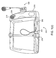
- FIG. 10 shows a perspective view of an electrographic position location apparatus without a data cartridge.
- a microphone structure 902 with a head portion and a neck is shown.
- the microphone structure 902 is a dummy microphone structure with any of the features described above.
- An opening 904 for a microphone may be present near the base of the microphone structure 902 .
- the microphone structure 902 is directly coupled to the platform 900 , the advantages described above with respect to the dummy microphone are still applicable for this embodiment.
- the user's mouth will be spaced at a consistent distance from the actual recording microphone, whether it is in the head portion of the microphone structure 902 or is under the opening 904 in the platform 900 , thereby providing higher quality recordings.
- Any of the above-described features for the data cartridges and/or the above-described electrographic position location apparatuses can be combined any suitable manner with the features shown in FIG. 10 .
- the recording electronics that are shown in FIGS. 4 - 5 A- 5 J are described with reference to a data cartridge, they can be used with in an electrographic position location apparatus that does not need to use a data cartridge.
Abstract
Description
Claims (11)
Priority Applications (1)
| Application Number | Priority Date | Filing Date | Title |
|---|---|---|---|
| US10/750,982 US7792480B2 (en) | 2003-01-03 | 2004-01-02 | Electrographic position location apparatus including recording capability and data cartridge including microphone |
Applications Claiming Priority (4)
| Application Number | Priority Date | Filing Date | Title |
|---|---|---|---|
| US43777003P | 2003-01-03 | 2003-01-03 | |
| US48744003P | 2003-07-14 | 2003-07-14 | |
| US51227503P | 2003-10-17 | 2003-10-17 | |
| US10/750,982 US7792480B2 (en) | 2003-01-03 | 2004-01-02 | Electrographic position location apparatus including recording capability and data cartridge including microphone |
Publications (2)
| Publication Number | Publication Date |
|---|---|
| US20040197757A1 US20040197757A1 (en) | 2004-10-07 |
| US7792480B2 true US7792480B2 (en) | 2010-09-07 |
Family
ID=32719181
Family Applications (1)
| Application Number | Title | Priority Date | Filing Date |
|---|---|---|---|
| US10/750,982 Expired - Fee Related US7792480B2 (en) | 2003-01-03 | 2004-01-02 | Electrographic position location apparatus including recording capability and data cartridge including microphone |
Country Status (3)
| Country | Link |
|---|---|
| US (1) | US7792480B2 (en) |
| AU (1) | AU2003300141A1 (en) |
| WO (1) | WO2004064009A1 (en) |
Families Citing this family (24)
| Publication number | Priority date | Publication date | Assignee | Title |
|---|---|---|---|---|
| CN101421766A (en) * | 2004-02-12 | 2009-04-29 | 美泰有限公司 | E-book based on the Internet |
| US20050266386A1 (en) * | 2004-05-28 | 2005-12-01 | Leapfrog Enterprises, Inc. | Print media apparatus including stroke recognition |
| US20070042335A1 (en) * | 2005-05-11 | 2007-02-22 | Ctb Mcgraw-Hill | System and method for assessment or survey response collection using a remote, digitally recording user input device |
| US8469766B2 (en) * | 2005-10-21 | 2013-06-25 | Patent Category Corp. | Interactive toy system |
| US20080303787A1 (en) * | 2005-10-21 | 2008-12-11 | Zheng Yu Brian | Touch Screen Apparatus And Methods |
| US20080139080A1 (en) * | 2005-10-21 | 2008-06-12 | Zheng Yu Brian | Interactive Toy System and Methods |
| US8157611B2 (en) * | 2005-10-21 | 2012-04-17 | Patent Category Corp. | Interactive toy system |
| US7808385B2 (en) * | 2005-10-21 | 2010-10-05 | Patent Category Corp. | Interactive clothing system |
| US20070093170A1 (en) * | 2005-10-21 | 2007-04-26 | Yu Zheng | Interactive toy system |
| US20080153594A1 (en) * | 2005-10-21 | 2008-06-26 | Zheng Yu Brian | Interactive Toy System and Methods |
| US20080305873A1 (en) * | 2005-10-21 | 2008-12-11 | Zheng Yu Brian | Universal Toy Controller System And Methods |
| US20080300061A1 (en) * | 2005-10-21 | 2008-12-04 | Zheng Yu Brian | Online Interactive Game System And Methods |
| US20080032275A1 (en) * | 2006-07-21 | 2008-02-07 | Yu Zheng | Interactive system |
| US20080032276A1 (en) * | 2006-07-21 | 2008-02-07 | Yu Zheng | Interactive system |
| US20080098315A1 (en) * | 2006-10-18 | 2008-04-24 | Dao-Liang Chou | Executing an operation associated with a region proximate a graphic element on a surface |
| US7909697B2 (en) * | 2007-04-17 | 2011-03-22 | Patent Catefory Corp. | Hand-held interactive game |
| US20080288870A1 (en) * | 2007-05-14 | 2008-11-20 | Yu Brian Zheng | System, methods, and apparatus for multi-user video communications |
| US20080288989A1 (en) * | 2007-05-14 | 2008-11-20 | Zheng Yu Brian | System, Methods and Apparatus for Video Communications |
| US8926395B2 (en) * | 2007-11-28 | 2015-01-06 | Patent Category Corp. | System, method, and apparatus for interactive play |
| US20110233272A1 (en) * | 2008-09-16 | 2011-09-29 | Yau Yim Wai | Electronic book with clamping device for superposition of multi-books |
| CN102107567B (en) * | 2009-09-30 | 2015-11-25 | 深圳市王菱科技开发有限公司 | Be provided with the data volume of windows system on paper |
| US20130002543A1 (en) * | 2010-03-23 | 2013-01-03 | Yau Yim Wai | Interactive presentation system of electronic reading device with on-paper window system |
| US8961183B2 (en) * | 2012-06-04 | 2015-02-24 | Hallmark Cards, Incorporated | Fill-in-the-blank audio-story engine |
| US9934817B2 (en) * | 2013-10-04 | 2018-04-03 | Hallmark Cards, Incorporated | System for recording, sharing, and storing audio |
Citations (33)
| Publication number | Priority date | Publication date | Assignee | Title |
|---|---|---|---|---|
| US3702515A (en) * | 1972-01-03 | 1972-11-14 | Mattel Inc | Telephone-talking doll simulator |
| US3793766A (en) * | 1972-08-21 | 1974-02-26 | Mattel Inc | Telephone-talking figure toy simulator |
| WO1987006752A1 (en) | 1986-05-01 | 1987-11-05 | Trevor Gwilym Lloyd | Language teaching apparatus |
| US4884974A (en) | 1987-12-21 | 1989-12-05 | View-Master Ideal Group, Inc. | Interactive talking book and audio player assembly |
| US5167508A (en) | 1989-08-21 | 1992-12-01 | Mc Taggart Stephen I | Electronic book |
| US5419705A (en) | 1993-08-11 | 1995-05-30 | Sandviks Bokforlag | Talking book with removable sound source |
| US5437552A (en) | 1993-08-13 | 1995-08-01 | Western Publishing Co., Inc. | Interactive audio-visual work |
| US5453013A (en) | 1989-10-12 | 1995-09-26 | Western Publishing Co., Inc. | Interactive audio visual work |
| US5466158A (en) * | 1994-02-14 | 1995-11-14 | Smith, Iii; Jay | Interactive book device |
| US5485176A (en) | 1991-11-21 | 1996-01-16 | Kabushiki Kaisha Sega Enterprises | Information display system for electronically reading a book |
| US5511980A (en) | 1994-02-23 | 1996-04-30 | Leapfrog Rbt, L.L.C. | Talking phonics interactive learning device |
| US5574519A (en) | 1994-05-03 | 1996-11-12 | Eastman Kodak Company | Talking photoalbum |
| US5575659A (en) | 1991-02-22 | 1996-11-19 | Scanna Technology Limited | Document interpreting systems |
| US5603652A (en) * | 1995-06-22 | 1997-02-18 | Rothschild; Omri | Doll assembly |
| US5636995A (en) | 1995-01-17 | 1997-06-10 | Stephen A. Schwartz | Interactive story book and graphics tablet apparatus and methods for operating the same |
| US5679049A (en) * | 1995-02-02 | 1997-10-21 | Robert W. Jeffway, Jr. | Toy telephone recording and playback |
| US5707240A (en) | 1996-03-28 | 1998-01-13 | Eastman Kodak Company | Album with means for magnetically determining page position |
| US5888070A (en) | 1996-08-01 | 1999-03-30 | La Tour; Kathryn E. | Electronic aid for reading practice |
| US6028556A (en) * | 1998-07-08 | 2000-02-22 | Shicoh Engineering Company, Ltd. | Portable radio communication apparatus |
| US6148173A (en) | 1998-02-26 | 2000-11-14 | Eastman Kodak Company | System for initialization of an image holder that stores images with associated audio segments |
| US6167233A (en) | 1998-08-31 | 2000-12-26 | Voicemark, Llc | Device for recording multiple discrete messages for a book |
| USD436100S1 (en) * | 1999-07-08 | 2001-01-09 | Publications International, Ltd. | Electronic sound book with microphone |
| US6246570B1 (en) * | 1998-06-10 | 2001-06-12 | Samsung Electronics Co., Ltd. | Portable computer having a microphone |
| US6305732B1 (en) * | 1999-05-18 | 2001-10-23 | Mannesmann Vdo Ag | Dashboard with integrated directional microphone |
| US20020054029A1 (en) * | 2000-11-28 | 2002-05-09 | Glancy John Thomas | Interactive display system |
| US6421524B1 (en) * | 2000-05-30 | 2002-07-16 | International Business Machines Corporation | Personalized electronic talking book |
| US6516181B1 (en) * | 2001-07-25 | 2003-02-04 | Debbie Giampapa Kirwan | Interactive picture book with voice recording features and method of use |
| US6608618B2 (en) | 2001-06-20 | 2003-08-19 | Leapfrog Enterprises, Inc. | Interactive apparatus using print media |
| US20030162162A1 (en) | 2002-02-06 | 2003-08-28 | Leapfrog Enterprises, Inc. | Write on interactive apparatus and method |
| US6641401B2 (en) | 2001-06-20 | 2003-11-04 | Leapfrog Enterprises, Inc. | Interactive apparatus with templates |
| US6661405B1 (en) * | 2000-04-27 | 2003-12-09 | Leapfrog Enterprises, Inc. | Electrographic position location apparatus and method |
| US6668156B2 (en) * | 2000-04-27 | 2003-12-23 | Leapfrog Enterprises, Inc. | Print media receiving unit including platform and print media |
| US7035091B2 (en) * | 2002-02-28 | 2006-04-25 | Accenture Global Services Gmbh | Wearable computer system and modes of operating the system |
-
2003
- 2003-12-31 WO PCT/US2003/041707 patent/WO2004064009A1/en not_active Application Discontinuation
- 2003-12-31 AU AU2003300141A patent/AU2003300141A1/en not_active Abandoned
-
2004
- 2004-01-02 US US10/750,982 patent/US7792480B2/en not_active Expired - Fee Related
Patent Citations (34)
| Publication number | Priority date | Publication date | Assignee | Title |
|---|---|---|---|---|
| US3702515A (en) * | 1972-01-03 | 1972-11-14 | Mattel Inc | Telephone-talking doll simulator |
| US3793766A (en) * | 1972-08-21 | 1974-02-26 | Mattel Inc | Telephone-talking figure toy simulator |
| WO1987006752A1 (en) | 1986-05-01 | 1987-11-05 | Trevor Gwilym Lloyd | Language teaching apparatus |
| US4884974A (en) | 1987-12-21 | 1989-12-05 | View-Master Ideal Group, Inc. | Interactive talking book and audio player assembly |
| US5167508A (en) | 1989-08-21 | 1992-12-01 | Mc Taggart Stephen I | Electronic book |
| US5453013A (en) | 1989-10-12 | 1995-09-26 | Western Publishing Co., Inc. | Interactive audio visual work |
| US5575659A (en) | 1991-02-22 | 1996-11-19 | Scanna Technology Limited | Document interpreting systems |
| US5485176A (en) | 1991-11-21 | 1996-01-16 | Kabushiki Kaisha Sega Enterprises | Information display system for electronically reading a book |
| US5419705A (en) | 1993-08-11 | 1995-05-30 | Sandviks Bokforlag | Talking book with removable sound source |
| US5531600A (en) | 1993-08-13 | 1996-07-02 | Western Publishing Co., Inc. | Interactive audio-visual work |
| US5437552A (en) | 1993-08-13 | 1995-08-01 | Western Publishing Co., Inc. | Interactive audio-visual work |
| US5466158A (en) * | 1994-02-14 | 1995-11-14 | Smith, Iii; Jay | Interactive book device |
| US5511980A (en) | 1994-02-23 | 1996-04-30 | Leapfrog Rbt, L.L.C. | Talking phonics interactive learning device |
| US5574519A (en) | 1994-05-03 | 1996-11-12 | Eastman Kodak Company | Talking photoalbum |
| US5636995A (en) | 1995-01-17 | 1997-06-10 | Stephen A. Schwartz | Interactive story book and graphics tablet apparatus and methods for operating the same |
| US5679049A (en) * | 1995-02-02 | 1997-10-21 | Robert W. Jeffway, Jr. | Toy telephone recording and playback |
| US5603652A (en) * | 1995-06-22 | 1997-02-18 | Rothschild; Omri | Doll assembly |
| US5707240A (en) | 1996-03-28 | 1998-01-13 | Eastman Kodak Company | Album with means for magnetically determining page position |
| US5888070A (en) | 1996-08-01 | 1999-03-30 | La Tour; Kathryn E. | Electronic aid for reading practice |
| US6148173A (en) | 1998-02-26 | 2000-11-14 | Eastman Kodak Company | System for initialization of an image holder that stores images with associated audio segments |
| US6246570B1 (en) * | 1998-06-10 | 2001-06-12 | Samsung Electronics Co., Ltd. | Portable computer having a microphone |
| US6028556A (en) * | 1998-07-08 | 2000-02-22 | Shicoh Engineering Company, Ltd. | Portable radio communication apparatus |
| US6167233A (en) | 1998-08-31 | 2000-12-26 | Voicemark, Llc | Device for recording multiple discrete messages for a book |
| US6305732B1 (en) * | 1999-05-18 | 2001-10-23 | Mannesmann Vdo Ag | Dashboard with integrated directional microphone |
| USD436100S1 (en) * | 1999-07-08 | 2001-01-09 | Publications International, Ltd. | Electronic sound book with microphone |
| US6661405B1 (en) * | 2000-04-27 | 2003-12-09 | Leapfrog Enterprises, Inc. | Electrographic position location apparatus and method |
| US6668156B2 (en) * | 2000-04-27 | 2003-12-23 | Leapfrog Enterprises, Inc. | Print media receiving unit including platform and print media |
| US6421524B1 (en) * | 2000-05-30 | 2002-07-16 | International Business Machines Corporation | Personalized electronic talking book |
| US20020054029A1 (en) * | 2000-11-28 | 2002-05-09 | Glancy John Thomas | Interactive display system |
| US6608618B2 (en) | 2001-06-20 | 2003-08-19 | Leapfrog Enterprises, Inc. | Interactive apparatus using print media |
| US6641401B2 (en) | 2001-06-20 | 2003-11-04 | Leapfrog Enterprises, Inc. | Interactive apparatus with templates |
| US6516181B1 (en) * | 2001-07-25 | 2003-02-04 | Debbie Giampapa Kirwan | Interactive picture book with voice recording features and method of use |
| US20030162162A1 (en) | 2002-02-06 | 2003-08-28 | Leapfrog Enterprises, Inc. | Write on interactive apparatus and method |
| US7035091B2 (en) * | 2002-02-28 | 2006-04-25 | Accenture Global Services Gmbh | Wearable computer system and modes of operating the system |
Non-Patent Citations (2)
| Title |
|---|
| "Fundamentals of Reading: A Parent's Guide to using the Record 'n Learn(TM) Pad learning toy;" 9 pages; VTECH. |
| "Fundamentals of Reading: A Parent's Guide to using the Record 'n Learn™ Pad learning toy;" 9 pages; VTECH. |
Also Published As
| Publication number | Publication date |
|---|---|
| WO2004064009A9 (en) | 2004-09-16 |
| WO2004064009A1 (en) | 2004-07-29 |
| AU2003300141A1 (en) | 2004-08-10 |
| US20040197757A1 (en) | 2004-10-07 |
Similar Documents
| Publication | Publication Date | Title |
|---|---|---|
| US7792480B2 (en) | Electrographic position location apparatus including recording capability and data cartridge including microphone | |
| US7106309B2 (en) | Interactive apparatus using print media | |
| US8952887B1 (en) | Interactive references to related application | |
| US8787672B2 (en) | Reader device having various functionalities | |
| US7347760B2 (en) | Interactive toy | |
| US6641401B2 (en) | Interactive apparatus with templates | |
| US6421524B1 (en) | Personalized electronic talking book | |
| US5829985A (en) | Interactive children's game | |
| US20040104890A1 (en) | Compact book and apparatus using print media | |
| JP2008139826A (en) | Interactive learning tool | |
| US9111463B2 (en) | Interactive speech synthesizer for enabling people who cannot talk but who are familiar with use of anonym moveable picture communication to autonomously communicate using verbal language | |
| KR100737427B1 (en) | Many languages studying system and operation process of including teaching material by paper | |
| US7167675B2 (en) | Magnetic switch and apparatus including magnetic switch | |
| KR20040016891A (en) | Interactive apparatus using print media | |
| US20220375359A1 (en) | Interactive media | |
| KR102082181B1 (en) | Electronic Pen based on Artificial Intelligence, System for Playing Contents using Electronic Pen based on artificial intelligence and Method thereof | |
| KR20100024700A (en) | A musical board and a playing system having thereof | |
| US20060020470A1 (en) | Interactive speech synthesizer for enabling people who cannot talk but who are familiar with use of picture exchange communication to autonomously communicate using verbal language | |
| US20070166004A1 (en) | Robot system using menu selection card having printed menu codes and pictorial symbols | |
| CN215265153U (en) | Pinyin learning equipment | |
| WO2010029539A1 (en) | Customized educational toy | |
| CN211742320U (en) | English natural phonetic learning game multifunctional board | |
| KR200379520Y1 (en) | A toy using blocks | |
| KR20220040280A (en) | Apparatus for expressing intention | |
| JP3013779U (en) | Educational equipment |
Legal Events
| Date | Code | Title | Description |
|---|---|---|---|
| AS | Assignment |
Owner name: LEAPFROG ENTERPRISES, INC., CALIFORNIA Free format text: ASSIGNMENT OF ASSIGNORS INTEREST;ASSIGNORS:MUSOLF, TOM;FREEMAN, RICHARD GLEN;MUCH, MICHAEL P.;REEL/FRAME:014703/0762;SIGNING DATES FROM 20030407 TO 20040324 Owner name: LEAPFROG ENTERPRISES, INC., CALIFORNIA Free format text: ASSIGNMENT OF ASSIGNORS INTEREST;ASSIGNORS:MUSOLF, TOM;FREEMAN, RICHARD GLEN;MUCH, MICHAEL P.;SIGNING DATES FROM 20030407 TO 20040324;REEL/FRAME:014703/0762 |
|
| AS | Assignment |
Owner name: BANK OF AMERICA, N.A., CALIFORNIA Free format text: SECURITY AGREEMENT;ASSIGNORS:LEAPFROG ENTERPRISES, INC.;LFC VENTURES, LLC;REEL/FRAME:021511/0441 Effective date: 20080828 Owner name: BANK OF AMERICA, N.A.,CALIFORNIA Free format text: SECURITY AGREEMENT;ASSIGNORS:LEAPFROG ENTERPRISES, INC.;LFC VENTURES, LLC;REEL/FRAME:021511/0441 Effective date: 20080828 |
|
| AS | Assignment |
Owner name: BANK OF AMERICA, N.A., CALIFORNIA Free format text: AMENDED AND RESTATED INTELLECTUAL PROPERTY SECURITY AGREEMENT;ASSIGNOR:LEAPFROG ENTERPRISES, INC.;REEL/FRAME:023379/0220 Effective date: 20090813 Owner name: BANK OF AMERICA, N.A.,CALIFORNIA Free format text: AMENDED AND RESTATED INTELLECTUAL PROPERTY SECURITY AGREEMENT;ASSIGNOR:LEAPFROG ENTERPRISES, INC.;REEL/FRAME:023379/0220 Effective date: 20090813 |
|
| STCF | Information on status: patent grant |
Free format text: PATENTED CASE |
|
| AS | Assignment |
Owner name: BANK OF AMERICA, N.A., CALIFORNIA Free format text: INTELLECTUAL PROPERTY SECURITY AGREEMENT SUPPLEMENT;ASSIGNOR:LEAPFROG ENTERPRISES, INC.;REEL/FRAME:025879/0935 Effective date: 20110131 |
|
| FPAY | Fee payment |
Year of fee payment: 4 |
|
| MAFP | Maintenance fee payment |
Free format text: PAYMENT OF MAINTENANCE FEE, 8TH YEAR, LARGE ENTITY (ORIGINAL EVENT CODE: M1552) Year of fee payment: 8 |
|
| FEPP | Fee payment procedure |
Free format text: MAINTENANCE FEE REMINDER MAILED (ORIGINAL EVENT CODE: REM.); ENTITY STATUS OF PATENT OWNER: LARGE ENTITY |
|
| LAPS | Lapse for failure to pay maintenance fees |
Free format text: PATENT EXPIRED FOR FAILURE TO PAY MAINTENANCE FEES (ORIGINAL EVENT CODE: EXP.); ENTITY STATUS OF PATENT OWNER: LARGE ENTITY |
|
| STCH | Information on status: patent discontinuation |
Free format text: PATENT EXPIRED DUE TO NONPAYMENT OF MAINTENANCE FEES UNDER 37 CFR 1.362 |
|
| FP | Lapsed due to failure to pay maintenance fee |
Effective date: 20220907 |