US7792451B2 - Image fixing apparatus, image forming apparatus using the same, and image fixing temperature control method thereof - Google Patents
Image fixing apparatus, image forming apparatus using the same, and image fixing temperature control method thereof Download PDFInfo
- Publication number
- US7792451B2 US7792451B2 US11/877,788 US87778807A US7792451B2 US 7792451 B2 US7792451 B2 US 7792451B2 US 87778807 A US87778807 A US 87778807A US 7792451 B2 US7792451 B2 US 7792451B2
- Authority
- US
- United States
- Prior art keywords
- heater
- sensor
- image
- temperature
- fixing
- Prior art date
- Legal status (The legal status is an assumption and is not a legal conclusion. Google has not performed a legal analysis and makes no representation as to the accuracy of the status listed.)
- Active, expires
Links
Images


Classifications
-
- G—PHYSICS
- G03—PHOTOGRAPHY; CINEMATOGRAPHY; ANALOGOUS TECHNIQUES USING WAVES OTHER THAN OPTICAL WAVES; ELECTROGRAPHY; HOLOGRAPHY
- G03G—ELECTROGRAPHY; ELECTROPHOTOGRAPHY; MAGNETOGRAPHY
- G03G15/00—Apparatus for electrographic processes using a charge pattern
- G03G15/20—Apparatus for electrographic processes using a charge pattern for fixing, e.g. by using heat
- G03G15/2003—Apparatus for electrographic processes using a charge pattern for fixing, e.g. by using heat using heat
- G03G15/2014—Apparatus for electrographic processes using a charge pattern for fixing, e.g. by using heat using heat using contact heat
- G03G15/2039—Apparatus for electrographic processes using a charge pattern for fixing, e.g. by using heat using heat using contact heat with means for controlling the fixing temperature
-
- G—PHYSICS
- G03—PHOTOGRAPHY; CINEMATOGRAPHY; ANALOGOUS TECHNIQUES USING WAVES OTHER THAN OPTICAL WAVES; ELECTROGRAPHY; HOLOGRAPHY
- G03G—ELECTROGRAPHY; ELECTROPHOTOGRAPHY; MAGNETOGRAPHY
- G03G15/00—Apparatus for electrographic processes using a charge pattern
- G03G15/20—Apparatus for electrographic processes using a charge pattern for fixing, e.g. by using heat
- G03G15/2003—Apparatus for electrographic processes using a charge pattern for fixing, e.g. by using heat using heat
- G03G15/2014—Apparatus for electrographic processes using a charge pattern for fixing, e.g. by using heat using heat using contact heat
- G03G15/2053—Structural details of heat elements, e.g. structure of roller or belt, eddy current, induction heating
-
- G—PHYSICS
- G03—PHOTOGRAPHY; CINEMATOGRAPHY; ANALOGOUS TECHNIQUES USING WAVES OTHER THAN OPTICAL WAVES; ELECTROGRAPHY; HOLOGRAPHY
- G03G—ELECTROGRAPHY; ELECTROPHOTOGRAPHY; MAGNETOGRAPHY
- G03G15/00—Apparatus for electrographic processes using a charge pattern
- G03G15/20—Apparatus for electrographic processes using a charge pattern for fixing, e.g. by using heat
- G03G15/2003—Apparatus for electrographic processes using a charge pattern for fixing, e.g. by using heat using heat
- G03G15/2014—Apparatus for electrographic processes using a charge pattern for fixing, e.g. by using heat using heat using contact heat
- G03G15/2064—Apparatus for electrographic processes using a charge pattern for fixing, e.g. by using heat using heat using contact heat combined with pressure
-
- G—PHYSICS
- G03—PHOTOGRAPHY; CINEMATOGRAPHY; ANALOGOUS TECHNIQUES USING WAVES OTHER THAN OPTICAL WAVES; ELECTROGRAPHY; HOLOGRAPHY
- G03G—ELECTROGRAPHY; ELECTROPHOTOGRAPHY; MAGNETOGRAPHY
- G03G2215/00—Apparatus for electrophotographic processes
- G03G2215/20—Details of the fixing device or porcess
- G03G2215/2003—Structural features of the fixing device
- G03G2215/2016—Heating belt
- G03G2215/2025—Heating belt the fixing nip having a rotating belt support member opposing a pressure member
Definitions
- aspects of the present invention relate to an image forming apparatus, and more particularly, to an image fixing apparatus to fix an image onto a printing medium, an image forming apparatus having the same, and an image fixing temperature control method thereof.
- An image forming apparatus such as, for example, a multi-function image forming apparatus that combines various functions such as a copier, a printer, or a facsimile, mainly operates to recreate an input image signal onto a printing medium.
- An image forming apparatus generally includes a paper feeder to feed a printing medium, a developer to develop an electrostatic latent image on a photoconductive medium, a transfer mechanism to transfer the developed image onto the printing medium, and an image fixing apparatus to fix the transferred image in the printing medium.
- An example of a conventional image fixing apparatus is illustrated in FIG. 1 .
- a conventional image fixing apparatus 1 of an image forming apparatus includes a heating roller 10 , which houses a heater 11 therein, and a pressing roller 20 , which is pressed towards the heating roller 10 .
- a temperature sensor 30 is installed on the outer circumference of the heating roller 10 to measure the temperature of the heating roller 10 .
- a thermal sensor (such as a thermistor or thermostat) is generally used as the temperature sensor 30 .
- the temperature sensor 30 detects the surface temperature of the heating roller 10 , generally from a spot near the middle part of the heating roller 10 . Therefore, the temperature of the heater 11 is controlled according to the result of the sensing by the temperature sensor 30 .
- the temperature sensor 30 is installed on the outer surface of the heating roller 10 while the heater 11 is inside the heating roller 10 , it is difficult to detect accurately the temperature of the heater 11 . Accordingly, it is difficult to control the temperature of the heater 11 accurately, and bad image fixation may occur due to overheating or underheating of the heater 11 .
- FIG. 2 shows a temperature variation along an axis of the roller 10 both at an early stage in an operation of the image fixing apparatus (below T 0 ) and at a later stage of the operation of the image fixing apparatus (above T 0 ).
- S.P. represents a position at or near a midpoint of the axis where the temperature sensor 30 detects the temperature of the heater 11 .
- T 1 represents the early stage temperature variation in the absence of control and T 2 represents the early stage temperature variation, where the temperature is controlled to bring the temperature at S.P. up to the reference temperature T 0 .
- T 3 represents the later stage temperature variation in the absence of control and T 4 represents the later stage temperature variation, where the temperature is controlled to bring the temperature at S.P.
- the temperature sensor 30 detects the temperature at only one spot (S.P) at or near the middle part of the heating roller 10 , as illustrated in FIG. 2 , and since the middle (S.P.) of the roller 10 tends to heat up more quickly than the ends of the roller, a large temperature gap ( ⁇ T 1 ) is generated at the ends of the roller 10 between the previously fixed reference temperature (T 0 ) and the controlled temperature (T 2 ) at the early stage operation, even when the middle of the roller has reached the reference temperature T 0 . Similarly, since the middle S.P.
- ⁇ T 2 a large temperature gap ( ⁇ T 2 ) is generated at the ends of the roller 10 between the previously fixed reference temperature (T 0 ) and the controlled temperature (T 4 ) after a long period of operation.
- a large temperature gap ( ⁇ T 1 ) occurs between the lowest value of the controlled early stage temperature of the early stage temperature (T 2 ) and the predetermined image fixing reference temperature (T 0 ).
- a large temperature gap ( ⁇ T 2 ) also occurs between the highest value of the controlled long time operation temperature (T 4 ) and the predetermined image fixing reference temperature (T 0 ).
- the temperature gaps ( ⁇ T 1 , ⁇ T 2 ) cause problems such as over-fixing, under-fixing, or shortened lifespan.
- the first image fixing on the printing medium P by the image fixing apparatus 1 be shortened by reducing the heating volume so that the heater 11 can reach a desired high temperature to heat the heating roller 10 within a short time. In this case, however, if the temperature is sensed inaccurately by the temperature sensor 30 , the heater 11 may be damaged.
- aspects of the present invention provide an image fixing apparatus which senses temperature of a heater accurately, and thus is able to control the heater with accuracy, an image forming apparatus having the image fixing apparatus, and a fixing temperature control method thereof.
- an image fixing apparatus of an image forming apparatus includes a pair of fixing rollers, a heater housed inside at least one of the pair of fixing rollers, and a sensor integrally formed with the heater, to detect temperatures of the heater from a plurality of sensing positions.
- the senor includes an array of sensing units connected in parallel to the plurality of sensing positions, and generates one sensing signal.
- an insulating member may be disposed between the heater and the sensor.
- the heater may include a multi-layer heating body, and the sensor may be disposed between the layers of the heating body.
- the sensor may detect temperatures of the heating body from at least two sensing positions.
- the heater and the sensor may be mixed with each other by ceramic processing.
- the array of sensors generate average temperature information of a plurality of sensing positions.
- a switch may further be provided, to control the on/off status of the heater, based on a comparison between the average temperature information generated from the sensor and a reference temperature.
- the switch controls the on/off status of the heater so that the average temperature corresponds to the reference temperature.
- an image forming apparatus includes an image forming section to form an image on a printing medium, and an image fixing apparatus to fix the image into the printing medium, wherein the image fixing apparatus includes a pair of fixing rollers, a heater housed inside at least one of the pair of fixing rollers, a sensor including a plurality of sensing units connected in parallel to detect temperatures of the heater from a plurality of sensing positions, and a switch to control the on/off status of the heater based on information detected at the sensor.
- a method of controlling an image fixing temperature of an image forming apparatus may include generating average temperature information from a plurality of sensing positions of a heater, and controlling driving of the heater based on the temperature information.
- the generating may include sensing, by an array of sensing units connected in parallel, temperatures of the heaters from a plurality of sensing positions, and computing an average temperature based on temperature information sensed from the plurality of sensing positions.
- the controlling may include comparing the average temperature with a reference fixing temperature, and switching off the heater if the average temperature exceeds the reference temperature, and switching on the heater, if the average temperature is lower than the reference temperature.
- FIG. 1 is a schematic cross sectional view illustrating a conventional image fixing apparatus of an image forming apparatus
- FIG. 2 is a graph that illustrates temperatures of the image fixing apparatus of FIG. 1 across a width of the heating roller;
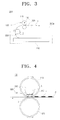
- FIG. 3 is a schematic cross-sectional view an image forming apparatus according to an exemplary embodiment of the present invention.
- FIG. 4 is a schematic cross sectional view of the image fixing apparatus of FIG. 3 ;
- FIG. 5 is an enlarged view of an area in circle A of FIG. 4 ;
- FIGS. 6A and 6B are schematic representations a heating body and a sensor of the image fixing apparatus of FIG. 4 ;
- FIG. 7 is a graph that illustrates temperatures of the image fixing apparatus of FIG. 4 across a width of the heating roller.
- FIG. 8 is a flowchart illustrating an image fixing temperature control method of an image forming apparatus according to an exemplary embodiment of the present invention.
- an image forming apparatus 200 includes an image forming section 220 and an image fixing apparatus 100 .
- a paper cassette 210 is removably attached to a main body 210 a of the image forming apparatus 200 .
- the image forming section 220 develops an image on a printing medium P.
- the paper cassette 210 and the image forming section 220 have substantially the same technical construction as is known in the art, and therefore, a detailed explanation thereof will be omitted for the sake of brevity.
- the cassette 210 can be replaced by a tray or manual feed slot in other aspects.
- the image fixing apparatus 100 will be explained in detail below, with reference to the accompanying drawings.
- the image fixing apparatus 100 includes a heating roller 110 , a pressing roller 120 , a heater 130 , a sensor 140 and a switch 170 .
- the heating roller 110 and the pressing roller 120 rotate in contact with each other.
- One of the heating roller 110 and the pressing roller 120 receives force from a driving source (not shown) to be driven.
- the other roller which does not receive force from the driving source (not shown), is passively rotated by contact with the counterpart roller receiving the driving force.
- both ends of the heating roller 110 and the pressing roller 120 are supported by bearings (not shown).
- bearings not shown.
- both the heating roller 110 and the pressing rollers 120 may receive driving force from the driving source (not shown) to be rotated.
- the heating and pressing rollers 110 , 120 are formed from materials such as stainless steel and are coated on their outer circumferences with materials such as Teflon, to prevent the toner image T formed on a printing medium P from passing onto the heating and pressing rollers 110 , 120 , when the printing medium P passes between the heating and pressing rollers 110 , 120 .
- the pressing roller 120 is squeezed towards the heating roller 110 in a rotating motion, thereby creating a nip area N between the heating and pressing rollers 110 , 120 . Accordingly, both ends of the pressing rollers 120 are supported by an elastic member such as a spring (not shown).
- the heater 130 is housed inside the heating roller 110 , to heat the heating roller 110 at a predetermined fixing temperature.
- the heater 130 includes a heating body 131 and a support member 132 to support the heating body 131 .
- the heating body 131 may be a resistor, which generates heat from externally-supplied electricity. However, it is to be understood that other types of heat-generating elements may be used.
- the heating body 131 is extended in a direction along an axis of rotation of the heating roller 110 , and transmits heat to the inner circumference of the heating roller 110 by radiation.
- the heating body 131 has a multi-layer structure, that is, the heating body 131 has a plurality of layers.
- the support member 132 supports the heating body 131 so that the heating body 131 is spaced apart from the inner side of the heating roller 110 and faces the pressing roller 120 .
- the support member 132 supports the heating body 131 so that the heating body 131 is maintained close to the nip area N formed between the heating roller 110 and the pressing roller 120 .
- heat generated at the heating body 131 is transmitted to the nip area N within a short time.
- the sensor 140 is integrally formed with the heater 130 , to sense temperatures of the heater 130 at a plurality of sensing positions. Referring to FIG. 5 , the sensor 140 is disposed between the layers of the heating body 131 . An insulating member 150 is disposed between the sensor 140 and the heater 130 for electric insulation.
- the sensor 140 includes sensing units 141 to detect the temperatures of the heating body 131 at least three sensing positions.
- the sensing units 141 are spaced a predetermined distance away from each other along the axis of the heating roller 110 , to correspond to the heating body 131 , which extends along the axis of the heating roller 110 .
- fewer or more sensing units 141 can be used and that the relative placement of the sensing units 141 to each other can be varied and need not be equal distances as shown.
- a conductive member 142 such as, for example, a wire, connects the sensing units 141 in parallel, to enable the exchange of electric signals.
- an array type sensor in which a plurality of sensing units 141 are connected by one conductive member 142 in a parallel relation, may be implemented. As the sensing units 141 detect the temperatures, an average temperatures is also computed and output.
- the sensing units 141 may be thermal sensors, such as thermistors, which change resistance value or generate electricity in response to heat.
- the sensing units 141 are connected in parallel to first to third sensing positions (S. P 1 , S. P 2 , S. P 3 ) at equal intervals.
- first to third sensing positions S. P 1 , S. P 2 , S. P 3
- the sensing units 141 may be connected in parallel to first and second sensing positions (S. P 1 , S. P 2 ) of the heating body 131 .
- the sensor 140 including the sensing units 141 , and the heater 130 may be mixed integrally with each other by ceramic processing to form the ceramic support member 132 to hold the heating body 131 and the sensor 140 .
- the support member 132 that supports the heating body 131 and the sensor 140 may be made from a ceramic material having highly insulating and non-thermal characteristics and low heat resistance.
- the switch 170 controls the on/off status of the heating body 131 , based on the average temperature sensed from the sensor 140 . As the average temperature of the heating body 131 is computed by the sensor 140 , the switch 170 compares the average temperature with a reference temperature T 0 . Accordingly, the switch 170 may exchange signals with a memory 180 that stores the reference temperature T 0 .
- the switch 170 turns off the heating body 131 , so that the temperature of the heating body 131 decreases. If the average temperature is lower than the reference temperature T 0 , the switch 170 keeps the heating body 131 in an “on” status, so that the temperature of the heating body 131 increases.
- the switch 170 controls on/off status of the heating body 131 so that the average temperature corresponds to the reference temperature T 0 .
- the switch 170 may be implemented using a processor and/or computer to control at least the on/off status of the sensor 140 .
- An analog-to-digital converter 160 may be provided between the sensor 140 and the switch 170 , to digitize the signal from the sensor 140 so that the switch 170 can read the average temperature generated from the sensor 140 .
- the analog-to-digital converter 160 is connected with the array of sensing units 141 , which are connected in parallel via a conductive member 142 . Compared to serial sensors, which would require separate conductive members to connect an analog-to-digital converter 160 with individual serial sensing units, the above structure according to an embodiment of the present invention is simpler.
- the switch 170 compares the sensed temperature with the reference temperature T 0 stored in a memory 180 and accordingly controls the on/off state of the sensor 140 .
- the image forming section 220 forms an image on a printing medium P fed from the paper cassette 210 .
- the printing medium P bearing the image is then conveyed between the heating roller 110 and the pressing roller 120 of the image fixing apparatus 100 .
- the heating roller 110 is heated by the fixing heat generated from the heating body 131 , and the pressing roller 120 is squeezed against the heating roller 110 by the support of the elastic member (not shown). Accordingly, the nip area N is created on the heating roller 110 and the pressing roller 120 which are squeezed against each other.
- the printing medium P bears a developed image thereon, and the developed image is fixed in the printing medium P as the printing medium P passes the nip area N. The printing medium P is then discharged outside the main body 200 a of the image forming apparatus.
- the heating of the heating roller 110 will be explained in more detail below.
- the heating body 131 housed inside the heating roller 110 and facing the nip area N is heated. Heat is generated from the heating body 131 , and radiated to the heating roller 110 , which is rotated in tight contact with the pressing roller 120 , thereby heating the heating roller 110 . Because the heating body 131 is supported by the support member 132 to be close to the nip area N, the nip area N can be heated to a desired temperature faster than other areas.
- sensor 140 including the sensing units 141 is integrally formed between the layers of the heating body 131 , to sense the heat generated from the heating body 131 .
- the sensor 140 could be otherwise disposed, such as above or below the heater 130 in other aspects.
- the sensor 140 detects the temperature of the heating body 131 and generates temperature information at operation S 10 . More specifically, the array of sensing units 141 connected in parallel sense the temperatures of the heating body 131 from the first to third sensing positions (S.P 1 , S. P 2 , S. P 3 ) as illustrated in FIGS. 6A and 7 at operation S 11 , and compute an average temperature at operation S 12 .
- the early stage temperature T 1 of the heating body 131 has a relatively higher temperature at the middle spot, corresponding to the second sensing spot (S. P 2 ), than at either end.
- the temperature at the middle spot is relatively lower than at each end. This is due to heat transfer to the printing medium P. Accordingly, driving of the heating body 131 is controlled at operation S 20 according to the average temperature.
- the average temperature determined at the sensor 140 is digitized through the analog-to-digital converter 160 and transmitted to the switch 170 .
- the switch 170 compares the average temperature with a reference temperature T 0 stored in the memory 180 at operation S 21 . If the average temperature exceeds the reference temperature, the heating body 131 is turned off so that the temperature of the heater begins to decrease. If the average temperature is lower than the reference temperature T 0 , the heating body 131 keeps operating to reach the reference temperature T 0 .
- the switch 170 controls the on/off status of the heating body 131 , so that the average temperature corresponds to the reference temperature T 0 .
- the early stage temperature T 1 is adjusted to a controlled early stage temperature T 2 .
- the long time operation temperature T 3 is adjusted to a controlled long time operation temperature T 4 .
- the temperature at S.P. 2 may be higher than the reference temperature T 0 in order to provide an average controlled early stage temperature equal to the reference temperature T 0 .
- the temperature at S.P. 2 may be lower than the reference temperature T 0 in order to provide an average controlled early stage temperature equal to the reference temperature T 0 .
- temperature gap ( ⁇ T 1 ) between the reference temperature T 0 and the controlled early stage temperature T 2 , and temperature gap ( ⁇ T 2 ) between the reference temperature T 0 and the controlled long time operation temperature T 4 are relatively narrower than in the related art shown, for example, in FIG. 2 .
- aspects of the present invention provide that the average temperature of the heater 131 is controlled with reference to the reference temperature T 0 . Therefore, errors that may arise in the image fixing temperature can be resolved.
- the sensing units 141 detect the temperature of the heating body 131 at various locations and compute an average temperature, irrespective of the on/off status of the switch 170 . Accordingly, temperature of the heating body 131 is continuously detected and adjusted.
- the temperature generated by the heater 130 can be detected with accuracy. Accordingly over-heating or under-heating, or breakage of the heater 130 can be prevented. Additionally, the fabrication process of the image fixing apparatus becomes simpler.
- the sensor 140 detects the temperature of the heater 130 from a plurality of sensing positions, the average temperature can be computed and the temperature of the heater can be controlled in accordance with the average temperature. As a result, a stable image fixing temperature can be provided, and subsequently, better image fixing and a longer life span are provided.
- the sensing units of the sensor are arranged in parallel to output only the average temperature, a simple structure and an economic price can be provided.
Landscapes
- Physics & Mathematics (AREA)
- General Physics & Mathematics (AREA)
- Fixing For Electrophotography (AREA)
Abstract
Description
Claims (13)
Applications Claiming Priority (3)
| Application Number | Priority Date | Filing Date | Title |
|---|---|---|---|
| KR2007-43968 | 2007-05-07 | ||
| KR1020070043968A KR101390181B1 (en) | 2007-05-07 | 2007-05-07 | A image fixing device and image forming apparatus having the same and a temperature control method thereof |
| KR10-2007-0043968 | 2007-05-07 |
Publications (2)
| Publication Number | Publication Date |
|---|---|
| US20080279576A1 US20080279576A1 (en) | 2008-11-13 |
| US7792451B2 true US7792451B2 (en) | 2010-09-07 |
Family
ID=39969645
Family Applications (1)
| Application Number | Title | Priority Date | Filing Date |
|---|---|---|---|
| US11/877,788 Active 2028-05-20 US7792451B2 (en) | 2007-05-07 | 2007-10-24 | Image fixing apparatus, image forming apparatus using the same, and image fixing temperature control method thereof |
Country Status (3)
| Country | Link |
|---|---|
| US (1) | US7792451B2 (en) |
| KR (1) | KR101390181B1 (en) |
| CN (1) | CN101303558B (en) |
Cited By (3)
| Publication number | Priority date | Publication date | Assignee | Title |
|---|---|---|---|---|
| US20110318074A1 (en) * | 2010-06-29 | 2011-12-29 | Brother Kogyo Kabushiki Kaisha | Fixing Device Having Temperature Detection Element |
| US20120087688A1 (en) * | 2010-10-08 | 2012-04-12 | Ricoh Company, Ltd. | Fixing device, fixing device control method, and image forming apparatus |
| US10841449B2 (en) * | 2018-05-18 | 2020-11-17 | Toshiba Tec Kabushiki Kaisha | Image forming apparatus and control method of image forming apparatus |
Families Citing this family (8)
| Publication number | Priority date | Publication date | Assignee | Title |
|---|---|---|---|---|
| JP5299847B2 (en) * | 2009-07-27 | 2013-09-25 | 株式会社リコー | Fixing apparatus and image forming apparatus |
| JP2011197154A (en) * | 2010-03-17 | 2011-10-06 | Ricoh Co Ltd | Fixing device, fixing method, image forming apparatus, and image forming method |
| JP5863739B2 (en) * | 2012-11-21 | 2016-02-17 | キヤノン株式会社 | Image heating device |
| US9921113B2 (en) | 2014-07-23 | 2018-03-20 | Ge-Hitachi Nuclear Energy Americas Llc | Fiber optic temperature sensing system and method utilizing Brillouin scattering for large, well-ventilated spaces |
| JP6436812B2 (en) * | 2015-02-16 | 2018-12-12 | キヤノン株式会社 | Fixing device |
| JP6661311B2 (en) * | 2015-09-11 | 2020-03-11 | キヤノン株式会社 | Image heating device and heater used in image heating device |
| JP6896900B2 (en) * | 2015-09-11 | 2021-06-30 | キヤノン株式会社 | Heater used for image heating device and image heating device |
| JP2024172874A (en) * | 2023-06-01 | 2024-12-12 | 東芝テック株式会社 | Temperature control device and image forming apparatus equipped with the temperature control device |
Citations (5)
| Publication number | Priority date | Publication date | Assignee | Title |
|---|---|---|---|---|
| JPH01307785A (en) * | 1988-06-06 | 1989-12-12 | Nec Niigata Ltd | Fixing device of electrophotographic printer |
| JPH09266058A (en) | 1996-03-29 | 1997-10-07 | Toshiba Lighting & Technol Corp | Roll heater, fixing device, and image forming apparatus |
| JPH11251042A (en) | 1998-02-28 | 1999-09-17 | Toshiba Lighting & Technology Corp | Heating element, fixing device, and image forming device |
| US6794611B2 (en) * | 2001-08-10 | 2004-09-21 | Canon Kabushiki Kaisha | Image heating apparatus having rotary metal member in contact with heater, such rotary member and producing method therefor |
| US7218873B2 (en) * | 2003-03-31 | 2007-05-15 | Canon Kabushiki Kaisha | Image generating apparatus |
Family Cites Families (4)
| Publication number | Priority date | Publication date | Assignee | Title |
|---|---|---|---|---|
| JPH07114287A (en) * | 1993-10-15 | 1995-05-02 | Fujitsu Ltd | Control method and control device for heat fixing machine |
| JP2001075415A (en) * | 1999-09-02 | 2001-03-23 | Ricoh Co Ltd | Image forming device |
| JP2005258143A (en) * | 2004-03-12 | 2005-09-22 | Canon Inc | Image forming apparatus |
| JP4667005B2 (en) * | 2004-11-02 | 2011-04-06 | キヤノンファインテック株式会社 | Image forming apparatus |
-
2007
- 2007-05-07 KR KR1020070043968A patent/KR101390181B1/en not_active Expired - Fee Related
- 2007-10-24 US US11/877,788 patent/US7792451B2/en active Active
-
2008
- 2008-02-25 CN CN2008100817106A patent/CN101303558B/en not_active Expired - Fee Related
Patent Citations (5)
| Publication number | Priority date | Publication date | Assignee | Title |
|---|---|---|---|---|
| JPH01307785A (en) * | 1988-06-06 | 1989-12-12 | Nec Niigata Ltd | Fixing device of electrophotographic printer |
| JPH09266058A (en) | 1996-03-29 | 1997-10-07 | Toshiba Lighting & Technol Corp | Roll heater, fixing device, and image forming apparatus |
| JPH11251042A (en) | 1998-02-28 | 1999-09-17 | Toshiba Lighting & Technology Corp | Heating element, fixing device, and image forming device |
| US6794611B2 (en) * | 2001-08-10 | 2004-09-21 | Canon Kabushiki Kaisha | Image heating apparatus having rotary metal member in contact with heater, such rotary member and producing method therefor |
| US7218873B2 (en) * | 2003-03-31 | 2007-05-15 | Canon Kabushiki Kaisha | Image generating apparatus |
Cited By (5)
| Publication number | Priority date | Publication date | Assignee | Title |
|---|---|---|---|---|
| US20110318074A1 (en) * | 2010-06-29 | 2011-12-29 | Brother Kogyo Kabushiki Kaisha | Fixing Device Having Temperature Detection Element |
| US8676102B2 (en) * | 2010-06-29 | 2014-03-18 | Brother Kogyo Kabushiki Kaisha | Fixing device having temperature detection element |
| US20120087688A1 (en) * | 2010-10-08 | 2012-04-12 | Ricoh Company, Ltd. | Fixing device, fixing device control method, and image forming apparatus |
| US8725019B2 (en) * | 2010-10-08 | 2014-05-13 | Ricoh Company, Ltd. | Fixing device, fixing device control method, and image forming apparatus |
| US10841449B2 (en) * | 2018-05-18 | 2020-11-17 | Toshiba Tec Kabushiki Kaisha | Image forming apparatus and control method of image forming apparatus |
Also Published As
| Publication number | Publication date |
|---|---|
| KR101390181B1 (en) | 2014-05-02 |
| CN101303558A (en) | 2008-11-12 |
| US20080279576A1 (en) | 2008-11-13 |
| CN101303558B (en) | 2013-03-20 |
| KR20080098733A (en) | 2008-11-12 |
Similar Documents
| Publication | Publication Date | Title |
|---|---|---|
| US7792451B2 (en) | Image fixing apparatus, image forming apparatus using the same, and image fixing temperature control method thereof | |
| US8559861B2 (en) | Fixing device and image forming apparatus having the same | |
| JP4958959B2 (en) | FIXING DEVICE, IMAGE FORMING DEVICE, AND METHOD FOR CONNECTING ELECTRICAL WIRING IN FIXING DEVICE | |
| CN112782955B (en) | Heating device and image processing device | |
| US5656187A (en) | Image fixing apparatus with power supply control based in part on heating resistor temperature | |
| JP2005267865A (en) | Heating apparatus and image forming apparatus | |
| US9989901B2 (en) | Image fixing device having a controller that maintains a temperature of the heater | |
| US8948640B2 (en) | Image forming apparatus | |
| US20160116869A1 (en) | Fixing device and image forming apparatus | |
| US11429043B2 (en) | Image forming apparatus having variabale heat generation states | |
| JP5310691B2 (en) | Fixing apparatus and image forming apparatus | |
| JPH11352828A (en) | Fixing device and image forming apparatus provided with the fixing device | |
| US20220357696A1 (en) | Heating device | |
| CN112835280A (en) | Fusing Belt and Fusing Unit | |
| JP2022156349A (en) | Image forming apparatus | |
| CN114063409A (en) | Heating device and heating control method | |
| JP2022180914A (en) | Image heating device and image forming apparatus | |
| JP7523278B2 (en) | Image processing device and image processing method | |
| EP4636501A1 (en) | Fixing device and image forming apparatus | |
| US12092977B1 (en) | Fixing device with contact portions having different contact areas | |
| JP5556615B2 (en) | Fixing apparatus and image forming apparatus | |
| JP2025161391A (en) | Fixing device and image forming apparatus | |
| JP2026043365A (en) | Fixing apparatus and image forming apparatus | |
| JP2018014163A (en) | Heater, fixing device and image formation device | |
| KR20230041468A (en) | Fusing based on belt temperature |
Legal Events
| Date | Code | Title | Description |
|---|---|---|---|
| AS | Assignment |
Owner name: SAMSUNG ELECTRONICS CO., LTD., KOREA, REPUBLIC OF Free format text: ASSIGNMENT OF ASSIGNORS INTEREST;ASSIGNORS:KIM, JIN-HA;KWON, JOONG-GI;CHOI, JONG-MOON;REEL/FRAME:020049/0700 Effective date: 20071012 |
|
| FEPP | Fee payment procedure |
Free format text: PAYOR NUMBER ASSIGNED (ORIGINAL EVENT CODE: ASPN); ENTITY STATUS OF PATENT OWNER: LARGE ENTITY |
|
| STCF | Information on status: patent grant |
Free format text: PATENTED CASE |
|
| FPAY | Fee payment |
Year of fee payment: 4 |
|
| AS | Assignment |
Owner name: S-PRINTING SOLUTION CO., LTD., KOREA, REPUBLIC OF Free format text: ASSIGNMENT OF ASSIGNORS INTEREST;ASSIGNOR:SAMSUNG ELECTRONICS CO., LTD;REEL/FRAME:041852/0125 Effective date: 20161104 |
|
| MAFP | Maintenance fee payment |
Free format text: PAYMENT OF MAINTENANCE FEE, 8TH YEAR, LARGE ENTITY (ORIGINAL EVENT CODE: M1552) Year of fee payment: 8 |
|
| AS | Assignment |
Owner name: HP PRINTING KOREA CO., LTD., KOREA, REPUBLIC OF Free format text: CHANGE OF NAME;ASSIGNOR:S-PRINTING SOLUTION CO., LTD.;REEL/FRAME:047370/0405 Effective date: 20180316 |
|
| AS | Assignment |
Owner name: HP PRINTING KOREA CO., LTD., KOREA, REPUBLIC OF Free format text: CORRECTIVE ASSIGNMENT TO CORRECT THE DOCUMENTATION EVIDENCING THE CHANGE OF NAME PREVIOUSLY RECORDED ON REEL 047370 FRAME 0405. ASSIGNOR(S) HEREBY CONFIRMS THE CHANGE OF NAME;ASSIGNOR:S-PRINTING SOLUTION CO., LTD.;REEL/FRAME:047769/0001 Effective date: 20180316 |
|
| AS | Assignment |
Owner name: HP PRINTING KOREA CO., LTD., KOREA, REPUBLIC OF Free format text: CHANGE OF LEGAL ENTITY EFFECTIVE AUG. 31, 2018;ASSIGNOR:HP PRINTING KOREA CO., LTD.;REEL/FRAME:050938/0139 Effective date: 20190611 |
|
| AS | Assignment |
Owner name: HEWLETT-PACKARD DEVELOPMENT COMPANY, L.P., TEXAS Free format text: CONFIRMATORY ASSIGNMENT EFFECTIVE NOVEMBER 1, 2018;ASSIGNOR:HP PRINTING KOREA CO., LTD.;REEL/FRAME:050747/0080 Effective date: 20190826 |
|
| MAFP | Maintenance fee payment |
Free format text: PAYMENT OF MAINTENANCE FEE, 12TH YEAR, LARGE ENTITY (ORIGINAL EVENT CODE: M1553); ENTITY STATUS OF PATENT OWNER: LARGE ENTITY Year of fee payment: 12 |