US7791986B2 - Optical information recording/reproducing apparatus - Google Patents
Optical information recording/reproducing apparatus Download PDFInfo
- Publication number
- US7791986B2 US7791986B2 US11/685,863 US68586307A US7791986B2 US 7791986 B2 US7791986 B2 US 7791986B2 US 68586307 A US68586307 A US 68586307A US 7791986 B2 US7791986 B2 US 7791986B2
- Authority
- US
- United States
- Prior art keywords
- light flux
- lens
- sil
- objective lens
- light
- Prior art date
- Legal status (The legal status is an assumption and is not a legal conclusion. Google has not performed a legal analysis and makes no representation as to the accuracy of the status listed.)
- Expired - Fee Related, expires
Links
Images


Classifications
-
- G—PHYSICS
- G11—INFORMATION STORAGE
- G11B—INFORMATION STORAGE BASED ON RELATIVE MOVEMENT BETWEEN RECORD CARRIER AND TRANSDUCER
- G11B7/00—Recording or reproducing by optical means, e.g. recording using a thermal beam of optical radiation by modifying optical properties or the physical structure, reproducing using an optical beam at lower power by sensing optical properties; Record carriers therefor
- G11B7/12—Heads, e.g. forming of the optical beam spot or modulation of the optical beam
- G11B7/135—Means for guiding the beam from the source to the record carrier or from the record carrier to the detector
- G11B7/1392—Means for controlling the beam wavefront, e.g. for correction of aberration
- G11B7/13925—Means for controlling the beam wavefront, e.g. for correction of aberration active, e.g. controlled by electrical or mechanical means
-
- G—PHYSICS
- G11—INFORMATION STORAGE
- G11B—INFORMATION STORAGE BASED ON RELATIVE MOVEMENT BETWEEN RECORD CARRIER AND TRANSDUCER
- G11B7/00—Recording or reproducing by optical means, e.g. recording using a thermal beam of optical radiation by modifying optical properties or the physical structure, reproducing using an optical beam at lower power by sensing optical properties; Record carriers therefor
- G11B7/08—Disposition or mounting of heads or light sources relatively to record carriers
- G11B7/085—Disposition or mounting of heads or light sources relatively to record carriers with provision for moving the light beam into, or out of, its operative position or across tracks, otherwise than during the transducing operation, e.g. for adjustment or preliminary positioning or track change or selection
- G11B7/08505—Methods for track change, selection or preliminary positioning by moving the head
- G11B7/08511—Methods for track change, selection or preliminary positioning by moving the head with focus pull-in only
-
- G—PHYSICS
- G11—INFORMATION STORAGE
- G11B—INFORMATION STORAGE BASED ON RELATIVE MOVEMENT BETWEEN RECORD CARRIER AND TRANSDUCER
- G11B7/00—Recording or reproducing by optical means, e.g. recording using a thermal beam of optical radiation by modifying optical properties or the physical structure, reproducing using an optical beam at lower power by sensing optical properties; Record carriers therefor
- G11B7/12—Heads, e.g. forming of the optical beam spot or modulation of the optical beam
- G11B7/135—Means for guiding the beam from the source to the record carrier or from the record carrier to the detector
- G11B7/1353—Diffractive elements, e.g. holograms or gratings
-
- G—PHYSICS
- G11—INFORMATION STORAGE
- G11B—INFORMATION STORAGE BASED ON RELATIVE MOVEMENT BETWEEN RECORD CARRIER AND TRANSDUCER
- G11B7/00—Recording or reproducing by optical means, e.g. recording using a thermal beam of optical radiation by modifying optical properties or the physical structure, reproducing using an optical beam at lower power by sensing optical properties; Record carriers therefor
- G11B7/12—Heads, e.g. forming of the optical beam spot or modulation of the optical beam
- G11B7/135—Means for guiding the beam from the source to the record carrier or from the record carrier to the detector
- G11B7/1365—Separate or integrated refractive elements, e.g. wave plates
- G11B7/1369—Active plates, e.g. liquid crystal panels or electrostrictive elements
-
- G—PHYSICS
- G11—INFORMATION STORAGE
- G11B—INFORMATION STORAGE BASED ON RELATIVE MOVEMENT BETWEEN RECORD CARRIER AND TRANSDUCER
- G11B7/00—Recording or reproducing by optical means, e.g. recording using a thermal beam of optical radiation by modifying optical properties or the physical structure, reproducing using an optical beam at lower power by sensing optical properties; Record carriers therefor
- G11B7/12—Heads, e.g. forming of the optical beam spot or modulation of the optical beam
- G11B7/135—Means for guiding the beam from the source to the record carrier or from the record carrier to the detector
- G11B7/1372—Lenses
- G11B7/1376—Collimator lenses
-
- G—PHYSICS
- G11—INFORMATION STORAGE
- G11B—INFORMATION STORAGE BASED ON RELATIVE MOVEMENT BETWEEN RECORD CARRIER AND TRANSDUCER
- G11B7/00—Recording or reproducing by optical means, e.g. recording using a thermal beam of optical radiation by modifying optical properties or the physical structure, reproducing using an optical beam at lower power by sensing optical properties; Record carriers therefor
- G11B7/12—Heads, e.g. forming of the optical beam spot or modulation of the optical beam
- G11B7/135—Means for guiding the beam from the source to the record carrier or from the record carrier to the detector
- G11B7/1381—Non-lens elements for altering the properties of the beam, e.g. knife edges, slits, filters or stops
-
- G—PHYSICS
- G11—INFORMATION STORAGE
- G11B—INFORMATION STORAGE BASED ON RELATIVE MOVEMENT BETWEEN RECORD CARRIER AND TRANSDUCER
- G11B7/00—Recording or reproducing by optical means, e.g. recording using a thermal beam of optical radiation by modifying optical properties or the physical structure, reproducing using an optical beam at lower power by sensing optical properties; Record carriers therefor
- G11B7/12—Heads, e.g. forming of the optical beam spot or modulation of the optical beam
- G11B7/135—Means for guiding the beam from the source to the record carrier or from the record carrier to the detector
- G11B7/1387—Means for guiding the beam from the source to the record carrier or from the record carrier to the detector using the near-field effect
-
- G—PHYSICS
- G11—INFORMATION STORAGE
- G11B—INFORMATION STORAGE BASED ON RELATIVE MOVEMENT BETWEEN RECORD CARRIER AND TRANSDUCER
- G11B7/00—Recording or reproducing by optical means, e.g. recording using a thermal beam of optical radiation by modifying optical properties or the physical structure, reproducing using an optical beam at lower power by sensing optical properties; Record carriers therefor
- G11B2007/0003—Recording, reproducing or erasing systems characterised by the structure or type of the carrier
- G11B2007/0009—Recording, reproducing or erasing systems characterised by the structure or type of the carrier for carriers having data stored in three dimensions, e.g. volume storage
- G11B2007/0013—Recording, reproducing or erasing systems characterised by the structure or type of the carrier for carriers having data stored in three dimensions, e.g. volume storage for carriers having multiple discrete layers
-
- G—PHYSICS
- G11—INFORMATION STORAGE
- G11B—INFORMATION STORAGE BASED ON RELATIVE MOVEMENT BETWEEN RECORD CARRIER AND TRANSDUCER
- G11B7/00—Recording or reproducing by optical means, e.g. recording using a thermal beam of optical radiation by modifying optical properties or the physical structure, reproducing using an optical beam at lower power by sensing optical properties; Record carriers therefor
- G11B7/12—Heads, e.g. forming of the optical beam spot or modulation of the optical beam
- G11B7/135—Means for guiding the beam from the source to the record carrier or from the record carrier to the detector
- G11B7/1372—Lenses
- G11B2007/13727—Compound lenses, i.e. two or more lenses co-operating to perform a function, e.g. compound objective lens including a solid immersion lens, positive and negative lenses either bonded together or with adjustable spacing
Definitions
- the present invention relates to an optical information recording/reproducing apparatus such as an optical disc device, and more particularly, to an optical information recording/reproducing apparatus for recording or reproducing information on a recording layer of an optical recording medium using a solid immersion lens (hereinafter referred to as “SIL”).
- SIL solid immersion lens
- NA numeric aperture
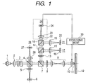
- reference numeral 1 denotes a semiconductor laser
- 2 is a collimator lens
- 3 is a beam shaping prism
- 4 is an NBS
- 5 , 15 , 19 and 26 are lenses
- 6 is an LPC-PD
- 7 is a PBS
- 8 is a QWP
- 9 is an expander lens
- 10 is an objective lens
- 11 is an SIL
- 12 is a dual-layer disc
- 13 is an HWP
- 14 is a PBS
- 16 is a PD 1
- 17 is an RF output
- 18 is an NBS
- 20 is a PD 2
- 21 is a tracking error
- 27 is a PD 3
- 28 is a gap error.
- a light flux that is output from a semiconductor laser 1 having a wavelength of 405 nm is converted into a collimated light flux by a collimator lens 2 , and then input to a beam shaping prism 3 to provide an isotropic light quantity distribution.
- the light flux that is transmitted by the polarization beam splitter (PBS) 7 through a non-polarization beam splitter (NBS) 4 passes through a 1 ⁇ 4 wavelength plate (QWP) 8 , and is converted into a circularly polarized light from a linearly polarized light.
- the photodetector (LPC-PD) 6 receives the light flux that has been reflected by the non-polarization beam splitter (NBS) 4 , and controls the output power of the semiconductor laser 1 .
- the light flux that has been transmitted by the 1 ⁇ 4 wavelength plate 8 is input to the expander lens 9 .
- the expander lens 9 corrects spherical aberration that occurs in an objective lens or an SIL which will be described later.
- the expander lens 9 is so adapted as to control an interval between two lenses according to the spherical aberration.
- the light flux from the expander lens 9 is input to the objective lens (rear lens 10 ).
- An objective lens unit includes the objective lens (rear lens) 10 and the SIL (front lens) 11 .
- the objective lens 10 and the SIL (front lens) 11 are held by a lens holder as will be described later.
- the lens holder is mounted on a 2-axis actuator (not shown) that drives two lenses integrally in a focus direction and in a tracking direction.
- the SIL 11 is of two types shown in FIGS. 20 and 21 .
- a light flux that has been focused by an objective lens (rear lens) 101 is collected on a bottom surface of a hemispherical lens SIL 102 - a .
- the light flux is input perpendicularly to the spherical surface of the hemispherical lens, and then collected on the bottom surface through the same optical path as that in the case where there is no hemispherical lens.
- the wavelength is equivalently shortened by the refractive index of the hemispherical lens, and therefore the optical spot diameter is reduced.
- the refractive index of the hemispherical lens is N
- the numeric aperture of the objective lens 101 is NA
- a light spot corresponding to N ⁇ NA is obtained on the recording surface of the optical disc 103 .
- An error of about 10 ⁇ m in the thickness of the hemispherical lens 102 - a can be allowed, so the mass production is facilitated.
- a light flux that has been focused by the objective lens (rear lens) 101 is collected on a bottom surface of an super-hemispherical lens SIL 102 - b .
- the bottom surface is spaced apart from the center of the super-hemispherical lens SIL 102 - b by R/N.
- the light spot corresponding to N 2 ⁇ NA is obtained on the recording surface of the optical disc 103 , taking the fact that the light flux is collected in the SIL of the refractive index N into account.
- the NA of the objective lens 101 is limited to 1/N or lower through Expression (1) under the condition where the light flux can be input to SIL 102 - b.
- NA 0.5
- NAeff 0.5
- an error in the thickness of the super-hemispherical lens 102 - b cannot be allowed to be higher than about 1 ⁇ m.
- the distance between the bottom surface of the SIL and the optical disc 103 is a short distance that is equal to or less than a fraction of divers of the wavelength 405 nm of the light source, for example, 100 nm or less
- the light spot affects the recording surface from the bottom of SIL as an evanescent light, and recording/reproduction can be conducted by the light spot diameter of NAeff.
- a gap servo is employed.
- the optical disc 12 of FIG. 19 is formed of a dual-layer disc having two recording layers which will be described later with reference to FIGS. 22 and 23 .
- the light flux that has been reflected by the dual-layer disc 12 becomes a circularly polarized light that is inversely rotated, and is input to the SIL 11 and the objective lens 10 , and again converted into a collimated light flux.
- the light flux that has passed through the expander lens 9 and the 1 ⁇ 4 wavelength plate 8 and has been linearly polarized in a direction orthogonal to the going path is reflected by the PBS 7 , and then input to the 1 ⁇ 2 wavelength plate (HWP) 13 .
- HWP 1 ⁇ 2 wavelength plate
- an S polarized light component in the light flux whose polarization plane is rotated by 45° by the 1 ⁇ 2 wavelength plate (HWP) 13 is reflected by the polarization beam splitter 14 , and then collected on the photodetector (PD 1 ) 16 through the lens 15 .
- Information on the optical disc 12 is reproduced from the RF output 17 of the photodetector (PD 1 ) 16 .
- a P polarized light component in the light flux whose polarization plane is rotated by 45° by the 1 ⁇ 2 wavelength plate (HWP) 13 is transmitted by the polarization beam splitter 14 , reflected by the non-polarization beam splitter (NBS) 18 , and then collected on the two-division photodetector (PD 2 ) 20 through the lens 19
- a tracking error 21 is obtained from an output signal of the two-division photodetector (PD 2 ) 20 .
- the light flux of NAeff ⁇ 1 that does not conduct total reflection among the light flux that is reflected by the bottom surface of SIL 11 is reflected as the circularly polarized light that rotates inversely to the input light as with the reflected light from the double-layer optical disc 12 .
- the light flux of NAeff ⁇ 1 which occurs total reflection produces a phase difference ⁇ which is represented by the following expression (2) between the P polarized light component and the S polarized light component, and forms an elliptically polarized light that is deviated from the circularly polarized light.
- tan( ⁇ /2) cos ⁇ i ⁇ ( N 2 ⁇ sin 2 ⁇ i ⁇ 1)/( N ⁇ sin 2 ⁇ i ) (2)
- the light flux when the light flux passes through the 1 ⁇ 4 wavelength plate 8 , the light flux includes the polarized light component in the same direction as the going path.
- the polarized light component is transmitted by the PBS 7 , reflected by the NBS 4 , and collected on the photodetector (PD 3 ) 27 through the lens 26 .
- the amount of light flux is monotonically more reduced as the distance between the bottom surface of the SIL and the dual-layer disc is shorter in the near field region, and therefore the polarized light component can be used as the gap error signal 28 .
- the gap servo is conducted such that the distance between the bottom surface of the SIL and the optical disc can be held to a desired distance of 100 nm or less.
- the gap servo is disclosed in detail in the above-mentioned article of Japan journal applied physics, vol. 44 (2005), pp. 3564 to 3567. Further, since the light flux is not modulated by the recording information on the optical disc 12 , a stable gap error signal can be obtained regardless of the presence or absence of the recording information.
- recording of 84 GB can be conducted on the disc that is 120 mm in diameter.
- the refractive index of the protective layer that protects the recording layer can be selected to be about 1.6, it is possible to use the protective layer made of an inexpensive organic material.
- a manufacture error of the hemispherical SIL is relatively so lax as to allow mass production. The comparison of those SIL is disclosed in detail in the above-mentioned article of Optical data storage 2004, proceedings of SPIE vol. 5380 (2004).
- the dual-layer disc 12 has an L 0 recording layer 12 - 2 disposed on a polycarbonate substrate 12 - 1 .
- the L 0 recording layer 12 - 2 has an information track and a track along which pits are defined.
- an L 1 recording layer 12 - 4 having an information track and a track along which pits are formed through, for example, an intermediate layer 12 - 3 having a constant thickness of 3 ⁇ m which is made of 2P (photo polymer), likewise.
- a cover layer 12 - 5 having a constant thickness of 3 ⁇ m which is made of 2P (photo polymer).
- the center of a sphere of a virtual hemispherical SIL 11 (the center of a circle indicated by a dotted line) is located substantially at the intermediate between the L 0 recording layer 12 - 2 and the L 1 recording layer 12 - 4 .
- an interval between the objective lens 10 and the SIL 11 is adjusted to d 1 by a voice coil motor 201 as shown in FIG. 22 .
- the light flux that has been collimated by the expander lens 9 passes through the objective lens 10 and the SIL 11 , and is focused on the L 0 recording layer that is located at a position slightly farther from the SIL than the virtual center of the above-mentioned sphere.
- the interval between the objective lens 10 and the SIL 11 is adjusted to d 2 (d 2 >d 1 ) by the voice coil motor 201 , as shown in FIG. 23 .
- the light flux that has been collimated by the expander lens 9 passes through the objective lens 10 and the SIL 11 , and is focused on the L 1 recording layer 12 - 4 that is located at a position slightly closer from the SIL than the virtual center of the above-mentioned sphere.
- Jump of the interlayer between the L 0 recording layer and the L 1 recording layer of the optical disc is conducted by controlling the objective lens 10 by the voice coil motor 201 and adjusting the interval between the objective lens 10 and the SIL 11 , as shown in FIG. 23 .
- This technique is disclosed in detail in the above-mentioned article of Optical data storage 2004, proceedings of SPIE vol. 5380 (2004).
- the voice coil motor 201 that adjusts the interval between the objective lens 10 and the lens SIL 11 is mounted on a lens holder 202 .
- the lens holder 202 is controlled such that the distance between the SIL 11 and the disc 12 is kept to a given value by a 2-axis actuator (not shown) according to the gap error signal 28 . Further, the lens holder 202 is controlled such that the light spot tracks a desired track by the 2-axis actuator according to a tracking error signal 21 .
- the conventional optical information recording/reproducing apparatus for near field recording using the hemispherical SIL 11 and the dual-layer disc 12 suffers from the following problems. That is, the distance between the SIL and the disc is merely kept to a desired value according to the gap error signal. Therefore, in order to focus the light flux on the L 0 layer or the L 1 layer with precision, the focus error signal cannot be used, and it is necessary to always monitor the amplitude or the modulation degree of the tracking error signal or the RF signal. This is because the reflected light from the bottom surface of the SIL 11 is mixed with the focus error signal as a noise as described above.
- the light spot is incapable of tracking the unevenness rapidly, thereby making it difficult to record or reproduce information with precision.
- the wavelength of the semiconductor laser changes due to a temperature change, the light flux is incapable of tracking the change of the wavelength quickly, thereby making it difficult to record or reproduce information with precision.
- an object of the present invention is to provide an optical information recording/reproducing apparatus which is capable of preventing a reflected light from the bottom surface of an SIL from being mixed with a light flux that detects a focus error as a noise, to thereby focus the light flux on the basis of a focus error signal.
- the focus error signal is detected from the reflected light flux from a recording layer of an optical recording medium, and the light flux is focused on the recording layer of the optical recording medium on the basis of the focus error signal.
- the light flux of the effective numeric aperture NAeff ⁇ 1 due to an objective lens and the SIL within a pupil is detected by a splitting device as the focus error signal.
- FIG. 1 is a structural diagram illustrating an optical information recording/reproducing apparatus according to Embodiment 1 of the present invention.
- FIG. 2 is a diagram illustrating optical means for detecting a focus error signal according to the embodiment shown in FIG. 1 in detail.
- FIG. 3 is a diagram schematically illustrating the light quantity distribution within a pupil according to the embodiment shown in FIG. 1 .
- FIG. 4 is a structural diagram illustrating Embodiment 2 of the present invention.
- FIG. 5 is a diagram for explaining Embodiment 3 of the present invention.
- FIG. 6 is a diagram for explaining a focus error that is obtained by a dual-layer disc according to the present invention.
- FIG. 7 is a diagram for explaining spherical aberration correction of a liquid crystal device according to the present invention.
- FIGS. 8A and 8B are diagrams for explaining an electrode of the liquid crystal device according to the present invention.
- FIG. 9 is a diagram for explaining an optical information recording/reproducing apparatus for near field recording according to Embodiment 4 of the present invention.
- FIG. 10 is a diagram illustrating a focus error signal that is obtained by a dual-layer disc shown in FIG. 1 .
- FIG. 11 is a diagram illustrating Embodiment 6 of the present invention.
- FIG. 12 is a diagram illustrating Embodiment 7 of the present invention.
- FIG. 13 is a diagram for explaining the pattern of a hologram according to Embodiment 7 of the present invention.
- FIG. 14 is a diagram illustrating Embodiment 8 of the present invention.
- FIG. 15 is a diagram for explaining the arrangement of GEPD according to the Embodiment 8 of the present invention.
- FIG. 16 is a diagram illustrating Embodiment 9 of the present invention.
- FIG. 17 is a diagram illustrating a configuration of an S curve that is obtained by a focus error detecting optical system according to Embodiment 10 of the present invention.
- FIG. 18 is a diagram illustrating a configuration of the S curve in the vicinity of focusing on a first layer and a second layer.
- FIG. 19 is a structural diagram illustrating an optical information recording/reproducing apparatus for near field recording in a conventional example.
- FIG. 20 is a diagram for explaining a hemispherical SIL in a conventional example.
- FIG. 21 is a diagram for explaining an super-hemispherical SIL in the conventional example.
- FIG. 22 is a diagram illustrating a case in which a light flux is focused on an L 0 recording layer of a dual-layer disc in the conventional example.
- FIG. 23 is a diagram illustrating a case in which a light flux is focused on an L 1 recording layer of the dual-layer disc in the conventional example.
- FIG. 24 is a structural diagram illustrating an optical information recording/reproducing apparatus according to Embodiment 5 of the present invention.
- FIG. 1 illustrates the configuration of an optical pickup for near field recording in an optical information recording/reproducing apparatus according to the present invention.
- FIG. 1 the same parts as those in the conventional apparatus are denoted by identical symbols.
- FIG. 1 shows a focus servo control circuit 30 , and a recording circuit and a reproducing circuit which are required to record or reproduce information on an optical disc, a servo control circuit, and a circuit and a mechanism that conduct seek control of an optical pickup are not shown in FIG. 1 . Further, other circuits and mechanisms such as a motor that rotationally drives the optical disc and a controller that controls the respective parts within the apparatus are also not shown in FIG. 1 .
- a light flux that is output from a semiconductor laser 1 having a wavelength of 405 nm is converted into a collimated light flux by a collimator lens 2 , and input to the beam shaping prism 3 to provide an isotropic light quantity distribution.
- the light flux that has been transmitted by the polarization beam splitter (PBS) 7 through the non-polarization beam splitter (NBS) 4 passes through the 1 ⁇ 4 wavelength plate (QWP) 8 , and is then converted into a circularly polarized light from the linearly polarized light.
- a photodetector (LPC-PD) 6 for receiving a light flux that has been reflected by the non-polarization beam splitter (NBS) 4 to control the output power of the semiconductor laser 1 .
- the light flux that has passed through the 1 ⁇ 4 wavelength plate (QWP) 8 is input to the expander lens 9 .
- the expander lens 9 is adapted to correct the spherical aberration that occurs in the objective lens or the SIL so as to control the interval between those two lenses according to the spherical aberration.
- the light flux from the expander lens 9 is input to the objective lens 10 .
- the objective lens (rear lens) 10 and the SIL (front lens) 11 are held by the lens holder 202 as described with reference to FIGS. 22 and 23 .
- the lens holder 202 is mounted on the 2-axis actuator that integrally drives the two lenses in the focus direction and in the tracking direction. Further, the voice coil motor 201 is held by the lens holder 202 , and the objective lens 10 is moved in the focus direction by driving the voice coil motor 201 .
- the SIL is of the hemispherical type shown in FIG. 20 .
- the distance between the bottom surface of the SIL and the optical disc 12 is a short distance that is equal to or less than a fraction of divers of the wavelength 405 nm of the light source, for example, 100 nm or less, the light spot affects the recording surface from the bottom of SIL as an evanescent light, and recording or reproduction can be conducted with the light spot diameter of NAeff.
- a gap servo is employed.
- the dual-layer disc 12 is formed of a dual-layer disc having two recording layers as shown in FIGS. 22 and 23 .
- the light flux that has been reflected by the optical disc 12 becomes a circularly polarized light that is inversely rotated, and is input to the SIL 11 and the objective lens 10 , and again converted into a collimated light flux.
- the light flux that has passed through the expander lens 9 and the 1 ⁇ 4 wavelength plate 8 and has been linearly polarized in a direction orthogonal to the going path is reflected by the PBS 7 , and then input to the 1 ⁇ 2 wavelength plate (HWP) 13 .
- An S polarized light component in the light flux whose polarization plane is rotated by 45° by the 1 ⁇ 2 wavelength plate (HWP) 13 is reflected by the polarization beam splitter 14 , and then collected on the photodetector (PD 1 ) 16 through the lens 15 .
- Information on the optical disc 12 is reproduced from the RF output 17 of the photodetector (PD 1 ) 16 .
- a P polarized light component in the light flux whose polarization plane is rotated by 45° by the 1 ⁇ 2 wavelength plate (HWP) 13 is transmitted by the polarization beam splitter 14 , reflected by the non-polarization beam splitter (NBS) 18 , and then collected on the two-division photodetector (PD 2 ) 20 through the lens 19 .
- a tracking error 21 is obtained from an output signal of the two-division photodetector (PD 2 ) 20 .
- the configuration is surrounded by a dotted line of FIG. 1 . That is, the light flux that has passed through the non-polarization beam splitter 18 passes through an aperture 22 , and an outer peripheral portion of the light flux is shielded from light Then, the light flux passes through a sensor lens 23 , and is collected on the photodetector (PD 4 ) 24 . A focus error 25 is obtained from the output of the photodetector (PD 4 ) 24 .
- the sensor lens 23 is, for example, a toric lens.
- the focus error 25 is obtained according to the output signal from the photodetector (PD 4 ) 24 that is a quadrant photodetector through a known astigmatism method, and the light flux is focused on a desired recording layer by a focus servo control circuit 30 .
- FIG. 2 shows the configuration surrounded by the dotted line shown in FIG. 1 in detail.
- the same symbols as those of FIG. 1 denote identical members with those of FIG. 1 .
- the same is applied to the following figures.
- the sensor lens 23 is a toric lens as described above, and the light flux is focused on a desired recording layer according to the output signal from the quadrant photodetector 24 through the astigmatism method.
- FIG. 3 schematically shows the light quantity distribution within the pupil.
- FIG. 3 shows a case in which the distance between the SIL and the optical disc is held to a distance that is equal to or less than a fraction of divers of the wavelength 405 nm, for example, 50 nm or less, by the gap servo.
- the annular portion of NA>1 contains a large quantity of reflected light from the bottom surface of the SIL, which is a noise of the focus signal.
- the aperture 22 allows the light flux of NA ⁇ 1 or lower, for example, NA ⁇ 0.85 which is an inside of the dotted line of FIG. 3 to be transmitted.
- the light flux of NA ⁇ 1 or lower contains a large quantity of reflected light from the recording layer of the optical disc 12 , thereby enabling focus information to be easily obtained.
- NA is an effective numerical aperture of the objective lens 10 and the SIL 11 .
- the objective lens 10 and the SIL (front lens) 11 are held by the lens holder 202 as in FIGS. 22 and 23 , and the voice coil motor 201 that adjusts the interval between both the lenses is held on the lens holder 202 .
- the lens holder 202 is adapted to move in the focus direction and the tracking direction by driving a 2-axis actuator (not shown), likewise.
- a gap servo circuit (not shown) controls the 2-axis actuator on the basis of the gap error signal 28 as in FIG. 19 , to thereby hold the interval between the SIL 11 and the optical disc 12 to a given value The gap servo will be described later.
- the tracking servo circuit (not shown) controls the 2-axis actuator on the basis of the tracking error signal 21 , to thereby scan an intended information track with a fine light spot from the semiconductor laser 1 under the control
- the voice coil motor 201 is controlled to move the objective lens 10 in the optical axial direction, to thereby conduct the interlayer jump between the L 0 recording layer and the L 1 recording layer.
- the interlayer jump is conducted under the control by a controller (not shown).
- the focus servo is conducted in the same manner as that in the conventional focus servo of the single-layer disc or the dual-layer disc.
- the focus error signal 25 is supplied to the focus servo circuit 30 , and the voice coil motor 201 is controlled by the focus servo circuit 30 . That is, the objective lens 10 is controlled in the focus direction by the focus servo circuit 30 such that the focus error signal becomes zero.
- the focus servo is conducted such that the fine light spot from the semiconductor laser 1 is focused on the L 0 recording layer or the L 1 recording layer of the optical disc 12 .
- the reflected light flux from the recording layer passes through the objective lens 10 and the SIL 11 , and is collimated by the expander lens 9 , and the position of the sensor lens 23 is adjusted in advance such that the focus error signal at that time becomes zero.
- the light flux is precisely focused on the L 0 recording layer or the L 1 recording layer of the optical disc according to the focus error signal, even if a slight thickness unevenness occurs in the cover layer or the intermediate layer of the optical disc, it is possible to follow the thickness unevenness rapidly, thereby enabling accurate information recording or reproduction. Further, even if the wavelength of the semiconductor laser 1 changes due to the temperature change, it is possible to follow the change in the wavelength rapidly, thereby enabling accurate information recording or reproduction.
- the focus error signal can be referred to, the rapid focus jump can be conducted, and no jump fails.
- the light flux of NAeff ⁇ 1 that does not conduct total reflection among the light flux that is reflected by the bottom surface of SIL 11 is reflected as the circularly polarized light that is inversely rotated to the input as with the reflected light from the optical disc 12 .
- the light flux of NAeff ⁇ 1 which occurs total reflection the light flux produces a phase difference ⁇ which is represented by Expression (2) between the P polarized light component and the S polarized light component of the reflected light, and forms an elliptically polarized light that is deviated from the circularly polarized light.
- the light flux contains the polarized light component in the same direction as with the going path after passing through the 1 ⁇ 4 wavelength plate 8 .
- the polarized light component is transmitted by the polarization beam splitter (PBS) 7 , reflected by the non-polarization beam splitter (NBS) 4 , and collected on the photodetector (PD 3 ) 27 through the lens 26 .
- the light quantity of the light flux is monotonously reduced more as the distance between the bottom surface of the SIL and the optical disc is shorter in the near field region, and therefore can be used as the gap error signal 28 .
- the 2-axis actuator is driven to conduct the gap servo, thereby enabling the distance between the bottom surface of the SIL and the optical disc to be held to a desired distance of 100 nm or less.
- the gap error signal 28 can be normalized according to the output of the photodetector (LPC-PD) 6 for controlling the output power of the semiconductor laser 1 .
- the aperture 22 split device for guiding the light flux of NAeff ⁇ 1 into the light receiving device is disposed.
- the influence is small in obtaining the focus error signal without deviating from the main features of the present invention. The same is applied to the following embodiments.
- FIG. 4 is a structural diagram showing Embodiment 2 of the present invention.
- the same parts as those of FIG. 1 are denoted by identical symbols.
- a focus servo control circuit 30 and a recording circuit and a reproducing circuit which are required to record or reproduce information on an optical disc, a servo control circuit, and a circuit and a mechanism that conduct seek control of an optical pickup are not shown in FIG. 4 .
- the focus servo circuit 30 is not shown in FIG. 4 .
- other circuits and mechanisms such as a motor that rotationally drives the optical disc and a controller that controls the respective parts within the apparatus are well known, and therefore are not shown in FIG. 4 .
- a light flux that is output from a semiconductor laser 1 having a wavelength of 405 nm is converted into a collimated light flux by a collimator lens 2 , and input to the beam shaping prism 3 to provide an isotropic light quantity distribution.
- the light flux that has been transmitted by the polarization beam splitter (PBS) 7 through the non-polarization beam splitter (NBS) 4 is input to the expander lens 9 .
- the expander lens 9 is adapted to correct the spherical aberration that occurs in the objective lens or the SIL so as to control the interval between those two lenses according to the spherical aberration.
- a photodetector (LPC-PD) 6 for receiving a light flux that has been reflected by the non-polarization beam splitter (NBS) 4 to control the output power of the semiconductor laser 1 .
- the light flux from the expander lens 9 is input to the objective lens 10 .
- the objective lens 10 and the SIL 11 are held by the lens holder, likewise.
- the lens holder is mounted on the 2-axis actuator (not shown) that integrally drives the two lenses in the focus direction and in the tracking direction.
- the SIL is of the hemispherical type shown in FIG. 20 .
- the distance between the bottom surface of the SIL and the optical disc 12 is a short distance that is equal to or less than a fraction of divers of the wavelength 405 nm of the light source, for example, 100 nm or less, the light spot affects the recording surface from the bottom of SIL as an evanescent light. Therefore, recording/reproduction can be conducted by the light spot diameter of NAeff.
- the above-mentioned gap servo is employed.
- the dual-layer disc 12 is formed of an optical disc having two recording layers as shown in FIGS. 22 and 23 .
- the light flux that has been reflected by the optical disc 12 is input to the SIL 11 and the objective lens 10 , and again converted into a collimated light flux.
- the light flux that has passed through the expander lens 9 and has been linearly polarized in a direction identical with the going path is transmitted by the PBS 7 , reflected by the NBS 4 , and then input to the 1 ⁇ 2 wavelength plate (HWP) 13 .
- An S polarized light component in the light flux whose polarization plane is rotated by 45° by the 1 ⁇ 2 wavelength plate (HWP) 13 is reflected by the polarization beam splitter 14 , and then collected on the photodetector (PD 1 ) 16 through the lens 15 .
- Information on the optical disc 12 is reproduced from the RF output 17 of the photodetector (PD 1 ) 16 .
- a P polarized light component in the light flux whose polarization plane is rotated by 45° by the 1 ⁇ 2 wavelength plate (HWP) 13 is transmitted by the polarization beam splitter 14 , reflected by the non-polarization beam splitter (NBS) 18 , and then collected on the two-division photodetector (PD 2 ) 20 through the lens 19
- a tracking error 21 is obtained from an output signal of the two-division photodetector (PD 2 ) 20 .
- the characteristic point of this embodiment resides in the configuration surrounded by the dotted line shown in FIG. 4 . That is, the light flux that has been transmitted by the non-polarization beam splitter 18 passes through the aperture 22 , and an outer peripheral portion (NA>1) of the light flux is shielded from light. Then, the light flux passes through the sensor lens 23 , and is collected on the photodetector (PD 4 ) 24 through the sensor lens 23 . The focus error 25 is obtained from the output signal of the photodetector (PD 4 ) 24 .
- the sensor lens 23 is, for example, a toric lens, and detects the focus error signal according to the output signal from the quadrant photodetector (PD 4 ) 24 through the known astigmatism method.
- the configuration surrounded by the dotted line is identical with that in Embodiment 1, and therefore their description will be omitted.
- the focus servo is conducted in the same manner as that in Embodiment 1.
- the focus error signal 25 is supplied to the focus servo circuit 30 , and the voice coil motor 201 is controlled by the focus servo circuit 30 . That is, the objective lens 10 is controlled in the focus direction by the focus servo circuit 30 such that the focus error signal becomes zero.
- the focus servo is conducted such that the fine light spot from the semiconductor laser 1 is focused on the L 0 recording layer or the L 1 recording layer of the optical disc 12 .
- Gap servo, the tracking servo, and the interlayer jump are identical with those in Embodiment 1, and therefore their detailed description will be omitted.
- the light flux is precisely focused on the L 0 recording layer or the L 1 recording layer of the optical disc according to the focus error signal, even if a slight thickness unevenness occurs in the cover layer or the intermediate layer of the optical disc, it is possible to follow the thickness unevenness rapidly, thereby enabling accurate information recording or reproduction. Further, even if the wavelength of the semiconductor laser 1 changes due to the temperature change, it is possible to follow the change in the wavelength rapidly, thereby enabling accurate information recording or reproduction.
- the focus error signal can be referred to, the rapid focus jump can be conducted, and no jump fails.
- the light flux of NAeff ⁇ 1 that does not conduct total reflection among the light flux that is reflected by the bottom surface of SIL 11 is reflected as the linearly polarized light that is substantially the same as that at the time of inputting the light flux as with the reflected light from the optical disc 12 .
- the light flux that is input to the bottom of the SIL at an azimuth other than the input polarization direction and a direction orthogonal to the input polarization direction produces a phase difference ⁇ which is represented by Expression (2) between the P polarized light component and the S polarized light component of the reflected light, and forms an elliptically polarized light that is deviated from the circularly polarized light.
- the light flux contains the polarized light component in the direction orthogonal to the going path.
- the polarized light component is reflected by the PBS 7 and collected on the photodetector (PD 3 ) 27 through the lens 26 .
- the light quantity of the light flux is monotonously reduced more as the distance between the bottom surface of the SIL and the optical disc is shorter in the near field region, and therefore can be used as the gap error signal 28 .
- the 2-axis actuator is driven to conduct the gap servo, thereby enabling the distance between the bottom surface of the SIL and the optical disc to be held to a desired distance of 100 nm or less.
- the gap error signal 28 can be normalized according to the output of the photodetector (LPC-PD) 6 for controlling the output power of the semiconductor laser 1 .
- the double-layer recording medium having the two recording layers is used.
- the present invention is not limited to the above configuration, but is applicable to a recording medium having one recording layer or a recording medium having two or more recording layers.
- This embodiment provides an optical information recording/reproducing apparatus that is capable of precisely focusing the light flux on the double-layer optical disc according to the focus error signal, and also is capable of correcting the spherical aberration at the same time so as to enable the rapid and stable interlayer jumping operation.
- FIG. 5 is a diagram for explaining the configuration of the optical information recording/reproducing apparatus for near field recording according to the present invention.
- a light flux that is output from a semiconductor laser 1 having a wavelength of 405 nm is converted into a collimated light flux by the collimator lens 2 , and input to the beam shaping prism 3 to provide an isotropic light quantity distribution.
- the light flux that has been transmitted by the polarization beam splitter (PBS) 7 through the non-polarization beam splitter (NBS) 4 is input to the expander lens 9 .
- a photodetector (LPC-PD) 6 for receiving a light flux that has been reflected by the non-polarization beam splitter (NBS) 4 to control the output power of the semiconductor laser 1 .
- the expander lens 9 is so adapted as to control the interval between those two lenses according to the focus error 25 that will be described later.
- the light flux from the expander lens passes through the liquid crystal device 29 and the 1 ⁇ 4 wavelength plate (QWP) 8 , and is converted into the circularly polarized light from the linearly polarized light.
- a voltage is applied to the liquid crystal device 29 so as to generate the inverse phase of the spherical aberration that occurs at the respective focal positions of the dual-layer disc 12 as will be described later.
- the light flux that has been transmitted by the 1 ⁇ 4 wavelength plate is inputted to the rear lens 10 of the objective lens.
- An objective lens unit includes the objective lens (rear lens) 10 and the SIL (front lens) 11 .
- the objective lens 10 and the SIL (front lens) 11 are mounted on a 2-axis actuator (not shown) that drives two lenses integrally in a focus direction and in a tracking direction, together with the liquid crystal device 29 and the 1 ⁇ 4 wavelength plate 8 .
- the SIL is of the hemispherical type described with reference to FIG. 20 .
- a focusing method according to one of the characteristics of the present invention is identical with the portion surrounded by the dotted line of FIG. 1 which is described in Embodiment 1 and the contents described with reference to FIGS. 2 and 3 , and its description will be omitted.
- the focus error signal 25 allows the interval between two lenses of the expander lens 9 to be changed under the gap servo, to thereby obtain a signal shown in FIG. 6 in correspondence with the L 0 layer and the L 1 layer. Therefore, in conducting the interlayer jump, the interval between the two lenses of the expander lens 9 is changed with reference to the focus error 25 to move between the focal position of the L 0 layer and the focal position of the L 1 layer.
- FIG. 7 is an explanatory diagram showing a case in which the spherical aberration is corrected by the liquid crystal device, and schematically shows the appearance of correction.
- An axis of abscissa of FIG. 7 represents a radius of a standardized light flux, and an axis of ordinate represents the spherical aberration quantity.
- a dotted line represents the spherical aberration before correction
- a broken line represents the spherical aberration to be corrected
- a solid line represents after the correction.
- the spherical aberration is corrected by using the liquid crystal device, thereby enabling the spherical aberration to be reduced.
- FIG. 8A is a schematic diagram showing the electrode of the liquid crystal device used in FIG. 7
- FIG. 8B is a schematic diagram showing the correction quantity of the spherical aberration in the liquid crystal device.
- FIGS. 8A and 8B show the electrode of the liquid crystal device which conducts the aberration correction of eight divisions at five stages as an example. However, the number of stages and the number of divisions are not limited to this embodiment.
- the voltage across the electrode of the liquid crystal device is controlled to generate the inverse phases of the spherical aberration quantities which are generated in the optical system of the optical information recording/reproducing apparatus for near field recording at the focal position of the L 0 layer and the focal position of the L 1 layer in the near liquid crystal, respectively.
- the spherical aberrations are corrected at the focal positions of the respective layers.
- the configuration can be simplified in such a manner that the spherical aberration quantities that are generated in the liquid crystal device at the focal position of the L 0 layer and the focal position of the L 1 layer have two values that are identical in absolute value with each other and different in sign from each other, and the symbols are merely changed over.
- the light flux of NAeff ⁇ 1 that does not conduct total reflection among the light flux that is reflected by the bottom surface of SIL 11 is reflected as the circularly polarized light that rotates inversely to the input light as with the reflected light from the optical disc 12 .
- the light flux of NAeff ⁇ 1 which causes total reflection produces a phase difference ⁇ which is represented by Expression (2) between the P polarized light component and the S polarized light component, and forms an elliptically polarized light that is deviated from the circularly polarized light.
- the light flux passes through the 1 ⁇ 4 wavelength plate 8 , the light flux contains the polarized light component in the same direction as that of the going path.
- the polarized light component is transmitted by the PBS 7 and reflected by the NBS 4 , and collected on the photodetector (PD 3 ) 27 through the lens 26 .
- the light quantity of the light flux is monotonously reduced more as the distance between the bottom surface of the SIL and the optical disc is shorter in the near field region, and therefore can be used as the gap error signal 28 .
- the 2-axis actuator is driven to conduct the gap servo, thereby enabling the distance between the bottom surface of the SIL and the optical disc to be held to a desired distance of 100 nm or less.
- the gap error signal 28 can be normalized according to the output of the photodetector (LPC-PD) 6 for controlling the output power of the semiconductor laser 1 .
- the focus error signal can be used in order to precisely focus the light flux on the L 0 recording layer or the L 1 recording layer, even if a slight thickness unevenness occurs in the cover layer or the intermediate layer, it is possible to follow the thickness unevenness rapidly by the lens interval variable drive of the expander lens.
- the spherical aberration is corrected by the liquid crystal device, it is possible to conduct the accurate information recording or reproduction.
- the spherical aberration generated on the basis of the controlling may be also corrected by the liquid crystal device.
- the spherical aberration quantities on the basis of the controlling is unknown, it is necessary to provide a detection system which optically detects the spherical aberration quantities, thereby enabling accurate information recording or reproduction.
- the focus error signal can be referred to, focusing is conducted by the lens interval variable drive of the expander lens, and at the same time, the spherical aberration is corrected under the control of the voltage that is applied to the liquid crystal device. For that reason, there can be provided an apparatus which is capable of conducting the rapid and stable focus jump and has the excellent recording/reproducing characteristic.
- reference numeral 31 denotes a semiconductor laser
- 32 is an NBS
- 33 is an LPC-PD
- 34 is a PBS
- 35 is a QWP
- 36 is an expander lens
- 37 is a mirror
- 38 is an objective lens
- 39 is an SIL
- 40 is a dual-layer disc
- 41 is a hologram
- 42 is a lens
- 43 is a PD
- 44 is a PD
- 45 is a focus error
- 46 is a tracking error
- 47 is an RF output
- 48 is a gap error
- 49 is a liquid crystal device.
- a light flux that has been output from the semiconductor laser 31 having a wavelength of 405 nm is input to the polarization beam splitter (PBS) 34 through the non-polarization beam splitter (NBS) 32 .
- the photodetector (LPC-PD) 33 for receiving a light flux that has been reflected by the non-polarization beam splitter (NBS) 32 to control the output power of the semiconductor laser 31 .
- the light flux that has been transmitted by the polarization beam splitter (PBS) 34 is inputted to the expander lens 36 .
- the expander lens 36 is so adapted as to control the interval between those two lens groups according to the focus error 45 that will be described later.
- the expander lens 36 also has a collimator function that substantially collimates the light flux.
- the light flux from the expander lens 36 is transmitted by the liquid crystal device 49 , and then input to the 1 ⁇ 4 wavelength plate (QWP) 35 .
- the light flux that has been transmitted by the 1 ⁇ 4 wavelength plate (QWP) 35 is converted into the circularly polarized light from the linearly polarized light, and then input to the rear lens 38 of the objective lens.
- the objective lens includes the rear lens 38 and the SIL (front lens) 39 .
- the rear lens 38 and the SIL (front lens) 39 are mounted on a 2-axis actuator (not shown) that drives those two lenses integrally in a focus direction and in a tracking direction.
- the SIL is of the hemispherical type described with reference to FIG. 20 .
- the distance between the bottom surface of the SIL and the optical disc 40 is a short distance that is equal to or less than a fraction of divers of the wavelength 405 nm of the light source, for example, 100 nm or less, the light spot affects the recording surface from the bottom of the SIL as an evanescent light. Therefore, recording/reproduction can be conducted by the light spot diameter of NAeff.
- the above-mentioned gap servo is employed as in Embodiment 1.
- the optical disc 40 is a dual-layer disc having two recording layers.
- the light flux that has been reflected by the optical disc 40 is converted into a circularly polarized light that is inversely rotated, input to the SIL 39 and the objective lens 38 , and again converted into a collimated light flux.
- the light flux that has passed through the 1 ⁇ 4 wavelength plate 35 , the liquid crystal device 49 , and the expander lens 36 and has been linearly polarized in a direction orthogonal to the return path is reflected by the PBS 34 .
- the reflected light flux is divided into a light flux of NA ⁇ 1 and a light flux in the periphery of the former light flux by the hologram 41 , and input to the photodetector (PD) 43 .
- the focus error 45 is outputted by the light flux of NA ⁇ 1
- the tracking error 46 and the RF output 47 are outputted by the light flux in the periphery of the former light flux.
- the light flux that has been transmitted by the PBS 34 and reflected by the non-polarization beam splitter (NBS) 32 is inputted to the photodetector (PD) 44 to output the gap error 48 .
- the gap control method is identical with that in the above-mentioned Embodiment 1.
- the interval between those two lens groups of the expander lens 36 are controlled according to the focus error 45 , the light flux is focused on the desired recording layer, and the spherical aberration is corrected by the voltage control of the liquid crystal device 49 . For that reason, in conducting the interlayer jump, the interval between the two lens groups of the expander lens 36 and the applied voltage of the liquid crystal device 49 are changed to move between the focal position of the L 0 layer and the focal position of the L 1 layer as in Embodiment 1.
- the focus error signal can be used in order to precisely focus the light flux on the L 0 recording layer or the L 1 recording layer.
- the lens interval variable drive of the expander lens and the control of the voltage that is applied to the liquid crystal device.
- the precise information recording or reproduction can be performed.
- the spherical aberration generated on the basis of the controlling may be also corrected by the liquid crystal device.
- the spherical aberration quantities on the basis of the controlling is unknown, it is necessary to provide a detection system which optically detects the spherical aberration quantities, thereby enabling accurate information recording or reproduction.
- the rapid and stable focus jumping operation can be conducted by the lens interval variable drive of the expander lens and the control of the voltage that is applied to the liquid crystal device. As a result, there can be provided an apparatus having an excellent recording/reproduction characteristic.
- the expander lens 36 has a collimator function that substantially collimates the light flux
- the PBS or the NBS can be disposed between the semiconductor laser and the expander lens, which is useful in downsizing the apparatus.
- FIG. 24 is a diagram showing the configuration of an optical pickup for near field recording in an optical information recording/reproducing apparatus according to the present invention. Further, a recording circuit and a reproducing circuit, which are required to record or reproduce information on an optical disc, a servo control circuit (including the focus servo circuit 30 ), and a circuit and a mechanism that conduct seek control of an optical pickup are not shown in FIG. 24 . Further, the focus servo circuit 30 is not shown in FIG. 24 . Further, other circuits and mechanisms such as a motor that rotationally drives the optical disc and a controller that controls the respective parts within the apparatus are not also shown in FIG. 24 .
- a light flux that has been output from a semiconductor laser 1 having a wavelength of 405 nm is converted into a collimated light flux by the collimator lens 2 , and input to the beam shaping prism 3 to provide an isotropic light quantity distribution. Further, the light flux that has been transmitted by the polarization beam splitter (PBS) 7 through the non-polarization beam splitter (NBS) 4 passes through the 1 ⁇ 4 waveform plate (QWP) 8 , and is converted into the circularly polarized light from the linearly polarized light.
- PBS polarization beam splitter
- NBS non-polarization beam splitter
- a photodetector (LPC-PD) 6 for receiving a light flux that has been reflected by the non-polarization beam splitter (NBS) 4 to control the output power of the semiconductor laser 1 .
- the light flux that has been transmitted by the 1 ⁇ 4 wavelength plate (QWP) 8 is input to the expander lens 56 .
- the expander lens 56 is so adapted as to control the interval between those two lenses according to the focus error 25 that will be described later.
- the spherical aberration that occurs in the objective lens 10 and the SIL 11 is corrected in advance when the objective lens (rear lens) 10 and the SIL (front lens) 11 are assembled integrally.
- the light flux from the expander lens 9 is input to the objective lens 10 .
- the light flux that has been transmitted by the non-polarization beam splitter (NBS) 18 passes through the aperture 22 , and an outer peripheral portion of the light flux is shielded from light. Then, the light flux passes through the sensor lens 23 , and is collected on the photodetector (PD 4 ) 24 .
- the focus error 25 is obtained from the output of the photodetector (PD 4 ) 24 , and the interval between the two lenses of the expander lens 56 is controlled according to the focus error 25 to focus the light flux on a desired recording layer.
- the NA is the effective numerical aperture of the objective lens 10 and the SIL 11 .
- the sensor lens 23 is a toric lens, and the light flux is focused on a desired recording layer according to the output signal from the photodetector (PD 4 ) 24 that is a quadrant photodetector through the known astigmatism method
- the expander lens 56 has a structure in which one of the lenses is movable in the optical axis direction.
- the drive source such as an electromagnetic actuator
- the one of the lenses can be moved in the optical axis direction by a guide mechanism for guiding the lens in the optical axis direction. In this manner, by making the lens interval of the expander lens 56 , the focus servo and the interlayer jump are conducted.
- the focus servo circuit 30 conducts the focus servo such that the fine light spot from the semiconductor laser 1 is focused on the L 0 recording layer or the L 1 recording layer of the optical disc 12 on the basis of the focus error signal.
- FIG. 3 schematically shows the light quantity distribution within the pupil.
- FIG. 3 shows a case in which the distance between the SIL and the optical disc is held to a distance that is equal to or less than a fraction of divers of the wavelength 405 nm, for example, 50 nm by the gap servo.
- the annular portion of NA>1 contains a large quantity of reflected light from the bottom surface of the SIL, which is a noise of the focus signal.
- the aperture 22 allows the light flux of NA ⁇ 1 or lower, for example, NA ⁇ 0.85 which is an inside of the dotted line to be transmitted.
- the light flux of NA ⁇ 1 or lower contains a large quantity of reflected light from the recording layer of the optical disc 12 , thereby enabling focus information to be easily obtained.
- FIG. 10 illustrates a focus error signal 25 in the case where the lens interval of the expander lens 9 is variable.
- the focus error signal 25 allows the interval between the two lenses of the expander lens 56 to be changed under the gap servo.
- the focus error signal changes in correspondence with the L 0 recording layer and the L 1 recording layer as shown in FIG. 10 , and the focusing positions (focal positions) at the respective recording layers are found.
- a controller not shown monitors the focus error signal 25 shown in FIG. 10 while changing the interval between the two lenses of the expander lens 56 , and conducts the interlayer jump between the focal position of the L 0 recording layer and the focal position of the L 1 recording layer. With the above-mentioned operation, it is possible to conduct the interlayer jump rapidly and accurately.
- the light flux of NAeff ⁇ 1 that does not conduct total reflection among the light flux that is reflected by the bottom surface of SIL 11 is reflected as the circularly polarized light that rotates inversely to the input light as with the reflected light from the optical disc 12 .
- the light flux of NAeff ⁇ 1 which occurs total reflection produces a phase difference ⁇ which is represented by Expression (2) between the P polarized light component and the S polarized light component, and forms an elliptically polarized light that is deviated from the circularly polarized light.
- the light flux passes through the 1 ⁇ 4 wavelength plate 8 , the light flux contains the polarized light component in the same direction as that of the going path.
- the polarized light component is transmitted by the polarization beam splitter (PBS) 7 , reflected by the non-polarization beam splitter (NBS) 4 , and collected on the photodetector (PD 3 ) 27 through the lens 26 .
- the light quantity of the light flux is monotonously reduced more as the distance between the bottom surface of the SIL and the optical disc is shorter in the near field region, and therefore can be used as the gap error signal 28 .
- the 2-axis actuator is driven to conduct the gap servo, thereby enabling the distance between the bottom surface of the SIL and the optical disc to be held to a desired distance of 100 nm or less.
- the gap error signal 28 can be normalized according to the output of the photodetector (LPC-PD) 6 for controlling the output power of the semiconductor laser 1 .
- the gap servo is not shown in FIG. 1 , but is conducted by a gap servo circuit.
- the light flux can be precisely focused on the L 0 recording layer or the L 1 recording layer of the optical disc according to the focus error signal. For that reason, even if a slight thickness unevenness occurs in the cover layer or the intermediate layer of the optical disc, it is possible to follow the thickness unevenness rapidly by the lens interval variable drive of the expander lens 56 . As a result, it is possible to conduct the precise information recording or reproduction.
- the interlayer jumping operation can be conducted rapidly and stably.
- FIG. 11 The configuration of an optical pickup for near field recording according to Embodiment 6 of the present invention will be described with reference to FIG. 11 .
- a recording circuit and a reproducing circuit which are required to record or reproduce information on an optical disc, focus and tracking servo control circuits, and a circuit and a mechanism which conduct the seek control of an optical pickup are not shown in FIG. 11 .
- other circuits and mechanisms such as a motor that rotationally drives the optical disc and a controller that controls the respective parts within the apparatus are well known, and therefore are not shown in FIG. 11 .
- the same portions as those of FIG. 9 are already denoted by identical symbols.
- a light flux that has been output from the semiconductor laser 31 having a wavelength of 405 nm passes through the non-polarization beam splitter (NBS) 32 , and is input to the polarization beam splitter (PBS) 34 . Further, the light flux that has been transmitted by the beam splitter (PBS) 34 passes through the 1 ⁇ 4 waveform plate (QWP) 35 , and is converted into the circularly polarized light from the linearly polarized light.
- QWP 1 ⁇ 4 waveform plate
- LPC-PD photodetector
- the light flux that has been transmitted by the 1 ⁇ 4 wavelength plate (QWP) 35 is input to the expander lens 36 .
- the expander lens 36 is so adapted as to control the interval between two lens groups according to the focus error 45 .
- the expander lens 36 also has a collimator function that substantially collimates the light flux.
- the objective lens unit includes the rear lens 38 and the SIL (front lens) 39 , and in this embodiment, the rear lens is the objective lens 38 .
- the spherical aberration that occurs in the objective lens 38 and the SIL 39 is corrected in advance when the objective lens 38 and the SIL (front lens) 39 are assembled integrally.
- the light flux from the expander lens 36 is input to the objective lens 38 .
- the objective lens 38 and the SIL 39 are held by the lens holder 202 as in FIGS. 22 and 23 .
- the lens holder 202 is mounted on the 2-axis actuator (not shown) that integrally drives the two lenses in the focus direction and in the tracking direction.
- the SIL is of the hemispherical type shown in FIG. 20 .
- the distance between the bottom surface of the SIL and the optical disc 40 is a short distance that is equal to or less than a fraction of divers of the wavelength 405 nm of the light source, for example, 100 nm or less, the light spot affects the recording surface from the bottom of the SIL as an evanescent light. Therefore, recording/reproduction can be conducted by the light spot diameter of NAeff.
- the gap servo is employed as in Embodiment 1.
- the optical disc 40 is formed of a dual-layer disc having two recording layers as shown in FIGS. 22 and 23 .
- the light flux that has been reflected by the optical disc 40 is converted into a circularly polarized light that is inversely rotated, input to the SIL 39 and the objective lens 38 , and again converted into a collimated light flux.
- the light flux that has passed through the expander lens 36 and the 1 ⁇ 4 wavelength plate (QWP) 35 and has been linearly polarized in a direction orthogonal to the going path is reflected by the polarization beam splitter (PBS) 34 , and input to the hologram 41 .
- PBS polarization beam splitter
- the light flux is separated into a light flux of NA ⁇ 1 and a light flux in the periphery of the former light flux by the hologram 41 , and then input to the photodetector (PD) 43 through the lens 42 .
- the focus error 45 is obtained from the signal in a sensor region that receives the light flux of NA ⁇ 1 among the outputs of the photodetector (PD) 43
- the tracking error 46 and the RF output 47 are obtained from the signal in the sensor region that receives the light flux of the peripheral portion.
- Information of the optical disc 40 is reproduced from the RF output 47 .
- the light flux that has been transmitted by the polarization beam splitter (PBS) 34 and reflected by the non-polarization beam splitter (NBS) 32 is inputted to the photodetector (PD) 44 .
- the gap error 48 is obtained from the output of the photodetector (PD) 44 .
- the gap servo method is identical with that in Embodiment 5.
- the interval between those two lens groups of the expander lens 36 are controlled on the basis of the focus error signal 45 as Embodiment 5, to thereby focus the light flux on a desired recording layer.
- a method of changing the interval between the lens groups of the expander lens 36 is also identical with that in Embodiment 5.
- the focus error signal 45 is monitored while changing the interval between the two lens groups of the expander lens 36 as in Embodiment 5, and the interlayer jump is conducted between the focal position of the L 0 recording layer and the focal position of the L 1 recording layer.
- the light flux is focused on the L 0 recording layer or the L 1 recording layer of the optical disc on the basis of the focus error signal. For that reason, even if a slight thickness unevenness occurs in the cover layer or the intermediate layer of the optical disc, it is possible to follow the thickness unevenness rapidly by the lens interval variable drive of the expander lens. As a result, it is possible to conduct the precise information recording or reproduction.
- the interlayer jumping operation can be conducted rapidly and stably.
- the expander lens 36 has a collimator function that substantially collimates the light flux
- the PBS or the NBS can be disposed between the semiconductor laser and the expander lens, which is useful in downsizing the apparatus.
- the optical recording medium having the two recording layers is exemplified.
- the present invention is not limited to this configuration, but is capable of using the optical recording medium having two or more layers.
- FIG. 12 is a diagram for explaining the configuration of the optical pickup for near field recording according to the present invention.
- a light flux that has been output from a semiconductor laser 1 having a wavelength of 405 nm passes through the polarization beam splitter (PBS) 7 and the 1 ⁇ 4 wavelength plate (QWP) 8 through the non-polarization beam splitter (NBS) 4 such as a half mirror, and is converted into a circularly polarized light from the linearly polarized light.
- the light flux that has been reflected by the non-polarization beam splitter (NBS) 4 is directed toward the photodetector (LPC-PD) 6 for controlling the output power of the semiconductor laser 1 .
- the light flux that has been transmitted by the QWP 8 is input to the expander lens 50 having the collimator lens, converted into a collimated light flux, and input to the rear lens 10 of the objective lens.
- the expander lens 50 is adapted to be movable along the optical axis of the going path by a voice coil motor or rack (not shown). Further, the expander lens is moved along the optical axial direction on the basis of the focus error signal that will be described later to focus the light flux on the recording layer of the optical disc 55 .
- the recording layer of the optical disc 55 can be a single layer or plural layers.
- the objective lens unit includes the objective lens 10 and the SIL (front lens) 11 .
- the objective lens 10 and the SIL (front lens) 11 are mounted on a 2-axis actuator (not shown) that drives those two lenses integrally in a focus direction and in a tracking direction.
- the SIL is made of a material that is larger in refractive index N than 1, and the SIL of the hemispherical type described with reference to FIG. 20 is used.
- the distance between the bottom surface of the SIL and the optical disc 55 is a short distance that is equal to or less than a fraction of divers of the wavelength 405 nm of the light source, for example, 100 nm or less, the light spot affects the recording surface from the bottom of the SIL as an evanescent light. Therefore, recording/reproduction can be conducted by the light spot diameter of NAeff.
- the above-mentioned gap servo is employed.
- the light flux that has been reflected by the optical disc 55 is converted into a circularly polarized light that is inversely rotated, input to the SIL 11 and the objective lens 10 , and again converted into a collimated light flux.
- the collimated light flux passes through the expander lens 50 into a focal light, and passes through the QWP 8 into a linearly polarized light in a direction orthogonal to the going path, and is then reflected by the PBS 7 .
- the light flux that has been reflected by the PBS 7 is input to the hologram 41 .
- the hologram 41 has a hologram pattern shown in FIG. 13 .
- a method of diffracting the light flux while the astigmatism is generated by the hologram 41 is well known, and therefore its description will be omitted.
- the diffracted light flux for the focus error signal generation is collected on a four-divided light receiving surface (not shown) on an RF/Tr/Fo photodetector (RF/Tr/Fo-PD) 53 , to thereby obtain the focus error signal 25 through the known astigmatism method.
- the annular portion of NA>1 contains a large quantity of reflected light from the bottom surface of the SIL, which is a noise of the focus error signal 25 .
- the hologram pattern for the focus error signal generation of the hologram 41 diffracts the light flux of NA ⁇ 1 or lower, for example, NA ⁇ 0.85 which is an inside of the dotted line of FIG. 13 .
- the light flux of NA ⁇ 1 contains a large quantity of reflected light from the recording layer of the optical disc 55 , thereby enabling focus information to be easily obtained.
- the light flux (the total light flux of NA>0.85 and zero-order light of NA ⁇ 0.85) is collected on the two-divided light receiving surface (not shown) which is disposed in parallel to the above-mentioned four-divided light receiving surface on the RF/Tr/Fo photodetector (RF/Tr/Fo-PD) 53 .
- the RF output 17 and the tracking error signal 21 are outputted from the photodetector.
- the tracking error signal is generated by the well-known push-pull method.
- the light flux of NAeff ⁇ 1 that does not conduct total reflection among the light flux that is reflected by the bottom surface of SIL 11 is reflected as the circularly polarized light that is inversely rotated to the input as with the reflected light from the optical disc 55 .
- the light flux of NAeff ⁇ 1 which occurs total reflection the light flux produces a phase difference ⁇ which is represented by Expression (2) between the P polarized light component and the S polarized light component, and forms an elliptically polarized light that is deviated from the circularly polarized light.
- the reflected light contains the polarized light component in the same direction as with that in the going path after passing through the QWP 8 .
- the polarized light component is reflected by the non-polarization beam splitter (NBS) 4 after passing through the polarization beam splitter (PBS) 7 , and collected on the GE photodetector (GEPD) 54 .
- the light quantity of the light flux is monotonously reduced more as the distance between the bottom surface of the SIL and the optical disc is shorter in the near field region, and therefore can be used as the gap error signal 28 .
- the 2-axis actuator is driven to conduct the gap servo, thereby enabling the distance between the bottom surface of the SIL and the optical disc to be held to a desired distance of 100 nm or less.
- the gap error signal 28 can be normalized according to the output of the photodetector (LPC-PD) 6 for controlling the output power of the semiconductor laser 1 .
- the focus error signal 25 is supplied to a drive source (not shown) of the expander lens 50 through a servo circuit (not shown). As a result, the expander lens 50 is driven to focus the light flux on the recording layer of the optical disc 55 .
- the light flux that is input to the NBS 4 and the PBS 7 which are splitting devices becomes a collecting light. For that reason, it is possible to eliminate the lens 15 , the lens 19 , and the lens 26 for collecting the light on the respective photodetectors, to thereby realize the downsized apparatus and the reduced costs.
- the focus error signal can be used in order to precisely focus the light flux on the recording layer.
- the light flux that is input to the NBS 4 and the PBS 7 which are splitting devices becomes a collected light.
- at least the lenses for collecting the light flux on a GE photodetector (GEPD) 54 are not required as compared with the conventional example, the cost reduction and downsizing due to a reduction in the number of parts are realized.
- Embodiment 8 of the present invention will be described with reference to FIG. 14 .
- the same devices as those in Embodiment 7 of FIG. 12 are denoted by identical symbols.
- a light flux that has been output from a semiconductor laser 1 having a wavelength of 405 nm passes through the polarization beam splitter (PBS) 7 through the non-polarization beam splitter (NBS) 4 , and is input to the expander lens 50 .
- the light flux that has been reflected by the non-polarization beam splitter (NBS) 4 is directed toward the photodetector (LPC-PD) 6 for controlling the output power of the semiconductor laser 1 .
- the light flux that has been input to the expander lens 50 is converted into a collimated light flux, and input to the rear lens 10 of the objective lens.
- the expander lens 50 includes a first expander lens 50 a and a second expander lens 50 b .
- the objective lens unit includes the objective lens 10 and the SIL (front lens) 11 .
- the objective lens 10 (rear lens) and the SIL (front lens) 11 are mounted on a 2-axis actuator (not shown) that drives those two lenses integrally in a focus direction and in a tracking direction
- the SIL 11 of the hemispherical type described with reference to FIG. 20 is used.
- the distance between the bottom surface of the SIL and the optical disc 55 is a short distance that is equal to or less than a fraction of divers of the wavelength 405 nm of the light source, for example, 100 nm or less, the light spot affects the recording surface from the bottom of the SIL as an evanescent light. Therefore, recording/reproduction can be conducted by the light spot diameter of NAeff. In order to keep the above distance, the above-mentioned gap servo is employed.
- the light flux that has been reflected by the optical disc 55 is input to the SIL 11 and the objective lens 10 and again converted into a collimated light flux.
- the collimated light flux passes through the expander lens 50 into the converging light, and the light flux of the linearly polarized light in the same direction as that in the going path passes through the PBS 7 and is then reflected by the NBS 4 .
- Means for generating the RF output 17 , the tracking error signal 21 , and the focus error signal 25 according to the light flux that has been reflected by the NBS 4 is identical with that in Embodiment 1, and therefore its description will be omitted.
- the focus error signal 25 is supplied to a drive source (not shown) of an expander lens 50 a through a focus servo circuit. As a result, the expander lens 50 a is driven to focus the light flux on the recording layer of the optical disc 55 .
- the light flux of NAeff ⁇ 1 that does not conduct total reflection among the light fluxes that are reflected by the bottom surface of SIL 11 is reflected as the same linearly polarized light as that at the time of inputting the light flux as with the reflected light from the optical disc 55 .
- the light flux that is input to the bottom surface of the SIL at an azimuth other than the input polarization direction and a direction orthogonal to the input polarization direction produces a phase difference ⁇ which is represented by Expression (2) between the P polarized light component and the S polarized light component, and forms an elliptically polarized light.
- the reflected light contains the polarized light component in the direction orthogonal to that in the going path.
- the polarized light component is reflected by the polarization beam splitter (PBS) 7 , and collected on the GE photodetector (GEPD) 54 .
- the light quantity of the light flux is monotonously reduced more as the distance between the bottom surface of the SIL and the optical disc is shorter in the near field region, and therefore can be used as the gap error signal 28 .
- the 2-axis actuator is driven to conduct the gap servo, thereby enabling the distance between the bottom surface of the SIL and the optical disc to be held to a desired distance of 100 nm or less.
- the gap error signal 28 can be normalized according to the output of the photodetector (LPC-PD) 6 for controlling the output power of the semiconductor laser 1 .
- the GEPD 54 is disposed at a potion of the distance c from the optical axis of the going path, thereby enabling the apparatus to be further downsized.
- the optical system according to the present invention collects the light flux on the respective photodetectors by the aid of the phenomenon that the light flux of the return path in the NBS 4 and the PBS 7 is converted into a converging light by the expander lens 50 . For that reason, as shown in FIGS. 12 and 14 , the distances between the respective splitting devices and the respective photodetectors are longer at the splitting device (PBS 7 ) side which is closer to the expander lens 50 .
- a distance that is substantially equivalent to the distance n between the semiconductor laser 1 and the center (cross point between the optical axis and the reflected surface) of the NBS 4 , and a distance between the center of the NBS 4 and the RF/Tr/Fo-PD are required.
- the distance between the center of the PBS 7 and the GEPD 54 is also about p.
- the light flux that is split by the PBS 7 in this embodiment generates a gap error signal 28 .
- the gap error signal 28 is detected by the total of the light quantity, it is possible to use the same sensor as the photodetector (LPC-PD) 6 for controlling the output power of the semiconductor laser 1 .
- the photodetector (LPC-PD) 6 for controlling the output power of the semiconductor laser 1 .
- the distance between the optical axis of the going path and the LPC-PD is a
- the distance between the center of the NBS 4 and the center of the PBS 7 is b
- the received light flux does not exceed the detection region of the photodetector.
- the apparatus is further downsized.
- Embodiment 9 of the present invention will be described with reference to FIG. 16 .
- the same devices as those in Embodiment 8 are denoted by identical symbols.
- the light flux that has been output from the semiconductor laser 1 having a wavelength of 405 nm passes through a light integration unit 52 that will be described later, and is then inputted to the expander lens 50 .
- the light integration unit 52 includes a photodetector for output power control of the semiconductor laser 1 , an LPC/GE photodetector (LPC/GE-PD) 51 that is integrated with the photodetector for generation of the above gap error signal, the NBS 4 , and the PBS 7 , which are integrated together.
- the light flux that has been reflected by the non-polarization beam splitter (NBS) 4 is directed toward the LPC/GE-PD 51 for controlling the output power of the semiconductor laser 1 .
- NBS non-polarization beam splitter
- the light flux that has been input to the expander lens 50 is converted into a collimated light flux, and then input to the rear lens 10 of the objective lens.
- the expander lens 50 includes a first expander lens 50 a , and a second expander lens 50 b . Further, in this embodiment, the second expander lens 50 b can be moved along the optical axial direction on the basis of the focus error signal that will be described later to focus the light flux on the recording layer of the optical disc 55 .
- the objective lens unit includes the objective lens (rear lens) 10 and the SIL (front lens) 11 , and the objective lens (rear lens) 10 and the SIL (front lens) 11 are mounted on a 2-axis actuator (not shown) that drives those two lenses integrally in a focus direction and in a tracking direction.
- the SIL is of the hemispherical type SIL described with reference to FIG. 20 .
- the distance between the bottom surface of the SIL and the optical disc 55 is a short distance that is equal to or less than a fraction of divers of the wavelength 405 nm of the light source, for example, 100 nm or less, the light spot affects the recording surface from the bottom of the SIL as an evanescent light. Therefore, recording/reproduction can be conducted by the light spot diameter of NAeff. In order to keep the above distance, the above-mentioned gap servo is employed.
- the light flux that has been reflected by the optical disc 55 is input to the SIL 11 and the objective lens 10 and again converted into a collimated light flux.
- the collimated light flux passes through the expander lens 50 into the converging light, and the light flux of the linearly polarized light in the same direction as that in the going path passes through the PBS 7 and is then reflected by the NBS 4 .
- Means for generating the RF output 17 , the tracking error signal 21 , and the focus error signal 25 according to the light flux that has been reflected by the NBS 4 is identical with that in Embodiment 7, and therefore its description will be omitted.
- the focus error signal 25 is supplied to a drive source (not shown) of an expander lens 50 b through a servo circuit (not shown). As a result, the expander lens 50 b is driven to focus the light flux on the recording layer of the optical disc 55 .
- the light flux of NAeff ⁇ 1 that does not conduct total reflection among the light flux that is reflected by the bottom surface of SIL 11 is reflected as the same linearly polarized light as that at the time of inputting the light flux as with the reflected light from the optical disc 55 .
- the light flux that is input to the bottom surface of the SIL at an azimuth other than the input polarization direction and a direction orthogonal to the input polarization direction produces a phase difference ⁇ which is represented by Expression (2) between the P polarized light component and the S polarized light component, and forms an elliptically polarized light.
- the reflected light contains the polarized light component in the direction orthogonal to that in the going path.
- the polarized light component is reflected by the polarization beam splitter (PBS) 7 , and collected on the LPC/GE-PD 51 .
- the light quantity of the light flux is monotonously reduced more as the distance between the bottom surface of the SIL and the optical disc is shorter in the near field region, and therefore can be used as the gap error signal 28 .
- the 2-axis actuator is driven to conduct the gap servo, thereby enabling the distance between the bottom surface of the SIL and the optical disc to be held to a desired distance of 100 nm or less.
- the gap error signal 28 can be normalized according to the output of the photodetector for controlling the output power of the semiconductor laser 1 .
- the NBS 4 , the PBS 7 , and the LPC/GE-PD 51 are integrated together, the further reduction of the costs can be realized in addition to the advantages of Embodiment 8. Further, because it is unnecessary to adjust the positions of the respective parts, the reduction in the costs due to the reduced number of assembling can be realized. Further, as described above, in the case where the gap error signal 28 is normalized on the basis of the output of the photodetector for controlling the output power of the semiconductor laser 1 , because calculation can be performed within the same sensor, an improvement in the signal quality can be realized.
- the present invention is not limited to only the above embodiment, but is capable of using, for example, an optical disc of surface recording.
- FIG. 1 is a diagram for explaining the configuration of an optical information recording/reproducing apparatus for near field recording according to the present invention.
- a light flux that has been output from the semiconductor laser 1 having a wavelength of 405 nm is converted into a collimated light flux by the collimator lens 2 , and input to the beam shaping prism 3 to provide an isotropic light quantity distribution.
- the light flux that has been transmitted by the polarization beam splitter (PBS) 7 through the non-polarization beam splitter (NBS) 4 passes through the 1 ⁇ 4 waveform plate (QWP) 8 , and is converted into the circularly polarized light from the linearly polarized light.
- QWP 1 ⁇ 4 waveform plate
- LPC-PD photodetector
- LPC-PD photodetector
- the light flux that has been transmitted by the 1 ⁇ 4 wavelength plate is input to the expander lens 9 .
- the expander lens 9 is a lens for correcting the spherical aberration that occurs in the objective lens and the SIL which will be described later, and is so adapted as to control the interval between those two lenses according to the spherical aberration.
- the light flux from the expander lens is input to the rear lens 10 of the objective lens.
- the objective lens unit includes the objective lens (rear lens) 10 and the SIL (front lens) 11 , and the objective lens (rear lens) 10 and the SIL (front lens) 11 are mounted on a 2-axis actuator (not shown) that drives those two lenses integrally in a focus direction and in a tracking direction.
- the SIL is of the hemispherical type SIL described with reference to FIG. 20 .
- the optical disc 12 is a dual-layer disc having two recording layers shown in FIGS. 22 and 23 . A distance between the layers is 3 ⁇ m, the interlayer material is made of NH-7210 made by Mitsubishi Rayon Co., Ltd., which is 1.48 in refractive index.
- the light flux that has been reflected by the optical disc 12 is converted into a circularly polarized light that is inversely rotated, input to the SIL 11 and the objective lens 10 , and is again converted into a collimated light flux.
- the light flux that has passed through the expander lens 9 and the 1 ⁇ 4 wavelength plate 8 , and is converted into a linearly polarized light in a direction orthogonal to the going path is reflected by the PBS 7 .
- the S polarized light component in the light flux whose polarization surface has been rotated 45° by the 1 ⁇ 2 wavelength plate (HWP) 13 is reflected by the polarization beam splitter 14 , and collected on the photodetector 1 (PD 1 ) 16 via the lens 15 to reproduce the RF output 17 that is information on the optical disc 12 .
- the P polarized light component in the light flux whose polarization surface has been rotated 45° by the 1 ⁇ 2 wavelength plate (HWP) 13 is transmitted through the polarization beam splitter 14 , reflected by the non-polarization beam splitter 18 , and is then collected on the two-division photodetector 2 (PD 2 ) 20 through the lens 19 to output the tracking error 21 .
- the light flux that has been transmitted through the non-polarization beam splitter 18 passes through the aperture 22 , and the outer peripheral portion of the light flux is shielded from light. Then, the light flux is collected on the photodetector 4 (PD 4 ) 25 via a sensor lens (cylindrical lens) 23 that generates the astigmatism to output the focus error signal 25 .
- FIG. 3 schematically shows the light quantity distribution within the pupil of the objective lens.
- FIG. 3 shows a case where the distance between the SIL and the optical disc is held to a distance that is equal to or less than a fraction of divers of the wavelength 405 nm, for example, 50 nm by the gap servo.
- the annular portion of NA>1 contains a large quantity of reflected light from the bottom surface of the SIL, which causes a noise of the focus error signal.
- the aperture 22 allows only the light flux of NA ⁇ 1 or lower, in this embodiment, NA ⁇ 0.88 which is an inside of the dotted line of FIG. 3 to be transmitted.
- the light flux of NA ⁇ 1 or lower contains a large quantity of reflected light from the recording layer of the optical disc 12 , thereby obtaining the accurate focus error signal.
- the focus error signal 25 is supplied to the voice coil motor 201 for adjusting the interval between the objective lens 10 and the SIL 11 through a servo circuit (not shown).
- a servo circuit not shown.
- the interval between the objective lens 10 and the SIL 11 is adjusted to d 1 by the voice coil motor 201 .
- the interval between the objective lens 10 and the SIL 11 is adjusted to d 2 by the voice coil motor 201 .
- the reflected light flux from the recording layer passes through the objective lens 10 and the SIL 11 , and is collimated by the expander lens 9 , and the position of the sensor lens 23 is adjusted in advance such that the focus error signal at that time becomes zero.
- a means imaging magnification ⁇ from the recording layer of the optical disc to the quadrant photodetector (PD 4 ) 25 is 46 times.
- the mean focal distance and the mean imaging magnification indicate the mean values of the focal distances in the respective focal line directions of the astigmatism, and the magnifications, respectively.
- the sensor lens 23 has a first surface of a cylindrical surface and a second surface of a sphere.
- the configuration of an S curve that is outputted by the quadrant photodetector (PD 4 ) 25 is shown in FIG. 17 .
- the positional interval between the maximum value and the minimum value of the S curve corresponds to the positions of the respective focal lines due to the astigmatism, and an interval L is 2.6 mm.
- the appearances of the S curve due to the reflected light flux from the first layer and the S curve due to the reflected light flux from the second layer are shown in FIG. 18 .
- the capture range Sp-p of the S curve is about 0.6 ⁇ m.
- the optical distance between the focal position of the first layer and the focal position of the second layer can be represented by d/n which is 2 ⁇ m.
- the conditions can be satisfied by adjusting the powers of the respective lenses that exist in the reflective optical system between the recording layer of the optical disc and the quadrant photodetector (PD 4 ) 25 . Further, the conditions can be satisfied by adjusting the radius of curvature of a sensor lens (cylindrical lens) that generates the astigmatism to adjust the astigmatism quantity.
- the detection of the focus error signal is not affected by the adjacent layer, and the offset and the linearity are not disturbed. As a result, it is possible to readily conduct drawing in an arbitrary layer, the focus jump.
- the conditions can be met by adjusting the powers of the lenses in the converging optical system.
Landscapes
- Physics & Mathematics (AREA)
- Optics & Photonics (AREA)
- Chemical & Material Sciences (AREA)
- Crystallography & Structural Chemistry (AREA)
- Optical Recording Or Reproduction (AREA)
- Optical Head (AREA)
Abstract
Description
sin θt=N×sin θi (1)
tan(θ/2)=cos θi×√(N 2×sin2 θi−1)/(N×sin2 θi) (2)
C≧(b−a) (3)
Sp−p=L/(β2×2)
d>2500·T 2/(tan(sin−1(NAeff/n))2·π)
- d: distance between recording layers
- T: mean run length (mean value of recording mark length)
- n: refractive index between recording layers
Claims (6)
d/n>L1/β2,
d>2500·T 2/(tan(sin−1(NAeff/n))2·π),
d/n>L2/β2,
Applications Claiming Priority (10)
| Application Number | Priority Date | Filing Date | Title |
|---|---|---|---|
| JP2006-071124 | 2006-03-15 | ||
| JP2006071129A JP2007250073A (en) | 2006-03-15 | 2006-03-15 | Optical information recording / reproducing apparatus |
| JP2006070839A JP2007250064A (en) | 2006-03-15 | 2006-03-15 | Optical information recording / reproducing apparatus |
| JP2006-070841 | 2006-03-15 | ||
| JP2006070841A JP2007250066A (en) | 2006-03-15 | 2006-03-15 | Optical information recording / reproducing apparatus |
| JP2006-070839 | 2006-03-15 | ||
| JP2006-071129 | 2006-03-15 | ||
| JP2006071124A JP2007250072A (en) | 2006-03-15 | 2006-03-15 | Optical information recording / reproducing apparatus |
| JP2006-118789 | 2006-04-24 | ||
| JP2006118789A JP2007293963A (en) | 2006-04-24 | 2006-04-24 | Optical information recording / reproducing apparatus |
Publications (2)
| Publication Number | Publication Date |
|---|---|
| US20070217300A1 US20070217300A1 (en) | 2007-09-20 |
| US7791986B2 true US7791986B2 (en) | 2010-09-07 |
Family
ID=38517678
Family Applications (1)
| Application Number | Title | Priority Date | Filing Date |
|---|---|---|---|
| US11/685,863 Expired - Fee Related US7791986B2 (en) | 2006-03-15 | 2007-03-14 | Optical information recording/reproducing apparatus |
Country Status (1)
| Country | Link |
|---|---|
| US (1) | US7791986B2 (en) |
Cited By (7)
| Publication number | Priority date | Publication date | Assignee | Title |
|---|---|---|---|---|
| US20100008195A1 (en) * | 2008-07-11 | 2010-01-14 | Johannes Leopoldus Bakx | Optical Scanning Device and Method for Scanning |
| US8441909B1 (en) * | 2012-03-13 | 2013-05-14 | Western Digital Technologies, Inc. | Disk drive increasing laser power at beginning of write in heat assisted magnetic recording |
| US8619508B1 (en) | 2012-07-23 | 2013-12-31 | Western Digital Technologies, Inc. | Disk drive adjusting fly height actuator to compensate for laser induced head protrusion in heat assisted magnetic recording |
| KR20140065366A (en) * | 2012-11-21 | 2014-05-29 | 삼성전자주식회사 | Auto focus control apparatus, semiconductor inspecting apparatus and microscope |
| US8787125B1 (en) | 2013-03-13 | 2014-07-22 | Western Digital Technologies, Inc. | Disk drive calibrating fly height actuator to enable laser biasing during non-write mode |
| US8902718B1 (en) | 2013-05-21 | 2014-12-02 | Western Digital Technologies, Inc. | Disk drive calibrating dynamic fly height write profile for fly height actuator |
| US8922929B1 (en) | 2013-06-13 | 2014-12-30 | Western Digital Technologies, Inc. | Disk drive calibrating fly height actuator and laser power for heat assisted magnetic recording |
Families Citing this family (15)
| Publication number | Priority date | Publication date | Assignee | Title |
|---|---|---|---|---|
| JP2006331471A (en) * | 2005-05-23 | 2006-12-07 | Canon Inc | Optical information recording / reproducing apparatus |
| JP2007115319A (en) * | 2005-10-19 | 2007-05-10 | Canon Inc | Optical pickup device |
| JP2007149253A (en) * | 2005-11-29 | 2007-06-14 | Canon Inc | Optical pickup device for holography |
| JP2008033988A (en) * | 2006-07-26 | 2008-02-14 | Canon Inc | Information recording / reproducing apparatus and optical pickup |
| JP2008204562A (en) * | 2007-02-21 | 2008-09-04 | Canon Inc | Optical information recording / reproducing device |
| JP2008305493A (en) * | 2007-06-07 | 2008-12-18 | Canon Inc | Optical information recording / reproducing device |
| KR20090077145A (en) * | 2008-01-10 | 2009-07-15 | 삼성전자주식회사 | Near-field optical recording / reproducing apparatus and gap error signal normalization method of the apparatus |
| EP2287839A4 (en) * | 2008-05-23 | 2012-05-02 | Panasonic Corp | OPTICAL INFORMATION RECORDING AND REPRODUCING DEVICE, OPTICAL INFORMATION INFORMATION RECORDING AND REPRODUCING METHOD, OPTICAL INFORMATION RECORDING MEDIUM, AND SOLID IMMERSION LENS |
| KR20100049973A (en) * | 2008-11-04 | 2010-05-13 | 삼성전자주식회사 | Apparatus for compatible near field optical recording/reproducing |
| JP5457468B2 (en) | 2010-01-15 | 2014-04-02 | パナソニック株式会社 | Optical pickup, optical disc drive apparatus, optical information recording apparatus, and optical information reproducing apparatus |
| US8526287B2 (en) | 2010-11-10 | 2013-09-03 | Panasonic Corporation | Optical disk apparatus |
| WO2012063484A1 (en) | 2010-11-10 | 2012-05-18 | パナソニック株式会社 | Optical pickup, inclination angle detection method, optical information device and information processing device |
| JP2016038408A (en) * | 2014-08-05 | 2016-03-22 | オリンパス株式会社 | Autofocus device and sample observation device |
| KR102076021B1 (en) | 2015-05-04 | 2020-03-02 | 에이에스엠엘 네델란즈 비.브이. | Method and apparatus for inspection and measurement |
| CN108292106B (en) * | 2015-10-09 | 2021-05-25 | Asml荷兰有限公司 | Method and apparatus for inspection and measurement |
Citations (46)
| Publication number | Priority date | Publication date | Assignee | Title |
|---|---|---|---|---|
| US4803579A (en) | 1986-10-17 | 1989-02-07 | Canon Kabushiki Kaisha | Magneto-optical information reproducing apparatus in which divided reproducing lights are differentially detected by a photodetector having no amplifying action through an analyzer whose transmission axis azimuth is optimized |
| US4813032A (en) | 1986-10-17 | 1989-03-14 | Canon Kabushiki Kaisha | Magneto-optical information reproducing apparatus in which the azimuth angle of the transmission axis of an analyzer is optimized so that the C/N ratio of a reproducing signal is maximum |
| US4953124A (en) | 1986-09-12 | 1990-08-28 | Canon Kabushiki Kaisha | Opto-magnetic signal reproducing apparatus for reading, by differential detection using a magneto-optical effect, information magnetically recorded on a record medium |
| US5029261A (en) | 1987-10-29 | 1991-07-02 | Canon Kabushiki Kaisha | Apparatus for detecting position of light beam on object surface by comparing detection beams split near focal point |
| US5039202A (en) | 1987-08-19 | 1991-08-13 | Canon Kabushiki Kaisha | Optical system driving apparatus |
| US5231621A (en) | 1986-09-05 | 1993-07-27 | Canon Kabushiki Kaisha | Focus detector which serves to split off a portion of a detected light beam only when the detected light beam is not refocused at an expected refocus point |
| US5293569A (en) | 1990-09-13 | 1994-03-08 | Canon Kabushiki Kaisha | Magneto-optical recording/reproducing apparatus including an optical head with an optical element having a plurality of prisms |
| US5293371A (en) | 1990-07-26 | 1994-03-08 | Canon Kabushiki Kaisha | Optical head for a magneto-optical information reproducing apparatus including a light beam splitter having a first glass, a uniaxial crystal and a second glass arranged in sequence |
| US5347503A (en) | 1989-08-04 | 1994-09-13 | Canon Kabushiki Kaisha | Optical information processing apparatus for correcting linearity of a photosensor output with respect to power of an emitted light beam |
| US5353274A (en) | 1991-10-22 | 1994-10-04 | Canon Kabushiki Kaisha | Beam diameter expansion of a multi-beam optical information system |
| US5463610A (en) | 1993-04-22 | 1995-10-31 | Canon Kabushiki Kaisha | Two-beam optical head for forming first and second light spots on a recording medium |
| US5517480A (en) | 1989-09-29 | 1996-05-14 | Canon Kabushiki Kaisha | Magneto-optical information reproducing apparatus that splits a light beam into at least three light beams advancing in the same direction |
| US5528576A (en) | 1991-03-28 | 1996-06-18 | Canon Kabushiki Kaisha | Optical head including a halfwave plate and a monaxial crystal for splitting a light beam into two orthogonal, polarized light beams |
| US5546373A (en) | 1993-10-06 | 1996-08-13 | Canon Kabushiki Kaisha | Optical recording and/or reproducing apparatus including a two prism beam splitter for size reduction |
| US5557601A (en) | 1993-04-22 | 1996-09-17 | Canon Kabushiki Kaisha | Optical information recording/reproducing method and apparatus in which a first optical spot performs focusing, tracking, erasing and recording and a second optical spot performs two reproducing modes |
| US5586097A (en) | 1993-11-24 | 1996-12-17 | Canon Kabushiki Kaisha | Optical head for generating a plurality of light beams and an opto-magnetic recording/reproducing/erasing apparatus using same |
| US5608716A (en) | 1992-09-14 | 1997-03-04 | Canon Kabushiki Kaisha | Optical recording/reproducing apparatus including a semiconductor laser having a plurality of radiative portions having different physical characteristics |
| US5657305A (en) | 1994-11-17 | 1997-08-12 | Canon Kabushiki Kaisha | Optical information recording and reproducing apparatus including a total reflection surface or a light shield plate disposed between a polarized light separating surface and a detection device for light beam compensation |
| US5745449A (en) | 1991-11-14 | 1998-04-28 | Canon Kabushiki Kaisha | Optical information recording/reproducing method and apparatus for determining a relative tracking offset amount of light spots on a recording medium to perform tracking control |
| US5974009A (en) * | 1996-10-29 | 1999-10-26 | Kabushiki Kaisha Toshiba | Focus control device and method for use in multilayer optical disk reproduction system |
| US5995472A (en) | 1997-05-06 | 1999-11-30 | Canon Kabushiki Kaisha | Laser beam forming temperature distribution of two peaks on a magneto-optical recording medium |
| US6031810A (en) | 1996-09-18 | 2000-02-29 | Canon Kabushiki Kaisha | Using two laser sources on a magneto-optical recording medium for preventing light intensity shortage |
| US6097688A (en) * | 1996-03-15 | 2000-08-01 | Sony Corporation | Recording/reproducing apparatus and recording/reproducing method for optical recording media |
| US6128270A (en) * | 1996-09-26 | 2000-10-03 | Canon Kabushiki Kaisha | Optical information recording medium capable of recording information on both track guide grooves and lands and optical information reproducing apparatus for optical information recording medium |
| US6141302A (en) | 1993-12-09 | 2000-10-31 | Canon Kabushiki Kaisha | Optical recording/reproducing apparatus including a mask device for masking marginal rays, in a direction perpendicular to a recording medium track, of a light beam returned from the recording medium |
| US6298015B1 (en) | 1998-06-03 | 2001-10-02 | Canon Kabushiki Kaisha | Magneto-optical reproducing method using a magnified magnetic domain |
| US20030081530A1 (en) * | 2001-08-31 | 2003-05-01 | Pioneer Corporation | Optical pickup |
| US20040013077A1 (en) * | 2001-08-31 | 2004-01-22 | Kimihiro Saito | Optical pickup device and recording/reproducing device |
| US20040047271A1 (en) * | 2002-07-08 | 2004-03-11 | Sony Corporation | Optical-recording-medium playback apparatus and optical recording medium |
| US6738323B1 (en) * | 1999-08-11 | 2004-05-18 | Sony Corporation | Optical disc apparatus and focusing control method in an optical disc apparatus |
| US20050081228A1 (en) | 2003-10-14 | 2005-04-14 | Canon Kabushiki Kaisha | Aligning device for a disk recording medium, and information recording/reproducing apparatus mounted with the same |
| US20050122860A1 (en) | 2003-12-04 | 2005-06-09 | Canon Kabushiki Kaisha | Optical information recording/reproducing apparatus having tilt correction mechanism and method therefor |
| US6909673B2 (en) | 2002-02-22 | 2005-06-21 | Canon Kabushiki Kaisha | Magneto-optical recording apparatus having a magnetic head with a regulating member |
| US20050163000A1 (en) | 2004-01-27 | 2005-07-28 | Canon Kabushiki Kaisha | Optical information recording/reproducing device for performing at servo control by DPP method |
| US20060023577A1 (en) * | 2004-06-25 | 2006-02-02 | Masataka Shinoda | Optical recording and reproduction method, optical pickup device, optical recording and reproduction device, optical recording medium and method of manufacture the same, as well as semiconductor laser device |
| US20060187786A1 (en) | 2005-02-24 | 2006-08-24 | Canon Kabushiki Kaisha | Optical information recording and reproducing apparatus |
| US20060256686A1 (en) | 2002-09-10 | 2006-11-16 | Canon Kabushiki Kaisha | Information recording and reproducing device and information recording and reproducing system |
| US20060262705A1 (en) | 2005-05-23 | 2006-11-23 | Canon Kabushiki Kaisha | Optical information recording/reproduction apparatus |
| US7145847B2 (en) | 2002-08-28 | 2006-12-05 | Canon Kabushiki Kaisha | Annealed optical information recording medium and optical information recording/reproducing apparatus for the same |
| US20060280106A1 (en) * | 2003-08-20 | 2006-12-14 | T Hooft Gert W | Optical record carrier |
| US20060280897A1 (en) | 2005-06-13 | 2006-12-14 | Canon Kabushiki Kaisha | Optical recording medium and method of producing same |
| US20070086288A1 (en) | 2005-10-19 | 2007-04-19 | Canon Kabushiki Kaisha | Optical pickup apparatus equipped with optical system correcting spherical aberration, and information recording and reproduction apparatus using the same |
| US20070121468A1 (en) | 2005-11-29 | 2007-05-31 | Canon Kabushiki Kaisha | Optical information recording and reproducing apparatus |
| US20070121469A1 (en) | 2005-11-29 | 2007-05-31 | Canon Kabushiki Kaisha | Holographic optical pickup apparatus |
| US20070247984A1 (en) * | 2003-03-28 | 2007-10-25 | Ophey Willem G | Optical Record Carrier and Optical Scanning Device |
| US7483345B2 (en) * | 2002-02-25 | 2009-01-27 | Tae-Sun Song | Optical pickup apparatus capable of compensating thickness deviation of optical recording media |
-
2007
- 2007-03-14 US US11/685,863 patent/US7791986B2/en not_active Expired - Fee Related
Patent Citations (52)
| Publication number | Priority date | Publication date | Assignee | Title |
|---|---|---|---|---|
| US5231621A (en) | 1986-09-05 | 1993-07-27 | Canon Kabushiki Kaisha | Focus detector which serves to split off a portion of a detected light beam only when the detected light beam is not refocused at an expected refocus point |
| US4953124A (en) | 1986-09-12 | 1990-08-28 | Canon Kabushiki Kaisha | Opto-magnetic signal reproducing apparatus for reading, by differential detection using a magneto-optical effect, information magnetically recorded on a record medium |
| US4813032A (en) | 1986-10-17 | 1989-03-14 | Canon Kabushiki Kaisha | Magneto-optical information reproducing apparatus in which the azimuth angle of the transmission axis of an analyzer is optimized so that the C/N ratio of a reproducing signal is maximum |
| US4803579A (en) | 1986-10-17 | 1989-02-07 | Canon Kabushiki Kaisha | Magneto-optical information reproducing apparatus in which divided reproducing lights are differentially detected by a photodetector having no amplifying action through an analyzer whose transmission axis azimuth is optimized |
| US5039202A (en) | 1987-08-19 | 1991-08-13 | Canon Kabushiki Kaisha | Optical system driving apparatus |
| US5029261A (en) | 1987-10-29 | 1991-07-02 | Canon Kabushiki Kaisha | Apparatus for detecting position of light beam on object surface by comparing detection beams split near focal point |
| US5517475A (en) | 1989-08-04 | 1996-05-14 | Canon Kabushiki Kaisha | Optical information processing apparatus in which the offset of a tracking error signal is corrected in accordance with a relationship stored in a memory, in response to a position detection output signal |
| US5347503A (en) | 1989-08-04 | 1994-09-13 | Canon Kabushiki Kaisha | Optical information processing apparatus for correcting linearity of a photosensor output with respect to power of an emitted light beam |
| US5532990A (en) | 1989-08-04 | 1996-07-02 | Canon Kabushiki Kaisha | Optical information processing method and apparatus including measuring and correcting the offset of a tracking error signal from an output of a photodetector using a vibrating objective lens |
| US5404346A (en) | 1989-08-04 | 1995-04-04 | Canon Kabushiki Kaisha | Optical information processing apparatus including a correction circuit for correcting non-linearity of an output of a position detection circuit |
| US5517480A (en) | 1989-09-29 | 1996-05-14 | Canon Kabushiki Kaisha | Magneto-optical information reproducing apparatus that splits a light beam into at least three light beams advancing in the same direction |
| US5293371A (en) | 1990-07-26 | 1994-03-08 | Canon Kabushiki Kaisha | Optical head for a magneto-optical information reproducing apparatus including a light beam splitter having a first glass, a uniaxial crystal and a second glass arranged in sequence |
| US5293569A (en) | 1990-09-13 | 1994-03-08 | Canon Kabushiki Kaisha | Magneto-optical recording/reproducing apparatus including an optical head with an optical element having a plurality of prisms |
| US5528576A (en) | 1991-03-28 | 1996-06-18 | Canon Kabushiki Kaisha | Optical head including a halfwave plate and a monaxial crystal for splitting a light beam into two orthogonal, polarized light beams |
| US5353274A (en) | 1991-10-22 | 1994-10-04 | Canon Kabushiki Kaisha | Beam diameter expansion of a multi-beam optical information system |
| US5745449A (en) | 1991-11-14 | 1998-04-28 | Canon Kabushiki Kaisha | Optical information recording/reproducing method and apparatus for determining a relative tracking offset amount of light spots on a recording medium to perform tracking control |
| US5608716A (en) | 1992-09-14 | 1997-03-04 | Canon Kabushiki Kaisha | Optical recording/reproducing apparatus including a semiconductor laser having a plurality of radiative portions having different physical characteristics |
| US5463610A (en) | 1993-04-22 | 1995-10-31 | Canon Kabushiki Kaisha | Two-beam optical head for forming first and second light spots on a recording medium |
| US5557601A (en) | 1993-04-22 | 1996-09-17 | Canon Kabushiki Kaisha | Optical information recording/reproducing method and apparatus in which a first optical spot performs focusing, tracking, erasing and recording and a second optical spot performs two reproducing modes |
| US5546373A (en) | 1993-10-06 | 1996-08-13 | Canon Kabushiki Kaisha | Optical recording and/or reproducing apparatus including a two prism beam splitter for size reduction |
| US5586097A (en) | 1993-11-24 | 1996-12-17 | Canon Kabushiki Kaisha | Optical head for generating a plurality of light beams and an opto-magnetic recording/reproducing/erasing apparatus using same |
| US6418109B2 (en) | 1993-12-09 | 2002-07-09 | Canon Kabushiki Kaisha | Optical recording/reproducing apparatus including a mask device for masking marginal rays, in a direction perpendicular to a recording medium track, of a light beam returned from the recording medium |
| US6282165B1 (en) | 1993-12-09 | 2001-08-28 | Canon Kabushiki Kaisha | Optical recording/reproducing apparatus including a mask device for masking marginal rays, in a direction perpendicular to a recording medium track, of a light beam returned from the recording medium |
| US6141302A (en) | 1993-12-09 | 2000-10-31 | Canon Kabushiki Kaisha | Optical recording/reproducing apparatus including a mask device for masking marginal rays, in a direction perpendicular to a recording medium track, of a light beam returned from the recording medium |
| US5657305A (en) | 1994-11-17 | 1997-08-12 | Canon Kabushiki Kaisha | Optical information recording and reproducing apparatus including a total reflection surface or a light shield plate disposed between a polarized light separating surface and a detection device for light beam compensation |
| US6097688A (en) * | 1996-03-15 | 2000-08-01 | Sony Corporation | Recording/reproducing apparatus and recording/reproducing method for optical recording media |
| US6031810A (en) | 1996-09-18 | 2000-02-29 | Canon Kabushiki Kaisha | Using two laser sources on a magneto-optical recording medium for preventing light intensity shortage |
| US6128270A (en) * | 1996-09-26 | 2000-10-03 | Canon Kabushiki Kaisha | Optical information recording medium capable of recording information on both track guide grooves and lands and optical information reproducing apparatus for optical information recording medium |
| US5974009A (en) * | 1996-10-29 | 1999-10-26 | Kabushiki Kaisha Toshiba | Focus control device and method for use in multilayer optical disk reproduction system |
| US5995472A (en) | 1997-05-06 | 1999-11-30 | Canon Kabushiki Kaisha | Laser beam forming temperature distribution of two peaks on a magneto-optical recording medium |
| US6298015B1 (en) | 1998-06-03 | 2001-10-02 | Canon Kabushiki Kaisha | Magneto-optical reproducing method using a magnified magnetic domain |
| US6738323B1 (en) * | 1999-08-11 | 2004-05-18 | Sony Corporation | Optical disc apparatus and focusing control method in an optical disc apparatus |
| US20060140072A1 (en) * | 2001-08-31 | 2006-06-29 | Pioneer Corporation | Optical pickup |
| US20030081530A1 (en) * | 2001-08-31 | 2003-05-01 | Pioneer Corporation | Optical pickup |
| US20040013077A1 (en) * | 2001-08-31 | 2004-01-22 | Kimihiro Saito | Optical pickup device and recording/reproducing device |
| US6909673B2 (en) | 2002-02-22 | 2005-06-21 | Canon Kabushiki Kaisha | Magneto-optical recording apparatus having a magnetic head with a regulating member |
| US7483345B2 (en) * | 2002-02-25 | 2009-01-27 | Tae-Sun Song | Optical pickup apparatus capable of compensating thickness deviation of optical recording media |
| US20040047271A1 (en) * | 2002-07-08 | 2004-03-11 | Sony Corporation | Optical-recording-medium playback apparatus and optical recording medium |
| US7145847B2 (en) | 2002-08-28 | 2006-12-05 | Canon Kabushiki Kaisha | Annealed optical information recording medium and optical information recording/reproducing apparatus for the same |
| US20060256686A1 (en) | 2002-09-10 | 2006-11-16 | Canon Kabushiki Kaisha | Information recording and reproducing device and information recording and reproducing system |
| US20070247984A1 (en) * | 2003-03-28 | 2007-10-25 | Ophey Willem G | Optical Record Carrier and Optical Scanning Device |
| US20060280106A1 (en) * | 2003-08-20 | 2006-12-14 | T Hooft Gert W | Optical record carrier |
| US20050081228A1 (en) | 2003-10-14 | 2005-04-14 | Canon Kabushiki Kaisha | Aligning device for a disk recording medium, and information recording/reproducing apparatus mounted with the same |
| US20050122860A1 (en) | 2003-12-04 | 2005-06-09 | Canon Kabushiki Kaisha | Optical information recording/reproducing apparatus having tilt correction mechanism and method therefor |
| US20050163000A1 (en) | 2004-01-27 | 2005-07-28 | Canon Kabushiki Kaisha | Optical information recording/reproducing device for performing at servo control by DPP method |
| US20060023577A1 (en) * | 2004-06-25 | 2006-02-02 | Masataka Shinoda | Optical recording and reproduction method, optical pickup device, optical recording and reproduction device, optical recording medium and method of manufacture the same, as well as semiconductor laser device |
| US20060187786A1 (en) | 2005-02-24 | 2006-08-24 | Canon Kabushiki Kaisha | Optical information recording and reproducing apparatus |
| US20060262705A1 (en) | 2005-05-23 | 2006-11-23 | Canon Kabushiki Kaisha | Optical information recording/reproduction apparatus |
| US20060280897A1 (en) | 2005-06-13 | 2006-12-14 | Canon Kabushiki Kaisha | Optical recording medium and method of producing same |
| US20070086288A1 (en) | 2005-10-19 | 2007-04-19 | Canon Kabushiki Kaisha | Optical pickup apparatus equipped with optical system correcting spherical aberration, and information recording and reproduction apparatus using the same |
| US20070121468A1 (en) | 2005-11-29 | 2007-05-31 | Canon Kabushiki Kaisha | Optical information recording and reproducing apparatus |
| US20070121469A1 (en) | 2005-11-29 | 2007-05-31 | Canon Kabushiki Kaisha | Holographic optical pickup apparatus |
Non-Patent Citations (2)
| Title |
|---|
| C. A. Verschuren et al., "Near Field Recording on First-Surface Write-Once Media with a NA=1.9 Solid Immersion Lens." Japanese Journal of Applied Physics, vol. 44, No. 5B, pp. 3564-3567 (May 2005). |
| F. Zijp et al., "Near Field Read-Out of a 50 GB First-Surface Disk with NA=1.9 and a Proposal for a Cover-Layer Incident, Dual-Layer Near Field System." Optical Data Storage 2004, Proceedings of SPIE, vol. 5380, pp. 209-223 (Apr. 2004). |
Cited By (9)
| Publication number | Priority date | Publication date | Assignee | Title |
|---|---|---|---|---|
| US20100008195A1 (en) * | 2008-07-11 | 2010-01-14 | Johannes Leopoldus Bakx | Optical Scanning Device and Method for Scanning |
| US8223595B2 (en) * | 2008-07-11 | 2012-07-17 | Lite-On It Corporation | Optical scanning device and method for scanning |
| US8441909B1 (en) * | 2012-03-13 | 2013-05-14 | Western Digital Technologies, Inc. | Disk drive increasing laser power at beginning of write in heat assisted magnetic recording |
| US8619508B1 (en) | 2012-07-23 | 2013-12-31 | Western Digital Technologies, Inc. | Disk drive adjusting fly height actuator to compensate for laser induced head protrusion in heat assisted magnetic recording |
| KR20140065366A (en) * | 2012-11-21 | 2014-05-29 | 삼성전자주식회사 | Auto focus control apparatus, semiconductor inspecting apparatus and microscope |
| KR102077064B1 (en) | 2012-11-21 | 2020-02-13 | 삼성전자주식회사 | Auto focus control apparatus, semiconductor inspecting apparatus and microscope |
| US8787125B1 (en) | 2013-03-13 | 2014-07-22 | Western Digital Technologies, Inc. | Disk drive calibrating fly height actuator to enable laser biasing during non-write mode |
| US8902718B1 (en) | 2013-05-21 | 2014-12-02 | Western Digital Technologies, Inc. | Disk drive calibrating dynamic fly height write profile for fly height actuator |
| US8922929B1 (en) | 2013-06-13 | 2014-12-30 | Western Digital Technologies, Inc. | Disk drive calibrating fly height actuator and laser power for heat assisted magnetic recording |
Also Published As
| Publication number | Publication date |
|---|---|
| US20070217300A1 (en) | 2007-09-20 |
Similar Documents
| Publication | Publication Date | Title |
|---|---|---|
| US7791986B2 (en) | Optical information recording/reproducing apparatus | |
| US8089850B2 (en) | Optical pickup, optical disc apparatus, integrated coupling lens, integrated prism, and optical information equipment | |
| US7869330B2 (en) | Optical disc apparatus and method for reproducing information | |
| US7260032B2 (en) | Focal point adjusting method, and optical pickup device | |
| US7164638B2 (en) | Optical head and optical recording/reproducing device using it and aberration correction method | |
| KR100965892B1 (en) | Recording / Playback Device and Method for Optical Disc | |
| US7764576B2 (en) | Optical information recording and reproducing apparatus | |
| JP2002170274A (en) | Optical pickup | |
| KR20110020753A (en) | An objective lens and an optical pickup comprising this objective lens | |
| US8031575B2 (en) | Optical pickup device and recording/reproducing device | |
| US6876620B2 (en) | Optical storage device | |
| KR100982520B1 (en) | Optical disc, recording / playback method and apparatus for optical disc | |
| JPWO1987001466A1 (en) | optical head device | |
| US20080212418A1 (en) | Optical disc device | |
| US6400670B1 (en) | Device for the writing and/or reading of optical recording media of various structures | |
| JP4472209B2 (en) | Optical pickup device and information recording / reproducing device | |
| US20070280065A1 (en) | Optical information recording/reproduction apparatus | |
| US20060136951A1 (en) | Optical head capable of recording and reproducing information on any one of a plurality of kinds of optical information recording medium and optical information recording and reproducing apparatus using the same | |
| JP2007293963A (en) | Optical information recording / reproducing apparatus | |
| JP2007250073A (en) | Optical information recording / reproducing apparatus | |
| JP2005100481A (en) | Optical disk device | |
| JP4441101B2 (en) | Optical head for optical disk device | |
| US20090161522A1 (en) | Apparatus for Reproducing and/or Recording and Recording Medium | |
| EP1776696A1 (en) | Initial focus optimization for an optical scanning device | |
| US8223615B2 (en) | Compatible near field optical recording/reproducing apparatus |
Legal Events
| Date | Code | Title | Description |
|---|---|---|---|
| AS | Assignment |
Owner name: CANON KABUSHIKI KAISHA, JAPAN Free format text: ASSIGNMENT OF ASSIGNORS INTEREST;ASSIGNORS:KOYAMA, OSAMU;NISHIKAWA, KOICHIRO;TORII, SHINNOSUKE;AND OTHERS;SIGNING DATES FROM 20070410 TO 20070423;REEL/FRAME:019251/0170 Owner name: CANON KABUSHIKI KAISHA, JAPAN Free format text: ASSIGNMENT OF ASSIGNORS INTEREST;ASSIGNORS:KOYAMA, OSAMU;NISHIKAWA, KOICHIRO;TORII, SHINNOSUKE;AND OTHERS;REEL/FRAME:019251/0170;SIGNING DATES FROM 20070410 TO 20070423 |
|
| FEPP | Fee payment procedure |
Free format text: PAYOR NUMBER ASSIGNED (ORIGINAL EVENT CODE: ASPN); ENTITY STATUS OF PATENT OWNER: LARGE ENTITY |
|
| REMI | Maintenance fee reminder mailed | ||
| LAPS | Lapse for failure to pay maintenance fees | ||
| STCH | Information on status: patent discontinuation |
Free format text: PATENT EXPIRED DUE TO NONPAYMENT OF MAINTENANCE FEES UNDER 37 CFR 1.362 |
|
| STCH | Information on status: patent discontinuation |
Free format text: PATENT EXPIRED DUE TO NONPAYMENT OF MAINTENANCE FEES UNDER 37 CFR 1.362 |
|
| FP | Lapsed due to failure to pay maintenance fee |
Effective date: 20140907 |