US7785022B2 - Methods for start-up lens - Google Patents
Methods for start-up lens Download PDFInfo
- Publication number
- US7785022B2 US7785022B2 US11/745,497 US74549707A US7785022B2 US 7785022 B2 US7785022 B2 US 7785022B2 US 74549707 A US74549707 A US 74549707A US 7785022 B2 US7785022 B2 US 7785022B2
- Authority
- US
- United States
- Prior art keywords
- route
- point
- angular velocity
- unit
- drive
- Prior art date
- Legal status (The legal status is an assumption and is not a legal conclusion. Google has not performed a legal analysis and makes no representation as to the accuracy of the status listed.)
- Expired - Fee Related, expires
Links
Images


Classifications
-
- G—PHYSICS
- G03—PHOTOGRAPHY; CINEMATOGRAPHY; ANALOGOUS TECHNIQUES USING WAVES OTHER THAN OPTICAL WAVES; ELECTROGRAPHY; HOLOGRAPHY
- G03B—APPARATUS OR ARRANGEMENTS FOR TAKING PHOTOGRAPHS OR FOR PROJECTING OR VIEWING THEM; APPARATUS OR ARRANGEMENTS EMPLOYING ANALOGOUS TECHNIQUES USING WAVES OTHER THAN OPTICAL WAVES; ACCESSORIES THEREFOR
- G03B17/00—Details of cameras or camera bodies; Accessories therefor
- G03B17/02—Bodies
- G03B17/04—Bodies collapsible, foldable or extensible, e.g. book type
-
- G—PHYSICS
- G03—PHOTOGRAPHY; CINEMATOGRAPHY; ANALOGOUS TECHNIQUES USING WAVES OTHER THAN OPTICAL WAVES; ELECTROGRAPHY; HOLOGRAPHY
- G03B—APPARATUS OR ARRANGEMENTS FOR TAKING PHOTOGRAPHS OR FOR PROJECTING OR VIEWING THEM; APPARATUS OR ARRANGEMENTS EMPLOYING ANALOGOUS TECHNIQUES USING WAVES OTHER THAN OPTICAL WAVES; ACCESSORIES THEREFOR
- G03B17/00—Details of cameras or camera bodies; Accessories therefor
- G03B17/02—Bodies
- G03B17/12—Bodies with means for supporting objectives, supplementary lenses, filters, masks, or turrets
Definitions
- the disclosure relates generally to methods for start-up lens, and, more particularly to methods for improving start-up fluency of a lens.
- FIGS. 1 , 2 and 3 show a lens 10 and a control system 20 .
- the lens 10 can move along an axis L 1 .
- the control system 20 controls the lengthening and shortening of the lens 10 .
- the lens 10 comprises a base 1 , a guided tube 2 telescoped to the base 1 , an inner tube 3 inside the guided tube 2 , a lens chamber unit 4 inside the inner tube 3 , and a drive unit 5 driving the movement of the lens 10 .
- the drive unit 5 comprises a motor 51 set on the base 1 .
- the motor 51 drives the lens 10 from a stowing position H 1 to a standby position H 2 , and a reset point O, a first turning point A, a second turning point B, and a third turning point C are defined in sequence during the movement.
- the lens chamber unit 4 progresses in a straight line between the reset point O and the first turning point A, progresses and revolves on its own axis between the first turning point A and the second turning point B, and progresses in a straight line between the second turning point B and the third turning point C.
- the control system 20 comprises a position detection unit 21 coupled to the lens 10 , a reset point detection unit 22 , a micro-processing unit 23 coupled to the position detection unit 21 and the reset point detection unit 22 , and a motor control unit 24 coupled to the micro-processing unit 23 and the motor 51 .
- a reset point signal is output to the micro-processing unit 23 , and the micro-processing unit 23 can determine the position of the reset point O. If the motor 51 continues to rotate, a rotation signal is output to the micro-processing unit 23 for determining the extending position of the lens 10 .
- the micro-processing unit 23 outputs a first signal T 1 to the motor control unit 24 , and the motor control unit 24 outputs a corresponding first command C 1 in response to the first signal T 1 .
- the first command C 1 rotates the motor 51 with a first angular velocity ⁇ 1 , driving the guided tube 2 to rotate and leave the base 1 .
- the inner tube 3 and the lens chamber unit 4 are driven to rotate and leave the base 1 , causing the lens 10 to lengthen from the stowing position H 1 to the standby position H 2 .
- the micro-processing unit 23 outputs the first signal T 1 to the motor control unit 24 , and the motor control unit 24 outputs the first command C 1 corresponding to the first signal T 1 , where the first command C 1 is a fixed voltage rotating the motor 51 at a fixed angular velocity.
- the lens can be driven to move, but drawbacks result.
- the lens lengthening is not fluent since the lengthening speed between the first and second turning points A and B is slower than other routes (the reset point O to the first turning point A, and second turning point B to the third turning point C).
- noises may be generated during the switch of lengthening speeds at the first, second, and third turning points.
- a control system controlling a drive unit to drive the lens moving from a stowing position to a standby position along an axis, where a reset point, a first turning point, a second turning point, and a third turning point are defined in sequence during the movement.
- the drive unit rotates at a first angular velocity to drive the lens to lengthen in a first route, where the first route is from the stowing position to a first switch point, and the first switch point is between the first turning point and the second turning point.
- the drive unit rotates at a second angular velocity to drive the lens to continue lengthening in a second route, where the second route is from the first switch point to a second switch point, and the second switch point is between the first switch point and the second turning point.
- the drive unit rotates at a third angular velocity to drive the lens to lengthen in a third route, where the third route is from the second switch point to the standby position.
- Methods for start-up lens may take the form of program code embodied in a tangible media.
- program code When the program code is loaded into and executed by a machine, the machine becomes an apparatus for practicing the disclosed method.
- FIG. 1 is a 3D diagram illustrating a telescopic lens at a reset position
- FIG. 2 is a front view of the lens at the reset position
- FIG. 3 is a schematic diagram illustrating a conventional control system controlling lens lengthening and shortening
- FIG. 4 shows the relationship between lens position and time during lens lengthening, explaining the variation of lengthening speed
- FIG. 5 is a schematic diagram illustrating a first embodiment of a control system implementing a method for start-up lens
- FIG. 6 shows the variation of lens lengthening speed between routes according to the first embodiment
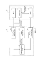
- FIG. 7 is a schematic diagram illustrating a second embodiment of a control system implementing a method for start-up lens.
- FIG. 8 shows the variation of lens lengthening speed between routes according to the second embodiment.
- FIG. 5 is a schematic diagram illustrating a first embodiment of a control system implementing a method for start-up lens.
- the system can be applied in a capturing device comprising a telescopic lens, such as a camera.
- the lens 10 comprises an optical component, and hardware structure thereof is similar to that in FIGS. 1 and 2 .
- the lens 10 is controlled by a control system 20 .
- the inner structure and connection relationships of the control system 20 are similar to those in FIG. 3 , but different in control signal, command, and angular velocity.
- the drive unit is implemented using a motor 51 in this embodiment, but is not limited thereto.
- the method for improving start-up fluency of lens comprises the following steps.
- the control system 20 drives the motor 51 to rotate at a first angular velocity ⁇ 1 , driving the lens 10 to lengthen in a first route I.
- the first route I is from the stowing position H 1 to a first switch point S 1 .
- the first switch point S 1 is between the first turning point A and the second turning point B.
- the micro-processing unit 23 receives signals from the position detection unit 21 and the reset point detection unit 22 , and determines a terminal point of the first route I accordingly. At this time, the micro-processing unit 23 outputs a first signal T 1 to the motor control unit 24 , and the motor control unit 24 outputs a first command C 1 correspondingly.
- the driving voltage for the first command C 1 may be 4.4V
- the PWM (Pulse Width Modulation) for the first command C 1 comprises at least two duty cycles such as 85% and 70%.
- the duty cycles can be switched in different time units, or a specific period such as 5 ms, such that the first angular velocity ⁇ 1 is a mix velocity driving the lens 10 to lengthen.
- the control system 20 drives the motor 51 to rotate at a second angular velocity ⁇ 2 , driving the lens 10 to lengthen in a second route II.
- the second route II is from the first switch point S 1 to a second switch point S 2 .
- the second switch point S 2 is between the first switch point S 1 and the second turning point B.
- the second angular velocity ⁇ 2 may exceed the first angular velocity ⁇ 1 .
- the micro-processing unit 23 receives signals from the position detection unit 21 , and determines a start point and a terminal point of the second route II accordingly.
- the micro-processing unit 23 outputs a second signal T 2 to the motor control unit 24 , and the motor control unit 24 outputs a second command C 2 correspondingly.
- the driving voltage for the second command C 2 may be 4.4V
- the PWM for the second command C 2 comprises at least one duty cycles such as 100%.
- the motor 51 rotates at the second angular velocity ⁇ 2 according to the driving voltage and PWM for the second command C 2 , driving the lens 10 to lengthen.
- the control system 20 drives the motor 51 to rotate at a third angular velocity ⁇ 3 , driving the lens 10 to lengthen in a third route III.
- the second route II is from the second switch point S 2 to the standby position H 2 .
- the third angular velocity ⁇ 3 may be smaller than the second angular velocity ⁇ 2 , and the first angular velocity ⁇ 1 exceeds the third angular velocity ⁇ 3 .
- the micro-processing unit 23 receives signals from the position detection unit 21 , and determines a start point and a terminal point of the third route III accordingly.
- the micro-processing unit 23 outputs a third signal T 3 to the motor control unit 24 , and the motor control unit 24 outputs a third command C 3 correspondingly.
- the driving voltage for the third command C 3 may be 3V
- the PWM for the second command C 2 comprises at least two duty cycles such as 85% and 65%.
- the duty cycles can be switched in different time unit, or a specific period such as 5 ms, such that the third angular velocity ⁇ 3 is a mix velocity driving the lens 10 to lengthen.
- the invention has following advantages.
- the micro-processing unit 23 generates various signals (T 1 , T 2 and T 3 ) for respective routes, and the motor control unit 24 outputs various commands (C 1 , C 2 and C 3 ) accordingly to the motor 51 .
- the motor 51 can rotate at various angular velocity ( ⁇ 1 , ⁇ 2 and ⁇ 3 ) corresponding to the commands (C 1 , C 2 and C 3 ), driving the lens to lengthen.
- the motor 51 can rotate at an angular velocity exceeding the first angular velocity and the third angular velocity in the second route II between the first turning point A and the second turning point B ( ⁇ 2 > ⁇ 1 and ⁇ 2 > ⁇ 3 ). In this way, the lengthening speed of the lens during the entire start-up process will be more average, improving the lengthening fluency of lens.
- the motor 51 can rotate at various angular velocities in respective routes.
- the motor 51 can rotate at an angular velocity smaller than the second angular velocity in the first and second routes comprising the first, second and third turning points (A, B and C) ( ⁇ 1 ⁇ 2 and ⁇ 3 ⁇ 2 ). In this way, noise generated during speed switch at the turning points can be reduced.
- FIG. 7 is a schematic diagram illustrating a second embodiment of a control system implementing a method for start-up lens.
- the system can be applied in a capturing device comprising a telescopic lens, such as a camera.
- the lens 10 comprises an optical component, and hardware structure thereof is similar to that in FIGS. 1 and 2 .
- the lens 10 is controlled by a control system 20 .
- the inner structure and connection relationships of the control system 20 are similar to those in FIG. 3 , but different in control signal, command, and angular velocity.
- the drive unit is implemented using a motor 51 in this embodiment, but is not limited thereto.
- the method for improving start-up fluency of lens comprises the following steps.
- the control system 20 drives the motor 51 to rotate at at least two angular velocities, driving the lens 10 to lengthen in a first route I.
- the motor 51 drives the lens 10 to lengthen based on a first preceding angular velocity ⁇ 11 and a first subsequent angular velocity ⁇ 12 .
- the first preceding angular velocity ⁇ 11 may exceed the first subsequent angular velocity ⁇ 12 .
- the first route I is from the stowing position H 1 to a first switch point S 1 .
- the first switch point S 1 is between the first turning point A and the second turning point B.
- the first route I further comprises a first preceding route I 1 and a first subsequent route I 2 (two sub-routes).
- the first preceding route I 1 is from the stowing position H 1 to a third switch point S 3 , where the third switch point S 3 is between the reset point O and the first turning point A.
- the first subsequent route I 2 is from the third switch point S 3 to the first switch point S 1 .
- the micro-processing unit 23 receives signals from the position detection unit 21 and the reset point detection unit 22 , and determines terminal points of the first preceding route I 1 and the first subsequent route I 2 accordingly.
- the micro-processing unit 23 outputs a first preceding signal T 11 and a first subsequent signal T 12 to the motor control unit 24 , and the motor control unit 24 outputs a first preceding command C 11 and a first subsequent command C 12 correspondingly.
- the driving voltage for the first preceding command C 11 and the first subsequent command C 12 may be both 4.4V
- the duty cycles of PWM for the first preceding command C 11 and the first subsequent command C 12 are 80% and 60%, respectively, driving the motor 51 to rotates at the first preceding angular velocity ⁇ 11 and the first angular subsequent velocity ⁇ 12 .
- the control system 20 drives the motor 51 to rotate at a second angular velocity ⁇ 2 , driving the lens 10 to lengthen in a second route II.
- the second route II is from the first switch point S 1 to a second switch point S 2 .
- the second switch point S 2 is between the first switch point S 1 and the second turning point B.
- the second angular velocity ⁇ 2 may exceed the first preceding velocity ⁇ 11 and the first subsequent velocity ⁇ 12 .
- the micro-processing unit 23 receives signals from the position detection unit 21 , and determines a start point and a terminal point of the second route II accordingly.
- the micro-processing unit 23 outputs a second signal T 2 to the motor control unit 24 , and the motor control unit 24 outputs a second command C 2 correspondingly.
- the driving voltage for the second command C 2 may be 4.4V
- the duty cycle of PWM for the second command C 2 may be 100%.
- the motor 51 rotates at the second angular velocity ⁇ 2 according to the driving voltage and PWM for the second command C 2 , driving the lens 10 to lengthen.
- the control system 20 drives the motor 51 to rotate at at least two angular velocities, driving the lens 10 to lengthen in a third route III.
- the motor 51 drives the lens 10 to lengthen based on a third preceding angular velocity ⁇ 31 and a third subsequent angular velocity ⁇ 32 .
- the third preceding angular velocity ⁇ 31 exceeds the third subsequent angular velocity ⁇ 32 .
- the third route III is from the second switch point S 2 to the standby position H 2 .
- the third preceding angular velocity ⁇ 31 and the third subsequent angular velocity ⁇ 32 are smaller than the second angular velocity ⁇ 2 .
- the third route III further comprises a third preceding route III 1 and a third subsequent route III 2 (two sub-routes).
- the third preceding route III 1 is from the second switch point S 2 to a fourth switch point S 4 , where the fourth switch point S 4 is between the second turning point B and the third turning point C.
- the third subsequent route III 2 is from the fourth switch point S 4 to the standby position H 2 .
- the micro-processing unit 23 receives signals from the position detection unit 21 , and determines start points and terminal points of the third preceding route III 1 and the third subsequent route III 2 accordingly.
- the micro-processing unit 23 outputs a third preceding signal T 31 and a third subsequent signal T 32 to the motor control unit 24 , and the motor control unit 24 outputs a third preceding command C 31 and a third subsequent command C 32 correspondingly.
- the driving voltage for the third preceding command C 31 and the third subsequent command C 32 may be both 3V, and the duty cycles of PWM for third preceding command C 31 and the third subsequent command C 32 are 30% and 20%, respectively, driving the motor 51 to rotate at the third preceding velocity ⁇ 31 and the third subsequent velocity ⁇ 32 .
- the second embodiment may have the same advantages in the first embodiment.
- the turning points are separated into different routes, and respective control signals and commands with various voltages and PWMs are generated for respective routes.
- the motor can rotate at different angular velocities in respective routes, improving the lengthening fluency of lens, and reducing the noise during lens lengthening.
- Methods for start-up lens may take the form of program code (i.e., executable instructions) embodied in tangible media, such as products, floppy diskettes, CD-ROMS, hard drives, or any other machine-readable storage medium, wherein, when the program code is loaded into and executed by a machine, such as a computer, the machine thereby becomes an apparatus for practicing the methods.
- the methods may also be embodied in the form of program code transmitted over some transmission medium, such as electrical wiring or cabling, through fiber optics, or via any other form of transmission, wherein, when the program code is received and loaded into and executed by a machine, such as a computer, the machine becomes an apparatus for practicing the disclosed methods.
- the program code When implemented on a general-purpose processor, the program code combines with the processor to provide a unique apparatus that operates analogously to application specific logic circuits.
Landscapes
- Physics & Mathematics (AREA)
- General Physics & Mathematics (AREA)
- Lens Barrels (AREA)
- Studio Devices (AREA)
Abstract
Description
Claims (20)
Applications Claiming Priority (3)
| Application Number | Priority Date | Filing Date | Title |
|---|---|---|---|
| TW095116393A TW200742924A (en) | 2006-05-09 | 2006-05-09 | Method for improving smoothness of lens operation during start-up |
| TW95116393 | 2006-05-09 | ||
| TW95116393A | 2006-05-09 |
Publications (2)
| Publication Number | Publication Date |
|---|---|
| US20070263502A1 US20070263502A1 (en) | 2007-11-15 |
| US7785022B2 true US7785022B2 (en) | 2010-08-31 |
Family
ID=38684974
Family Applications (1)
| Application Number | Title | Priority Date | Filing Date |
|---|---|---|---|
| US11/745,497 Expired - Fee Related US7785022B2 (en) | 2006-05-09 | 2007-05-08 | Methods for start-up lens |
Country Status (2)
| Country | Link |
|---|---|
| US (1) | US7785022B2 (en) |
| TW (1) | TW200742924A (en) |
Families Citing this family (1)
| Publication number | Priority date | Publication date | Assignee | Title |
|---|---|---|---|---|
| TWI400478B (en) | 2009-02-23 | 2013-07-01 | Asia Optical Co Inc | Can increase the positioning accuracy of the zoom lens |
Citations (4)
| Publication number | Priority date | Publication date | Assignee | Title |
|---|---|---|---|---|
| US6381076B1 (en) * | 2000-09-26 | 2002-04-30 | Canon Kabushiki Kaisha | Zoom lens barrel |
| US20020141744A1 (en) * | 2001-02-06 | 2002-10-03 | Shinichi Masuda | Variable power lens barrel and camera |
| US6480677B1 (en) * | 1999-01-20 | 2002-11-12 | Minolta Co., Ltd. | Zooming and focusing mechanism of camera |
| US6839086B1 (en) * | 1998-06-11 | 2005-01-04 | Konica Corporation | Camera including multiple lenses, a ranging means, and multiple image processors |
-
2006
- 2006-05-09 TW TW095116393A patent/TW200742924A/en not_active IP Right Cessation
-
2007
- 2007-05-08 US US11/745,497 patent/US7785022B2/en not_active Expired - Fee Related
Patent Citations (4)
| Publication number | Priority date | Publication date | Assignee | Title |
|---|---|---|---|---|
| US6839086B1 (en) * | 1998-06-11 | 2005-01-04 | Konica Corporation | Camera including multiple lenses, a ranging means, and multiple image processors |
| US6480677B1 (en) * | 1999-01-20 | 2002-11-12 | Minolta Co., Ltd. | Zooming and focusing mechanism of camera |
| US6381076B1 (en) * | 2000-09-26 | 2002-04-30 | Canon Kabushiki Kaisha | Zoom lens barrel |
| US20020141744A1 (en) * | 2001-02-06 | 2002-10-03 | Shinichi Masuda | Variable power lens barrel and camera |
Also Published As
| Publication number | Publication date |
|---|---|
| TW200742924A (en) | 2007-11-16 |
| TWI305603B (en) | 2009-01-21 |
| US20070263502A1 (en) | 2007-11-15 |
Similar Documents
| Publication | Publication Date | Title |
|---|---|---|
| US7675548B2 (en) | Shake correcting device, shake correcting method and control program for implementing the method | |
| KR20120020937A (en) | Electric power steering apparatus | |
| US7785022B2 (en) | Methods for start-up lens | |
| JP4803892B2 (en) | Surveying instrument | |
| US20110095712A1 (en) | Ultrasonic motor device | |
| JPH0431808A (en) | Zoom lens controller | |
| JP2005333377A (en) | Image reading device | |
| JP2005117774A (en) | Driving unit for dc motor | |
| JP4998175B2 (en) | Vehicle headlamp device | |
| US7990464B2 (en) | Focusing device with uninterrupted excitation | |
| JP3621585B2 (en) | Information detection device | |
| JP2008029177A (en) | Semiconductor device | |
| JP2009149209A (en) | Wiper device and wiper motor driving method | |
| KR200167708Y1 (en) | Motor Drive with Interface Circuit | |
| JP2005278046A (en) | Fader device | |
| JP2005324660A (en) | Wiper control device | |
| US20110243549A1 (en) | Driving force transmitting device and camera platform device using the same | |
| JP2004363669A (en) | Optical communication apparatus | |
| JP4300613B2 (en) | Motor drive control device and motor drive control method | |
| JP4200773B2 (en) | Vehicle headlamp control device | |
| JP2007247286A (en) | Opening/closing body driving control device | |
| JP2008079395A (en) | Drive control device for vibration actuator, lens barrel and camera | |
| JP2001311975A (en) | Image blurring preventing device | |
| JPS62281797A (en) | Drive control of stepping motor | |
| JPH02130079A (en) | Autofocus video camera |
Legal Events
| Date | Code | Title | Description |
|---|---|---|---|
| AS | Assignment |
Owner name: ASIA OPTICAL CO., INC., TAIWAN Free format text: ASSIGNMENT OF ASSIGNORS INTEREST;ASSIGNORS:JINN, YU-SHUH;YANG, MING-CHYI;LIN, HSIN-HO;REEL/FRAME:019259/0710 Effective date: 20070503 |
|
| AS | Assignment |
Owner name: ASIA OPTICAL INTERNATIONAL LTD., VIRGIN ISLANDS, B Free format text: ASSIGNMENT OF ASSIGNORS INTEREST;ASSIGNOR:ASIA OPTICAL CO., INC.;REEL/FRAME:028843/0190 Effective date: 20120816 |
|
| FPAY | Fee payment |
Year of fee payment: 4 |
|
| FEPP | Fee payment procedure |
Free format text: MAINTENANCE FEE REMINDER MAILED (ORIGINAL EVENT CODE: REM.) |
|
| LAPS | Lapse for failure to pay maintenance fees |
Free format text: PATENT EXPIRED FOR FAILURE TO PAY MAINTENANCE FEES (ORIGINAL EVENT CODE: EXP.); ENTITY STATUS OF PATENT OWNER: LARGE ENTITY |
|
| STCH | Information on status: patent discontinuation |
Free format text: PATENT EXPIRED DUE TO NONPAYMENT OF MAINTENANCE FEES UNDER 37 CFR 1.362 |
|
| FP | Lapsed due to failure to pay maintenance fee |
Effective date: 20180831 |