US7784402B2 - Method for loading printing plate on imaging device - Google Patents
Method for loading printing plate on imaging device Download PDFInfo
- Publication number
- US7784402B2 US7784402B2 US11/739,152 US73915207A US7784402B2 US 7784402 B2 US7784402 B2 US 7784402B2 US 73915207 A US73915207 A US 73915207A US 7784402 B2 US7784402 B2 US 7784402B2
- Authority
- US
- United States
- Prior art keywords
- printing plate
- leading edge
- plate
- clamp
- drum
- Prior art date
- Legal status (The legal status is an assumption and is not a legal conclusion. Google has not performed a legal analysis and makes no representation as to the accuracy of the status listed.)
- Active, expires
Links
Images


Classifications
-
- B—PERFORMING OPERATIONS; TRANSPORTING
- B65—CONVEYING; PACKING; STORING; HANDLING THIN OR FILAMENTARY MATERIAL
- B65H—HANDLING THIN OR FILAMENTARY MATERIAL, e.g. SHEETS, WEBS, CABLES
- B65H5/00—Feeding articles separated from piles; Feeding articles to machines
- B65H5/08—Feeding articles separated from piles; Feeding articles to machines by grippers, e.g. suction grippers
- B65H5/12—Revolving grippers, e.g. mounted on arms, frames or cylinders
-
- B—PERFORMING OPERATIONS; TRANSPORTING
- B65—CONVEYING; PACKING; STORING; HANDLING THIN OR FILAMENTARY MATERIAL
- B65H—HANDLING THIN OR FILAMENTARY MATERIAL, e.g. SHEETS, WEBS, CABLES
- B65H9/00—Registering, e.g. orientating, articles; Devices therefor
- B65H9/12—Registering, e.g. orientating, articles; Devices therefor carried by article grippers
-
- B—PERFORMING OPERATIONS; TRANSPORTING
- B41—PRINTING; LINING MACHINES; TYPEWRITERS; STAMPS
- B41C—PROCESSES FOR THE MANUFACTURE OR REPRODUCTION OF PRINTING SURFACES
- B41C1/00—Forme preparation
- B41C1/10—Forme preparation for lithographic printing; Master sheets for transferring a lithographic image to the forme
- B41C1/1075—Mechanical aspects of on-press plate preparation
-
- B—PERFORMING OPERATIONS; TRANSPORTING
- B65—CONVEYING; PACKING; STORING; HANDLING THIN OR FILAMENTARY MATERIAL
- B65H—HANDLING THIN OR FILAMENTARY MATERIAL, e.g. SHEETS, WEBS, CABLES
- B65H2301/00—Handling processes for sheets or webs
- B65H2301/30—Orientation, displacement, position of the handled material
- B65H2301/36—Positioning; Changing position
-
- B—PERFORMING OPERATIONS; TRANSPORTING
- B65—CONVEYING; PACKING; STORING; HANDLING THIN OR FILAMENTARY MATERIAL
- B65H—HANDLING THIN OR FILAMENTARY MATERIAL, e.g. SHEETS, WEBS, CABLES
- B65H2701/00—Handled material; Storage means
- B65H2701/10—Handled articles or webs
- B65H2701/13—Parts concerned of the handled material
- B65H2701/131—Edges
- B65H2701/1311—Edges leading edge
-
- B—PERFORMING OPERATIONS; TRANSPORTING
- B65—CONVEYING; PACKING; STORING; HANDLING THIN OR FILAMENTARY MATERIAL
- B65H—HANDLING THIN OR FILAMENTARY MATERIAL, e.g. SHEETS, WEBS, CABLES
- B65H2701/00—Handled material; Storage means
- B65H2701/10—Handled articles or webs
- B65H2701/19—Specific article or web
- B65H2701/1928—Printing plate
-
- Y—GENERAL TAGGING OF NEW TECHNOLOGICAL DEVELOPMENTS; GENERAL TAGGING OF CROSS-SECTIONAL TECHNOLOGIES SPANNING OVER SEVERAL SECTIONS OF THE IPC; TECHNICAL SUBJECTS COVERED BY FORMER USPC CROSS-REFERENCE ART COLLECTIONS [XRACs] AND DIGESTS
- Y10—TECHNICAL SUBJECTS COVERED BY FORMER USPC
- Y10S—TECHNICAL SUBJECTS COVERED BY FORMER USPC CROSS-REFERENCE ART COLLECTIONS [XRACs] AND DIGESTS
- Y10S101/00—Printing
- Y10S101/36—Means for registering or alignment of print plates on print press structure
Definitions
- the invention relates to printing and, in particular to providing registered images on printing plates.
- Printing plates may be imaged on a plate-making machine and then transferred to a printing press. Once on the printing press, the images from the printing plates are transferred to paper or other suitable substrates. It is important that images printed using a printing press be properly aligned with the substrate on which they are printed. Obtaining such alignment typically involves:
- One common technique of aligning the printing plate on the drum of a printing press involves using the reference edge and the orthogonal edge reference point to align the printing plate on a punching machine and punching registration holes in the printing plate.
- the printing plate may then be aligned on the drum of the printing press with registration pins that project through the registration holes.
- EP 1 081 458 A2 describes an apparatus for detecting a plate edge using a light beam and detector.
- U.S. Pat. No. 6,815,702 (Kiermeier et al.) a method and apparatus are disclosed to locate an edge of an imageable plate mounted on a drum or other support surface.
- a light source and light sensor are used to measure the difference in reflectivity between the plate and the support surface.
- the drum or support surface contains at least one groove to increase the difference in reflectivity between the plate and the support surface.
- the groove may also contain an anti-reflecting layer to further increase the difference in reflectivity.
- the groove may also have a geometric shape that causes incident light to be directed away from the light sensor.
- a further important aspect of the entire plate alignment process is the method of loading of the plate onto the imaging drum. While there is some description in the prior art of systems for correcting the placement of a plate on a drum, it is generally more effective to get the plate loaded as close to perfectly aligned as possible during the initial loading step. In the case of the method described in U.S. patent application Ser. No. 11/693,007, the fully loaded printing plate needs to be protruding over the slot and aligned as closely as possible with the edge of the slot.
- U.S. Pat. No. 6,604,465 (Tice et al.) describes the loading of a printing plate onto an external drum while rotating the drum in a first direction. No mention is made of rotating the drum in another direction while loading the plate. While the patent does disclose a method for aligning of the printing plate without requiring any holes to be punched in the printing plate, alignment of the printing plate is in fact done using pins on the drum. The printing plate is then imaged while the drum is rotated in the first, or in a second, opposite direction. Finally, the printing plate is unloaded from the drum while rotating the drum in the second direction.
- U.S. Pat. Nos. 6,260,482 and 6,189,452 respectively describe a method and apparatus for loading and unloading plates to external drum devices based on movable clamps.
- the system is characterized by clamps, ideally in pairs of which the members are circumferentially disposed with respect to each other, that are movable over the surface, preferably along circumferential tracks, enabling the attachment of multiple plates, end-to-end and/or side-by-side.
- a first clamp of each relevant pair is first opened and then engaged to the leading edge of the printing plate, which is fed from a suitably positioned loading mechanism, and then releasing the clamps to grip the leading edge of the printing plate.
- the drum is then rotated in a first direction to pull the plate and wrap it around the drum.
- the other clamp of each pair is opened and the drum is rotated in a second opposite direction, while the clamp remains stationary, until the trailing edge of the plate is engaged by the clamp, whereupon the clamp is released, thus gripping the trailing edge by slidable clamps.
- the plate is demounted in the same general order, by first releasing the first clamp of each pair (which grips the leading edge of the plate) and moving it away from the plate in the second direction of the drum, thus freeing that edge, then rotating the drum in the first direction, thus pushing the plate onto a suitably position unloading bin, and finally releasing the second clamp of the pair, thus freeing the plate. No mention is made of moving the drum in different directions in order to correctly position the plate on the drum.
- U.S. Pat. No. 5,992,325 (Schumann et al.) describes a method for automatically detecting the trailing edge of a printing plate.
- the detecting can be the determination within a trailing edge clamp of either the location of the edge, or the determination of the presence of the trailing edge.
- a sensor is employed.
- This patent also discloses a method for loading the printing plate. The method starts, after release of the trailing edge of a previous plate, with the ejection of the previous printing plate, which is achieved by rotating the drum in a first direction to push the plate by its leading edge. The leading edge of that plate is then unclamped. The drum is then rotated in a second, opposite direction by a very small amount, enough to clear the leading edge of the previous plate.
- the drum is then rotated in the first direction again to receive the leading edge of a new plate into the same clamp from which the leading edge of the earlier plate has been ejected. The presence and or location of this leading edge is determined by the sensor.
- the printing plate is then clamped by its leading edge.
- the next step comprises rotating the drum in the second direction in order to wrap the printing plate on the drum. Suitable steps are taken to tauten the printing plate on the drum and to secure the trailing edge. While the patent describes small rotations of the drum to load and release the printing plate, it does not address the matter of alignment of the printing plate or its exact positioning relative to any possible slot in the drum.
- an edge detection system is described, based on using a digital camera to image the edges of a printing plate perpendicular to the sub-scan direction. Based on the information so obtained, the image data is then adjusted to compensate for any misalignment between the plate and the drum on which it is loaded.
- an edge detection system is described, based on using a digital camera to image the leading edge of a printing plate.
- the system employs a slot in the cylindrical surface of an imaging drum, the slot having a radially recessed surface that has diffusely reflective surfaces and substantially non-reflective surfaces. The system allows the leading edge of a printing plate protruding over the slot to be located through the leading edge clamps by illumination with a suitable illumination source and imaging with a digital camera.
- the present invention constitutes a method for aligning a leading edge of one or more printing plates to a cylindrical axis of an imaging drum, the imaging drum comprising at least one leading edge printing plate clamp having a clamp surface disposed parallel to the cylindrical axis.
- the method comprises resting the leading edge on a cylindrical surface of the imaging drum and rotating the imaging drum in a reverse direction about a cylindrical axis to contact with the clamp surface a point along the leading edge and rotate the at least one printing plate until the leading edge is in alignment with the clamp surface.
- the invention constitutes a method for aligning a leading edge of one or more printing plates to an axially disposed slot in a cylindrical surface of an imaging drum, the imaging drum comprising at least one leading edge printing plate clamp having a clamp surface disposed parallel to the slot.
- the method comprises straightening the leading edge against the clamp surface by rotating the imaging drum in a reverse direction about its cylindrical axis and then rotating the imaging drum about its cylindrical axis in a forward direction until the leading edge protrudes over the slot by a predetermined amount.
- the straightening comprises resting the leading edge of the printing plate on the cylindrical surface of the imaging drum and rotating the imaging drum in a reverse direction about its cylindrical axis to contact with the clamp surface a point along the leading edge of the at least one printing plate and to rotate the printing plate until its leading edge is in alignment with the clamp surface.
- the invention constitutes a method for determining an alignment of at least one printing plate relative to an imaging drum on which the at least one plate is mounted, the method comprising aligning to an axially disposed slot in a cylindrical surface of the imaging drum a leading edge of the at least one printing plate, determining a location of at least one point on the leading edge of the at least one printing plate; and determining the alignment of the printing plate at least in part from the location of at least a part of the leading edge in a digital camera image of the at least one point, and from a position of the digital camera, used for obtaining the digital image, relative to the imaging drum during the capturing of the at least one digital camera image of the at least one point.
- FIG. 1 is a schematic diagram of an external drum-type plate-making machine
- FIG. 2 is a cross-section of the plate-making machine of FIG. 1 showing a printing plate positioned on a loading table;
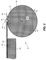
- FIG. 3 is a cross-section of the plate-making machine of FIG. 1 , showing a printing plate rested on the cylindrical surface of the drum of the plate-making machine;
- FIG. 4 is a cross-section of the plate-making machine of FIG. 1 , showing a printing plate being straightened by rotation of the imaging drum of the plate-making machine in the reverse direction;
- FIG. 5 is a cross-section of the plate-making machine of FIG. 1 , showing a printing plate being positioned so that its leading edge protrudes over a slot in the cylindrical surface of the imaging drum of the plate-making machine;
- FIG. 6 is a cross-section of the plate-making machine of FIG. 1 , showing a leading edge of a printing plate being clamped in position to the cylindrical surface of the imaging drum of the plate-making machine of FIG. 1 by a leading edge printing plate clamp;
- FIG. 7 is a cross-section of the plate-making machine of FIG. 1 , showing a printing plate being wrapped onto the cylindrical surface of the imaging drum of the plate-making machine;
- FIG. 8 is a cross-section of the plate-making machine of FIG. 1 , showing a printing plate fully wrapped onto the cylindrical surface of the imaging drum of the plate-making machine;
- FIG. 9 is a cross-section of the plate-making machine of FIG. 1 , showing a printing plate being clamped in position to the cylindrical surface of the imaging drum of the plate-making machine of FIG. 1 by a trailing edge printing plate clamp;
- FIG. 10 is a flow diagram of a first embodiment of the present invention as shown in FIGS. 1-4 and 6 - 9 ;
- FIG. 11 is a flow diagram of a second embodiment of the present invention as shown in FIGS. 1-9 .
- FIG. 1 is a schematic depiction of a plate-making machine 10 of the present invention comprising an imaging drum 20 having cylindrical surface 30 .
- Imaging drum 20 is rotatable both in forward direction 40 and in reverse direction 50 , about cylindrical axis 60 .
- Imaging drum 20 comprises a slot 70 extending in an axial direction along cylindrical surface 30 of imaging drum 20 .
- the slot can be of the type described in commonly assigned and co-pending U.S. patent application Ser. No. 11/693,007.
- Imaging drum 20 comprises trailing edge printing plate clamp 80 for clamping a trailing edge of a printing plate to cylindrical surface 30 .
- Trailing edge printing plate clamp 80 may comprise a plurality of individual printing plate clamps arranged in line with one another on cylindrical surface 30 in an axial direction with respect to imaging cylinder 20 .
- Imaging drum 20 further comprises leading edge printing plate clamp 90 for clamping a leading edge of a printing plate to cylindrical surface 30 .
- Leading edge printing plate clamp 80 may comprise a plurality of individual printing plate clamps arranged in line with one another on cylindrical surface 30 in an axial direction with respect to imaging cylinder 20 .
- Leading edge printing plate clamp 90 comprises a clamp surface 100 .
- Clamp surface 100 may be any surface or part of leading edge printing plate clamp, including a one-dimensional line on leading edge printing plate clamp 90 , as long as the requirement is met of clamp surface 100 lying in a plane intersecting cylindrical surface 30 along a line that is parallel to cylindrical axis 60 .
- Loading table 130 has loading surface 120 on which may be placed a printing plate 110 for loading onto imaging drum 20 .
- Loading table 130 is disposed proximate cylindrical surface 30 , and is arranged to allow a leading edge of plate 110 to rest on cylindrical surface 30 of imaging drum 20 while the bulk of printing plate 110 remains on loading surface 120 of loading table 130 .
- the imaging subsystem, drive systems and controllers of plate-making machine 10 are not shown in FIG. 1 , as the invention pertains to the loading of printing plates.
- FIG. 1 and FIGS. 2 to 9 show the steps of loading a printing plate onto the imaging drum of a plate-making machine.
- un-imaged printing plate 110 is shown positioned on loading surface 120 of loading table 130 before the method of the present invention is initiated.
- printing plate 110 may be located elsewhere.
- printing plate 110 is placed with its leading edge (a) resting on cylindrical surface 30 and (b) substantially parallel to slot 70 .
- the placement of printing plate 110 will typically not be such that the leading edge of printing plate 110 is perfectly parallel to slot 70 .
- the bulk of printing plate 110 remains on loading surface 120 of loading table 130 . This allows imaging drum 20 to rotate and thereby slide its cylindrical surface 30 under the leading edge of printing plate 110 . The friction so created between cylindrical surface 30 and printing plate 110 is not enough to reposition printing plate 110 .
- imaging drum 20 is rotated slowly in direction 50 , also referred to herein as the “reverse direction.”
- clamp surface 100 engages with at least one point along the leading edge of printing plate 110 and, to the degree that the leading edge of printing plate 110 is not parallel to clamp surface 100 , printing plate 110 is rotated by the advancing clamp surface 100 until the leading edge of printing plate 110 is aligned to clamp surface 100 and thereby to slot 70 . Since the placement of printing plate 110 in FIG. 1 is already roughly aligned to slot 70 , not much rotation is required to align printing plate 110 once the first point along its leading edge has made contact with clamp surface 100 .
- the leading edge of printing plate 110 is substantially aligned with axis 60 of imaging drum 20 .
- the term “straightening” of the printing plate is used to describe the rotation and alignment that printing plate 110 undergoes when subjected to this step of the invention. To the degree that any misalignment still remains, it may be addressed by the image rotation method described in commonly-assigned and co-pending U.S. patent application Ser. No. 11/693,007.
- the next step comprises closing.
- imaging drum 20 is rotated a predetermined distance in direction 40 , also referred to herein as the “forward direction,” thereby to cause cylindrical surface to slide under printing plate 110 until the leading edge of printing plate 110 protrudes a predetermined distance over the edge of slot 70 nearest to loading table 130 .
- the leading edge of printing plate 110 is positioned in this way to protrude a distance greater than zero but less than the width of slot 70 over the edge of slot 70 nearest loading table 130 .
- the leading edge of printing plate 110 is positioned to protrude a distance greater than zero but less than half the width of slot 70 over the edge of slot 70 nearest loading table 130 .
- the next step 230 holds for all embodiments and is that of closing leading edge printing plate clamp 90 so as to hold the leading edge of printing plate 110 to cylindrical surface 30 . This is shown in FIG. 6 .
- the next step 240 in both embodiments of the present invention comprises rotating imaging drum 20 in the forward direction in order to wrap printing plate 110 onto cylindrical surface 30 .
- FIG. 7 shows this process some distance through the step.
- trailing edge printing plate clamp is closed, as shown in FIG. 9 , to hold printing plate 110 to cylindrical surface 30 .
- Printing plate 110 can also, either as alternative to trailing edge clamp 80 or in addition to trailing edge clamp 80 , be held to cylindrical surface 30 by means of a vacuum that is applied through orifices in imaging drum 110 . Techniques of applying a vacuum to an imaging drum of a plate-making machine are well-known in the art and will not be discussed here.
- the image rotation method of commonly-assigned and copending U.S. patent application Ser. No. 11/693,007 can be used to detect and locate the leading edge of printing plate 110 .
- a location of at least one point on the leading edge of printing plate 110 is then determined.
- the resulting alignment of printing plate 110 can then be determined, at least in part, from the location of the at least one point in at least one digital image of the leading edge, taken with a digital camera, together with the known position of the digital camera relative to the imaging drum during the capturing of the digital camera image of the at least one point.
- two points along the leading edge of printing plate 110 are determined in this fashion, and used to determine the alignment by the method of commonly-assigned and copending U.S. patent application Ser. No. 11/693,007.
- the image may be rotated to compensate for such remaining misalignment, using the image rotation method described in commonly-assigned and copending U.S. patent application Ser. No. 11/693,007.
- the printing plate is then imaged.
- the method of the present invention is simple, trouble free, and inexpensive, as it uses components that are necessarily already incorporated in typical imaging drums, like leading edge clamps and trailing edge clamps. It also avoids the loading problems typical of many prior art plate-making machines, in which plates need to rotate and register against pins in the drum. Such prior art systems and techniques require high loading force which can cause the plates to buckle and give imaging errors. This is particularly true of so-called very large format (VLF) printing plates, which are heavy and cumbersome. Given their large size, damage to such plates is often an expensive proposition and is best avoided.
- VLF very large format
Landscapes
- Engineering & Computer Science (AREA)
- Mechanical Engineering (AREA)
- Exposure And Positioning Against Photoresist Photosensitive Materials (AREA)
- Manufacture Or Reproduction Of Printing Formes (AREA)
Abstract
Description
-
- carefully aligning a reference edge of a printing plate with pins or other features on the plate making machine;
- detecting one reference point on an orthogonal edge of the printing plate (i.e. orthogonal to the reference edge) at a known distance from the reference pins;
- imaging the printing plate; and
- using the reference edge and the orthogonal edge reference point to align the printing plate on a drum of the printing press.
- 10 plate-making machine (platesetter)
- 20 imaging drum
- 30 cylindrical surface
- 40 forward direction of rotation
- 50 reverse direction of rotation
- 60 cylindrical axis
- 70 slot
- 80 trailing edge printing plate clamp
- 90 leading edge printing plate clamp
- 100 clamp surface
- 110 printing plate
- 120 loading surface
- 130 loading table
- 200 printing plate placed with its leading edge resting on cylindrical surface of drum
- 210 straightening of the printing plate by rotating imaging drum in reverse direction
- 220 printing plate positioned with leading edge protruding over slot by rotating imaging drum forward
- 230 leading edge of printing plate clamped by leading edge printing plate clamp
- 240 printing plate wrapped onto imaging drum by rotating imaging drum forward
- 250 printing plate clamped by trailing edge clamp
Claims (7)
Priority Applications (1)
| Application Number | Priority Date | Filing Date | Title |
|---|---|---|---|
| US11/739,152 US7784402B2 (en) | 2007-04-24 | 2007-04-24 | Method for loading printing plate on imaging device |
Applications Claiming Priority (1)
| Application Number | Priority Date | Filing Date | Title |
|---|---|---|---|
| US11/739,152 US7784402B2 (en) | 2007-04-24 | 2007-04-24 | Method for loading printing plate on imaging device |
Publications (2)
| Publication Number | Publication Date |
|---|---|
| US20080264287A1 US20080264287A1 (en) | 2008-10-30 |
| US7784402B2 true US7784402B2 (en) | 2010-08-31 |
Family
ID=39885469
Family Applications (1)
| Application Number | Title | Priority Date | Filing Date |
|---|---|---|---|
| US11/739,152 Active 2029-01-23 US7784402B2 (en) | 2007-04-24 | 2007-04-24 | Method for loading printing plate on imaging device |
Country Status (1)
| Country | Link |
|---|---|
| US (1) | US7784402B2 (en) |
Citations (12)
| Publication number | Priority date | Publication date | Assignee | Title |
|---|---|---|---|---|
| US4876456A (en) | 1986-12-19 | 1989-10-24 | Dainippon Screen Mfg. Co., Ltd. | Method of and apparatus for detecting presence or absence of photosensitive object at a prescribed position |
| US4881086A (en) | 1987-08-31 | 1989-11-14 | Minolta Camera Kabushiki Kaisha | Laser recorder with sheet edge detection |
| US5992325A (en) | 1998-01-30 | 1999-11-30 | Heidelberger Druckmaschinen Aktiengesellschaft | Method and device for automatically detecting at least one printing plate edge |
| US6189452B1 (en) | 1998-04-30 | 2001-02-20 | Creoscitex Corporation Ltd. | Apparatus for loading and unloading plates to external drum devices having movable clamps |
| EP1081458A2 (en) | 1999-08-31 | 2001-03-07 | CreoScitex Corporation Ltd. | Apparatus and method for edge detection |
| US6318262B1 (en) | 2000-02-25 | 2001-11-20 | Agfa Corporation | External drum imaging system |
| US6604465B2 (en) | 2000-02-25 | 2003-08-12 | Agfa Corporation | Pin registration system for mounting different width printing plates |
| US6722280B2 (en) * | 2002-08-09 | 2004-04-20 | Agfa Corporation | Method and system for simultaneous loading and unloading of substrates in platestter |
| US6736396B2 (en) * | 2000-07-28 | 2004-05-18 | Fuji Photo Film Co., Ltd. | Sheet member holding device |
| US6742455B2 (en) * | 2001-08-23 | 2004-06-01 | Fuji Photo Film Co., Ltd. | Method for holding sheet material, and image recording apparatus |
| US6815702B2 (en) | 2001-10-23 | 2004-11-09 | Agfa Corporation | Method and apparatus for detection of an edge of a printing plate mounted on a drum imaging system |
| US7124686B2 (en) * | 2004-04-28 | 2006-10-24 | Heidelberger Druckmaschinen Ag | Apparatus for clamping and holding a printing plate on an exposure drum |
-
2007
- 2007-04-24 US US11/739,152 patent/US7784402B2/en active Active
Patent Citations (13)
| Publication number | Priority date | Publication date | Assignee | Title |
|---|---|---|---|---|
| US4876456A (en) | 1986-12-19 | 1989-10-24 | Dainippon Screen Mfg. Co., Ltd. | Method of and apparatus for detecting presence or absence of photosensitive object at a prescribed position |
| US4881086A (en) | 1987-08-31 | 1989-11-14 | Minolta Camera Kabushiki Kaisha | Laser recorder with sheet edge detection |
| US6260482B1 (en) | 1997-05-30 | 2001-07-17 | Creoscitex Corporation Ltd | Method for loading and unloading plates to external drum devices based on movable clamps |
| US5992325A (en) | 1998-01-30 | 1999-11-30 | Heidelberger Druckmaschinen Aktiengesellschaft | Method and device for automatically detecting at least one printing plate edge |
| US6189452B1 (en) | 1998-04-30 | 2001-02-20 | Creoscitex Corporation Ltd. | Apparatus for loading and unloading plates to external drum devices having movable clamps |
| EP1081458A2 (en) | 1999-08-31 | 2001-03-07 | CreoScitex Corporation Ltd. | Apparatus and method for edge detection |
| US6318262B1 (en) | 2000-02-25 | 2001-11-20 | Agfa Corporation | External drum imaging system |
| US6604465B2 (en) | 2000-02-25 | 2003-08-12 | Agfa Corporation | Pin registration system for mounting different width printing plates |
| US6736396B2 (en) * | 2000-07-28 | 2004-05-18 | Fuji Photo Film Co., Ltd. | Sheet member holding device |
| US6742455B2 (en) * | 2001-08-23 | 2004-06-01 | Fuji Photo Film Co., Ltd. | Method for holding sheet material, and image recording apparatus |
| US6815702B2 (en) | 2001-10-23 | 2004-11-09 | Agfa Corporation | Method and apparatus for detection of an edge of a printing plate mounted on a drum imaging system |
| US6722280B2 (en) * | 2002-08-09 | 2004-04-20 | Agfa Corporation | Method and system for simultaneous loading and unloading of substrates in platestter |
| US7124686B2 (en) * | 2004-04-28 | 2006-10-24 | Heidelberger Druckmaschinen Ag | Apparatus for clamping and holding a printing plate on an exposure drum |
Also Published As
| Publication number | Publication date |
|---|---|
| US20080264287A1 (en) | 2008-10-30 |
Similar Documents
| Publication | Publication Date | Title |
|---|---|---|
| US6604465B2 (en) | Pin registration system for mounting different width printing plates | |
| JP3833922B2 (en) | Sheet material positioning device | |
| US6295929B1 (en) | External drum imaging system | |
| US6412413B1 (en) | Media clamp for external drum imaging system | |
| US6318262B1 (en) | External drum imaging system | |
| US7784402B2 (en) | Method for loading printing plate on imaging device | |
| US6729234B2 (en) | Actuation system in an imaging system | |
| US20030056671A1 (en) | Sheet member positioning device and image recording device | |
| US6968782B2 (en) | Printing plate registration and imaging | |
| US6755132B1 (en) | Registration pin system | |
| US7362347B2 (en) | Image recording apparatus having a recording drum rotatable with a recording medium mounted peripherally thereof | |
| US6865987B2 (en) | Sheet-shaped material positioning device and printing plate precursor exposure device | |
| JP2004096748A (en) | Media clamping apparatus and method for external drum imaging system | |
| CN107428153B (en) | Mounting apparatus and method for mounting a printed board on a print carrier | |
| US6772688B2 (en) | Imaging system with automated plate locating mechanism and method for loading printing plate | |
| US20110192304A1 (en) | Printing plate registration | |
| US6772691B2 (en) | System and method for registering media in an imaging system | |
| JP3954516B2 (en) | Plate positioning and processing method and plate positioning and processing apparatus | |
| US20060038874A1 (en) | Image recorder | |
| EP1388416B1 (en) | Method and system for simultaneous loading and unloading of substrates in platesetter | |
| US6880462B2 (en) | Apparatus and method for peeling a printing plate from a stack of plates | |
| CN112666802B (en) | Plate specification detection method and device | |
| JP2003095489A (en) | Sheet material positioning device and image recording device | |
| EP1698462B1 (en) | System and method to prevent movement of a prinitng plate during clamping | |
| JP2007505765A (en) | How to change the plate mounting conditions in the plate cylinder |
Legal Events
| Date | Code | Title | Description |
|---|---|---|---|
| AS | Assignment |
Owner name: EASTMAN KODAK COMPANY, NEW YORK Free format text: ASSIGNMENT OF ASSIGNORS INTEREST;ASSIGNORS:CUMMINGS, CALVIN D.;HAWES, PETER;REEL/FRAME:019199/0698 Effective date: 20070417 |
|
| FEPP | Fee payment procedure |
Free format text: PAYOR NUMBER ASSIGNED (ORIGINAL EVENT CODE: ASPN); ENTITY STATUS OF PATENT OWNER: LARGE ENTITY |
|
| STCF | Information on status: patent grant |
Free format text: PATENTED CASE |
|
| AS | Assignment |
Owner name: CITICORP NORTH AMERICA, INC., AS AGENT, NEW YORK Free format text: SECURITY INTEREST;ASSIGNORS:EASTMAN KODAK COMPANY;PAKON, INC.;REEL/FRAME:028201/0420 Effective date: 20120215 |
|
| AS | Assignment |
Owner name: WILMINGTON TRUST, NATIONAL ASSOCIATION, AS AGENT, Free format text: PATENT SECURITY AGREEMENT;ASSIGNORS:EASTMAN KODAK COMPANY;PAKON, INC.;REEL/FRAME:030122/0235 Effective date: 20130322 Owner name: WILMINGTON TRUST, NATIONAL ASSOCIATION, AS AGENT, MINNESOTA Free format text: PATENT SECURITY AGREEMENT;ASSIGNORS:EASTMAN KODAK COMPANY;PAKON, INC.;REEL/FRAME:030122/0235 Effective date: 20130322 |
|
| AS | Assignment |
Owner name: JPMORGAN CHASE BANK, N.A., AS ADMINISTRATIVE, DELAWARE Free format text: INTELLECTUAL PROPERTY SECURITY AGREEMENT (FIRST LIEN);ASSIGNORS:EASTMAN KODAK COMPANY;FAR EAST DEVELOPMENT LTD.;FPC INC.;AND OTHERS;REEL/FRAME:031158/0001 Effective date: 20130903 Owner name: BARCLAYS BANK PLC, AS ADMINISTRATIVE AGENT, NEW YORK Free format text: INTELLECTUAL PROPERTY SECURITY AGREEMENT (SECOND LIEN);ASSIGNORS:EASTMAN KODAK COMPANY;FAR EAST DEVELOPMENT LTD.;FPC INC.;AND OTHERS;REEL/FRAME:031159/0001 Effective date: 20130903 Owner name: PAKON, INC., NEW YORK Free format text: RELEASE OF SECURITY INTEREST IN PATENTS;ASSIGNORS:CITICORP NORTH AMERICA, INC., AS SENIOR DIP AGENT;WILMINGTON TRUST, NATIONAL ASSOCIATION, AS JUNIOR DIP AGENT;REEL/FRAME:031157/0451 Effective date: 20130903 Owner name: EASTMAN KODAK COMPANY, NEW YORK Free format text: RELEASE OF SECURITY INTEREST IN PATENTS;ASSIGNORS:CITICORP NORTH AMERICA, INC., AS SENIOR DIP AGENT;WILMINGTON TRUST, NATIONAL ASSOCIATION, AS JUNIOR DIP AGENT;REEL/FRAME:031157/0451 Effective date: 20130903 Owner name: BARCLAYS BANK PLC, AS ADMINISTRATIVE AGENT, NEW YO Free format text: INTELLECTUAL PROPERTY SECURITY AGREEMENT (SECOND LIEN);ASSIGNORS:EASTMAN KODAK COMPANY;FAR EAST DEVELOPMENT LTD.;FPC INC.;AND OTHERS;REEL/FRAME:031159/0001 Effective date: 20130903 Owner name: JPMORGAN CHASE BANK, N.A., AS ADMINISTRATIVE, DELA Free format text: INTELLECTUAL PROPERTY SECURITY AGREEMENT (FIRST LIEN);ASSIGNORS:EASTMAN KODAK COMPANY;FAR EAST DEVELOPMENT LTD.;FPC INC.;AND OTHERS;REEL/FRAME:031158/0001 Effective date: 20130903 Owner name: BANK OF AMERICA N.A., AS AGENT, MASSACHUSETTS Free format text: INTELLECTUAL PROPERTY SECURITY AGREEMENT (ABL);ASSIGNORS:EASTMAN KODAK COMPANY;FAR EAST DEVELOPMENT LTD.;FPC INC.;AND OTHERS;REEL/FRAME:031162/0117 Effective date: 20130903 |
|
| FPAY | Fee payment |
Year of fee payment: 4 |
|
| MAFP | Maintenance fee payment |
Free format text: PAYMENT OF MAINTENANCE FEE, 8TH YEAR, LARGE ENTITY (ORIGINAL EVENT CODE: M1552) Year of fee payment: 8 |
|
| AS | Assignment |
Owner name: FPC, INC., NEW YORK Free format text: RELEASE BY SECURED PARTY;ASSIGNOR:JP MORGAN CHASE BANK, N.A., AS ADMINISTRATIVE AGENT;REEL/FRAME:050239/0001 Effective date: 20190617 Owner name: KODAK PORTUGUESA LIMITED, NEW YORK Free format text: RELEASE BY SECURED PARTY;ASSIGNOR:JP MORGAN CHASE BANK, N.A., AS ADMINISTRATIVE AGENT;REEL/FRAME:050239/0001 Effective date: 20190617 Owner name: NPEC, INC., NEW YORK Free format text: RELEASE BY SECURED PARTY;ASSIGNOR:JP MORGAN CHASE BANK, N.A., AS ADMINISTRATIVE AGENT;REEL/FRAME:050239/0001 Effective date: 20190617 Owner name: EASTMAN KODAK COMPANY, NEW YORK Free format text: RELEASE BY SECURED PARTY;ASSIGNOR:JP MORGAN CHASE BANK, N.A., AS ADMINISTRATIVE AGENT;REEL/FRAME:050239/0001 Effective date: 20190617 Owner name: KODAK IMAGING NETWORK, INC., NEW YORK Free format text: RELEASE BY SECURED PARTY;ASSIGNOR:JP MORGAN CHASE BANK, N.A., AS ADMINISTRATIVE AGENT;REEL/FRAME:050239/0001 Effective date: 20190617 Owner name: KODAK AMERICAS, LTD., NEW YORK Free format text: RELEASE BY SECURED PARTY;ASSIGNOR:JP MORGAN CHASE BANK, N.A., AS ADMINISTRATIVE AGENT;REEL/FRAME:050239/0001 Effective date: 20190617 Owner name: KODAK REALTY, INC., NEW YORK Free format text: RELEASE BY SECURED PARTY;ASSIGNOR:JP MORGAN CHASE BANK, N.A., AS ADMINISTRATIVE AGENT;REEL/FRAME:050239/0001 Effective date: 20190617 Owner name: KODAK (NEAR EAST), INC., NEW YORK Free format text: RELEASE BY SECURED PARTY;ASSIGNOR:JP MORGAN CHASE BANK, N.A., AS ADMINISTRATIVE AGENT;REEL/FRAME:050239/0001 Effective date: 20190617 Owner name: LASER PACIFIC MEDIA CORPORATION, NEW YORK Free format text: RELEASE BY SECURED PARTY;ASSIGNOR:JP MORGAN CHASE BANK, N.A., AS ADMINISTRATIVE AGENT;REEL/FRAME:050239/0001 Effective date: 20190617 Owner name: CREO MANUFACTURING AMERICA LLC, NEW YORK Free format text: RELEASE BY SECURED PARTY;ASSIGNOR:JP MORGAN CHASE BANK, N.A., AS ADMINISTRATIVE AGENT;REEL/FRAME:050239/0001 Effective date: 20190617 Owner name: KODAK AVIATION LEASING LLC, NEW YORK Free format text: RELEASE BY SECURED PARTY;ASSIGNOR:JP MORGAN CHASE BANK, N.A., AS ADMINISTRATIVE AGENT;REEL/FRAME:050239/0001 Effective date: 20190617 Owner name: KODAK PHILIPPINES, LTD., NEW YORK Free format text: RELEASE BY SECURED PARTY;ASSIGNOR:JP MORGAN CHASE BANK, N.A., AS ADMINISTRATIVE AGENT;REEL/FRAME:050239/0001 Effective date: 20190617 Owner name: QUALEX, INC., NEW YORK Free format text: RELEASE BY SECURED PARTY;ASSIGNOR:JP MORGAN CHASE BANK, N.A., AS ADMINISTRATIVE AGENT;REEL/FRAME:050239/0001 Effective date: 20190617 Owner name: FAR EAST DEVELOPMENT LTD., NEW YORK Free format text: RELEASE BY SECURED PARTY;ASSIGNOR:JP MORGAN CHASE BANK, N.A., AS ADMINISTRATIVE AGENT;REEL/FRAME:050239/0001 Effective date: 20190617 Owner name: PAKON, INC., NEW YORK Free format text: RELEASE BY SECURED PARTY;ASSIGNOR:JP MORGAN CHASE BANK, N.A., AS ADMINISTRATIVE AGENT;REEL/FRAME:050239/0001 Effective date: 20190617 |
|
| AS | Assignment |
Owner name: FAR EAST DEVELOPMENT LTD., NEW YORK Free format text: RELEASE BY SECURED PARTY;ASSIGNOR:JP MORGAN CHASE BANK, N.A., AS ADMINISTRATIVE AGENT;REEL/FRAME:049901/0001 Effective date: 20190617 Owner name: KODAK AVIATION LEASING LLC, NEW YORK Free format text: RELEASE BY SECURED PARTY;ASSIGNOR:JP MORGAN CHASE BANK, N.A., AS ADMINISTRATIVE AGENT;REEL/FRAME:049901/0001 Effective date: 20190617 Owner name: PAKON, INC., NEW YORK Free format text: RELEASE BY SECURED PARTY;ASSIGNOR:JP MORGAN CHASE BANK, N.A., AS ADMINISTRATIVE AGENT;REEL/FRAME:049901/0001 Effective date: 20190617 Owner name: KODAK PHILIPPINES, LTD., NEW YORK Free format text: RELEASE BY SECURED PARTY;ASSIGNOR:JP MORGAN CHASE BANK, N.A., AS ADMINISTRATIVE AGENT;REEL/FRAME:049901/0001 Effective date: 20190617 Owner name: KODAK IMAGING NETWORK, INC., NEW YORK Free format text: RELEASE BY SECURED PARTY;ASSIGNOR:JP MORGAN CHASE BANK, N.A., AS ADMINISTRATIVE AGENT;REEL/FRAME:049901/0001 Effective date: 20190617 Owner name: KODAK REALTY, INC., NEW YORK Free format text: RELEASE BY SECURED PARTY;ASSIGNOR:JP MORGAN CHASE BANK, N.A., AS ADMINISTRATIVE AGENT;REEL/FRAME:049901/0001 Effective date: 20190617 Owner name: NPEC, INC., NEW YORK Free format text: RELEASE BY SECURED PARTY;ASSIGNOR:JP MORGAN CHASE BANK, N.A., AS ADMINISTRATIVE AGENT;REEL/FRAME:049901/0001 Effective date: 20190617 Owner name: CREO MANUFACTURING AMERICA LLC, NEW YORK Free format text: RELEASE BY SECURED PARTY;ASSIGNOR:JP MORGAN CHASE BANK, N.A., AS ADMINISTRATIVE AGENT;REEL/FRAME:049901/0001 Effective date: 20190617 Owner name: QUALEX, INC., NEW YORK Free format text: RELEASE BY SECURED PARTY;ASSIGNOR:JP MORGAN CHASE BANK, N.A., AS ADMINISTRATIVE AGENT;REEL/FRAME:049901/0001 Effective date: 20190617 Owner name: EASTMAN KODAK COMPANY, NEW YORK Free format text: RELEASE BY SECURED PARTY;ASSIGNOR:JP MORGAN CHASE BANK, N.A., AS ADMINISTRATIVE AGENT;REEL/FRAME:049901/0001 Effective date: 20190617 Owner name: PFC, INC., NEW YORK Free format text: RELEASE BY SECURED PARTY;ASSIGNOR:JP MORGAN CHASE BANK, N.A., AS ADMINISTRATIVE AGENT;REEL/FRAME:049901/0001 Effective date: 20190617 Owner name: KODAK (NEAR EAST), INC., NEW YORK Free format text: RELEASE BY SECURED PARTY;ASSIGNOR:JP MORGAN CHASE BANK, N.A., AS ADMINISTRATIVE AGENT;REEL/FRAME:049901/0001 Effective date: 20190617 Owner name: KODAK AMERICAS, LTD., NEW YORK Free format text: RELEASE BY SECURED PARTY;ASSIGNOR:JP MORGAN CHASE BANK, N.A., AS ADMINISTRATIVE AGENT;REEL/FRAME:049901/0001 Effective date: 20190617 Owner name: LASER PACIFIC MEDIA CORPORATION, NEW YORK Free format text: RELEASE BY SECURED PARTY;ASSIGNOR:JP MORGAN CHASE BANK, N.A., AS ADMINISTRATIVE AGENT;REEL/FRAME:049901/0001 Effective date: 20190617 Owner name: KODAK PORTUGUESA LIMITED, NEW YORK Free format text: RELEASE BY SECURED PARTY;ASSIGNOR:JP MORGAN CHASE BANK, N.A., AS ADMINISTRATIVE AGENT;REEL/FRAME:049901/0001 Effective date: 20190617 |
|
| AS | Assignment |
Owner name: NPEC INC., NEW YORK Free format text: RELEASE BY SECURED PARTY;ASSIGNOR:BARCLAYS BANK PLC;REEL/FRAME:052773/0001 Effective date: 20170202 Owner name: LASER PACIFIC MEDIA CORPORATION, NEW YORK Free format text: RELEASE BY SECURED PARTY;ASSIGNOR:BARCLAYS BANK PLC;REEL/FRAME:052773/0001 Effective date: 20170202 Owner name: QUALEX INC., NEW YORK Free format text: RELEASE BY SECURED PARTY;ASSIGNOR:BARCLAYS BANK PLC;REEL/FRAME:052773/0001 Effective date: 20170202 Owner name: KODAK (NEAR EAST) INC., NEW YORK Free format text: RELEASE BY SECURED PARTY;ASSIGNOR:BARCLAYS BANK PLC;REEL/FRAME:052773/0001 Effective date: 20170202 Owner name: KODAK REALTY INC., NEW YORK Free format text: RELEASE BY SECURED PARTY;ASSIGNOR:BARCLAYS BANK PLC;REEL/FRAME:052773/0001 Effective date: 20170202 Owner name: KODAK AMERICAS LTD., NEW YORK Free format text: RELEASE BY SECURED PARTY;ASSIGNOR:BARCLAYS BANK PLC;REEL/FRAME:052773/0001 Effective date: 20170202 Owner name: KODAK PHILIPPINES LTD., NEW YORK Free format text: RELEASE BY SECURED PARTY;ASSIGNOR:BARCLAYS BANK PLC;REEL/FRAME:052773/0001 Effective date: 20170202 Owner name: FAR EAST DEVELOPMENT LTD., NEW YORK Free format text: RELEASE BY SECURED PARTY;ASSIGNOR:BARCLAYS BANK PLC;REEL/FRAME:052773/0001 Effective date: 20170202 Owner name: FPC INC., NEW YORK Free format text: RELEASE BY SECURED PARTY;ASSIGNOR:BARCLAYS BANK PLC;REEL/FRAME:052773/0001 Effective date: 20170202 Owner name: EASTMAN KODAK COMPANY, NEW YORK Free format text: RELEASE BY SECURED PARTY;ASSIGNOR:BARCLAYS BANK PLC;REEL/FRAME:052773/0001 Effective date: 20170202 |
|
| AS | Assignment |
Owner name: ALTER DOMUS (US) LLC, ILLINOIS Free format text: INTELLECTUAL PROPERTY SECURITY AGREEMENT;ASSIGNOR:EASTMAN KODAK COMPANY;REEL/FRAME:056733/0681 Effective date: 20210226 Owner name: ALTER DOMUS (US) LLC, ILLINOIS Free format text: INTELLECTUAL PROPERTY SECURITY AGREEMENT;ASSIGNOR:EASTMAN KODAK COMPANY;REEL/FRAME:056734/0001 Effective date: 20210226 Owner name: ALTER DOMUS (US) LLC, ILLINOIS Free format text: INTELLECTUAL PROPERTY SECURITY AGREEMENT;ASSIGNOR:EASTMAN KODAK COMPANY;REEL/FRAME:056734/0233 Effective date: 20210226 Owner name: BANK OF AMERICA, N.A., AS AGENT, MASSACHUSETTS Free format text: NOTICE OF SECURITY INTERESTS;ASSIGNOR:EASTMAN KODAK COMPANY;REEL/FRAME:056984/0001 Effective date: 20210226 |
|
| MAFP | Maintenance fee payment |
Free format text: PAYMENT OF MAINTENANCE FEE, 12TH YEAR, LARGE ENTITY (ORIGINAL EVENT CODE: M1553); ENTITY STATUS OF PATENT OWNER: LARGE ENTITY Year of fee payment: 12 |