US7780253B1 - Sliding rail assembly support frame and server frame mounting arrangement - Google Patents
Sliding rail assembly support frame and server frame mounting arrangement Download PDFInfo
- Publication number
- US7780253B1 US7780253B1 US11/657,123 US65712307A US7780253B1 US 7780253 B1 US7780253 B1 US 7780253B1 US 65712307 A US65712307 A US 65712307A US 7780253 B1 US7780253 B1 US 7780253B1
- Authority
- US
- United States
- Prior art keywords
- mounting
- sliding rail
- server
- rail assembly
- frames
- Prior art date
- Legal status (The legal status is an assumption and is not a legal conclusion. Google has not performed a legal analysis and makes no representation as to the accuracy of the status listed.)
- Active, expires
Links
Images


Classifications
-
- H—ELECTRICITY
- H05—ELECTRIC TECHNIQUES NOT OTHERWISE PROVIDED FOR
- H05K—PRINTED CIRCUITS; CASINGS OR CONSTRUCTIONAL DETAILS OF ELECTRIC APPARATUS; MANUFACTURE OF ASSEMBLAGES OF ELECTRICAL COMPONENTS
- H05K7/00—Constructional details common to different types of electric apparatus
- H05K7/18—Construction of rack or frame
- H05K7/183—Construction of rack or frame support rails therefor
Definitions
- the present invention relates to a sliding rail assembly support frame and server frame mounting arrangement and more particularly, to an improved design of sliding rail assembly support frame and server frame mounting arrangement, which allows quick installation of the sliding rail assembly support frames in the front and rear server frames with less labor and time.
- the outer rail 71 of the sliding rail assembly 7 has its front and rear ends respectively fastened to two support frames 81 and 82 with fastening members 70 .
- the support frames 81 and 82 each have a mounting flange 811 or 821 .
- the mounting flanges 811 and 821 of the support frames 81 and 82 each have three mounting holes 8111 or 8211 selectively fastened to the mounting holes 911 of the front and rear server frames 91 of a server frame unit 9 .
- the sliding rail assembly support frame and server frame mounting arrangement comprises two server frames provided at front and rear sides inside a server, each server frame having a plurality of mounting holes arranged at different elevations, two support frames respectively fastened to the server frames to support a sliding rail assembly, each support frames having a flat frame base respectively affixed to front and rear ends of the outer rail of the sliding rail assembly and a mounting flange perpendicularly extended from one end of the flat frame base and selectively fastened to the mounting holes of the server frames, a plurality of mounting members fixedly provided at each mounting flange and selectively inserted through the mounting holes of the front and rear server frames, and two clamping plates respectively attached to the mounting members at the support frames to secure the support frames to the server frames.
- Each clamping plate has a plurality of retaining notches for engagement with the mounting members at the associating support frame.
- each clamping plate has an angled finger strip for positive gripping with the hand so that the clamping plates can easily be installed without tools.
- FIG. 1 is a schematic elevational view of a conventional sliding rail assembly for server.
- FIG. 2 is a schematic exploded view of a sliding rail assembly support frame and server frame mounting arrangement according to the prior art.
- FIG. 3 is an assembly view of FIG. 2 .
- FIG. 4 is a schematic elevational view illustrating two support frames affixed to the outer rail of a sliding rail assembly according to the present invention.
- FIG. 5 is an exploded view of one support frame for sliding rail assembly support frame and server frame mounting arrangement according to the present invention.
- FIG. 6 is an assembly view of FIG. 5 .
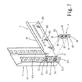
- FIG. 7 illustrates the mounting members of one support frame selectively inserted into the mounting holes of the front server frame before installation of the associating clamping plate according to the present invention.
- FIG. 8 corresponds to FIG. 7 , showing the clamping plate installed.
- FIG. 9 is a sectional assembly view in an enlarged scale of a part of the sliding rail assembly support frame and server frame mounting arrangement according to the present invention, showing one support frame fastened to the front server frame.
- FIG. 10 is an exploded view of the other support frame for the sliding rail assembly support frame and server frame mounting arrangement according to the present invention.
- FIG. 11 is an assembly view of FIG. 10 .
- FIG. 12 illustrates the mounting members of one support frame selectively inserted into the mounting holes of the rear server frame before installation of the associating clamping plate according to the present invention.
- FIG. 13 corresponds to FIG. 12 , showing the clamping plate installed.
- FIG. 14 is a sectional assembly view in an enlarged scale of a part of the sliding rail assembly support frame and server frame mounting arrangement according to the present invention, showing one support frame fastened to the rear server frame.
- FIG. 15 is an exploded view of a part of a second embodiment of the sliding rail assembly support frame and server frame mounting arrangement according to the present invention.
- FIG. 16 corresponds to FIG. 15 , showing the mounting members selectively inserted into the mounting holes of the front server frame.
- FIG. 17 corresponds to FIG. 16 , showing the clamping plate fastened to the mounting members.
- FIG. 18 is a sectional assembly view in an enlarged scale of a part of the second embodiment of the sliding rail assembly support frame and server frame mounting arrangement according to the present invention, showing the respective support frame fastened to the front server frame.
- the support frames 3 and 4 each have a flat frame base 30 or 40 , and a mounting flange 31 or 41 extended from one end of the flat frame base 30 or 40 at right angles.
- the flat frame base 30 of one support frame 3 has one longitudinal mounting slot 301 and a plurality of mounting holes 302 in line with the longitudinal mounting slot 301 .
- the flat frame base 40 of the other support frame 4 has two longitudinal mounting slots 401 longitudinally aligned in line.
- Fastening members 2 are mounted in the mounting slots 301 and 401 and the mounting holes 302 to affix the outer rail 11 to the support frames 3 and 4 .
- the mounting flanges 31 and 41 are selectively fastened to mounting holes 511 and 521 of front and rear server frames 51 and 52 . Further, the mounting flanges 31 and 41 of the support frames 3 and 4 each have a through hole 310 or 410 .
- the mounting flanges 31 and 41 of the support frames 3 and 4 each have mounted thereon at least two mounting members 311 or 411 .
- the mounting members 311 and 411 each have a cylindrical body 3111 or 4111 (see FIGS. 9 and 14 ), and a locating groove 3114 or 4114 extending around the periphery of the cylindrical body 3111 or 4111 (see FIGS. 5 and 10 ).
- the mounting members 311 and 411 are selectively inserted through the mounting holes 511 and 521 of the front and rear server frames 51 and 52 (see FIGS. 7 and 13 ).
- Each clamping plate 6 has at least two retaining notches 61 respectively forced into engagement with the locating groove 3114 or 4114 of the cylindrical bodies 3111 or 4111 of the mounting members 311 or 411 (see FIGS. 9 and 14 ).
- Each clamping plate 6 further has a protrusion 621 protruded from one sidewall 62 of each retaining notch 61 (see FIGS. 9 and 14 ).
- the sidewalls 62 of the respective retaining notches 61 are stretched outwards for allowing the respective protrusions 621 to move over the cylindrical bodies 3111 and 4111 of the respective mounting member 311 and 411 .
- the sidewalls 62 return to their former shape to hold the respective protrusions 621 in positive engagement with the cylindrical bodies 3111 and 4111 of the respective mounting member 311 and 411 , prohibiting backward displacement of the clamping plates 6 relative to the mounting members 311 and 411 .
- Each clamping plate 6 further includes an angled finger strip 63 at one side for positive gripping by hand, and a through hole 65 on the middle.
- the mounting member 311 and 411 may be formed integral with the mounting flanges 31 and 41 of the support frames 3 and 4 , or directly riveted to the mounting flanges 31 and 41 of the support frames 3 and 4 , or detachably secured to the mounting flanges 31 and 41 of the support frames 3 and 4 by any of a variety of known fastening means.
- the mounting flanges 31 and 41 of the support frames 3 and 4 each have a plurality of screw holes 312 or 412 (see FIGS. 5 and 10 ).
- the mounting members 311 and 411 each have a threaded shank 3112 or 4112 extended from one end of the cylindrical body 3111 or 4111 and respectively threaded into the screw holes 312 or 412 .
- each mounting member 311 or 411 further has a tool groove 3113 or 4113 on the other end opposite to the threaded shank 3112 or 4112 through which the respective mounting member 311 or 411 is rotatable with an air or electrical power hand tool.
- the tool groove 3113 or 4113 can be a straight groove, crossed groove, or hexagonal socket hole.
- FIGS. 15 ⁇ 18 show an alternate form of the present invention.
- This second embodiment is substantially similar to the aforesaid first embodiment.
- each clamping plate 6 ′ has a retaining notch 61 ′ at one end, a keyway 66 ′ at the other end (see FIG. 18 ), a protrusion 621 ′ protruded from one sidewall 62 ′ of the retaining notch 61 ′ (see FIG. 18 ), and two angled finger strips 63 ′, 64 ′ at two opposite sides (see FIGS. 15 and 16 ).
- the keyway 66 ′ is formed of a big hole and a small hole in communication with the big hole at one side.
- the small hole of the keyway 66 ′ has a diameter approximately equal to the diameter of the locating groove of the cylindrical body of each mounting member 3 .
- the big hole of the keyway 66 ′ has a diameter greater than the small hole.
- the clamping plate 6 ′ is hung on one mounting member 311 at the mounting flange 31 of the support frames 3 by means of the big hole of the keyway 66 ′, and then clamping plate 6 ′ is pulled in one direction to move the small hole of the keyway 66 ′ into coupling with the cylindrical body 3111 of the associating mounting member 311 , and then the clamping plate 6 ′ is turned about the associating mounting member 311 to force the retaining notch 61 ′ into engagement with the locating groove 3114 of the cylindrical body 3111 of the other mounting member 311 at the mounting flange 31 of the support frames 3 (see FIG. 17 ).
- the protrusion 621 ′ is forced into engagement with the cylindrical body 3111 of the associating mounting member 311 to prohibit displacement of the clamping plate 6 ′ relative to the mounting flange 31 of the support frames 3 .
- the invention has the following advantages:
- the mounting members 311 and 411 at the mounting flanges 31 and 41 of the support frames 3 and 4 being respectively fastened to the front and rear ends of the outer rail 11 of the sliding rail assembly 1 can be selectively inserted through the mounting holes 511 and 521 of the front and rear server frames 51 and 52 of the server frame unit 5 and then secured thereto with the clamping plates 6 . This mounting procedure saves much labor and time.
- the clamping plates 6 each have an angled finger strip 63 for positive gripping with the hand. Therefore, the clamping plates 6 can easily be installed without tools.
Abstract
Description
- 1. Because two sliding
rail assemblies 7 must be installed in theserver frame unit 9 at two sides, totally 12 screws are necessary to affix themounting holes support frames rear server frames 91 of theserver frame unit 9. Therefore, the installation of the sliding rail assembly support frame and server frame mounting arrangement requires much labor and time. - 2. Because sliding sleeves with balls are provided among the inner sliding
rail 73, intermediate slidingrail 72 andouter rail 71 of each slidingrail assembly 7, the inner slidingrail 73 or intermediate slidingrail 72 may slide over themounting flange support frame 81 or 82 (seeFIGS. 1 and 3 ) if thesupport frame mounting screws
Claims (8)
Priority Applications (1)
| Application Number | Priority Date | Filing Date | Title |
|---|---|---|---|
| US11/657,123 US7780253B1 (en) | 2007-01-24 | 2007-01-24 | Sliding rail assembly support frame and server frame mounting arrangement |
Applications Claiming Priority (1)
| Application Number | Priority Date | Filing Date | Title |
|---|---|---|---|
| US11/657,123 US7780253B1 (en) | 2007-01-24 | 2007-01-24 | Sliding rail assembly support frame and server frame mounting arrangement |
Publications (1)
| Publication Number | Publication Date |
|---|---|
| US7780253B1 true US7780253B1 (en) | 2010-08-24 |
Family
ID=42583264
Family Applications (1)
| Application Number | Title | Priority Date | Filing Date |
|---|---|---|---|
| US11/657,123 Active 2028-05-12 US7780253B1 (en) | 2007-01-24 | 2007-01-24 | Sliding rail assembly support frame and server frame mounting arrangement |
Country Status (1)
| Country | Link |
|---|---|
| US (1) | US7780253B1 (en) |
Cited By (20)
| Publication number | Priority date | Publication date | Assignee | Title |
|---|---|---|---|---|
| US20090219701A1 (en) * | 2008-02-29 | 2009-09-03 | Sui-An Wu | Sliding flat panel display and keyboard module |
| US20100007255A1 (en) * | 2008-07-08 | 2010-01-14 | Chi-Tsun Cheng | Rail set assembly for a machine casing of the industrial computer |
| US20100101391A1 (en) * | 2008-10-27 | 2010-04-29 | Rexon Industrial Corp., Ltd. | Quick-release mechanism for saw machine |
| US20100314337A1 (en) * | 2009-06-12 | 2010-12-16 | Hon Hai Precision Industry Co., Ltd. | Server rack assembly |
| US20110091141A1 (en) * | 2008-10-16 | 2011-04-21 | Chien-Fa Liang | Ultrathin Slide Rail Capable of Rapid Installation and Removal |
| US20110194910A1 (en) * | 2010-02-09 | 2011-08-11 | Hong Fu Jin Precision Industry (Shenzhen) Co., Ltd . | Assembly having screw and nut |
| US8534775B1 (en) * | 2012-03-08 | 2013-09-17 | Hong Fu Jin Precision Industry (Shenzhen) Co., Ltd. | Server cabinet |
| US20140339975A1 (en) * | 2013-05-14 | 2014-11-20 | Hon Hai Precision Industry Co., Ltd. | Slide assembly |
| US20150090679A1 (en) * | 2013-09-30 | 2015-04-02 | Fmr Llc | Open bridge rack |
| CN104503548A (en) * | 2014-12-03 | 2015-04-08 | 英业达科技有限公司 | Server |
| USD733531S1 (en) * | 2013-09-26 | 2015-07-07 | Innovation First, Inc. | Bracket |
| US9229492B2 (en) | 2012-10-18 | 2016-01-05 | Dell Products L.P. | Adaptive information handling system rack rail mount |
| US9456520B1 (en) * | 2015-09-25 | 2016-09-27 | Innovation First, Inc. | Server rack system for mounting equipment |
| US9814156B2 (en) | 2015-09-25 | 2017-11-07 | Innovation First, Inc. | Server rack system for mounting equipment |
| US20180084908A1 (en) * | 2016-09-24 | 2018-03-29 | King Slide Works Co., Ltd. | Bracket device |
| CN108153385A (en) * | 2018-03-23 | 2018-06-12 | 电子科技大学中山学院 | Server terminal for campus cloud platform |
| WO2018102838A1 (en) * | 2016-12-05 | 2018-06-14 | Patchbox Gmbh | Securing element |
| USD837037S1 (en) * | 2017-03-24 | 2019-01-01 | Lennox Industries Inc. | Support bracket |
| USD884461S1 (en) * | 2019-03-12 | 2020-05-19 | Peter Allen | Bracket for retaining an air-conditioner located within a window frame |
| US20230092329A1 (en) * | 2021-09-20 | 2023-03-23 | Dell Products L.P. | Top of Stack Safety Rail |
Citations (26)
| Publication number | Priority date | Publication date | Assignee | Title |
|---|---|---|---|---|
| US2698762A (en) * | 1950-11-22 | 1955-01-04 | Houdaille Hershey Corp | Latch release mechanism |
| US2946546A (en) * | 1959-12-31 | 1960-07-26 | Pokorny Louis | Fishing rod support |
| US3401968A (en) * | 1966-06-23 | 1968-09-17 | Excelsior Hardware Company | Cam actuated latch |
| US3696774A (en) * | 1969-11-04 | 1972-10-10 | Kvaerner Brug As | Battening system for hatch covers |
| US3888528A (en) * | 1972-05-08 | 1975-06-10 | Von Tell Trading Co Ab | Hatch battening device |
| US3986318A (en) * | 1974-09-30 | 1976-10-19 | Interlake, Inc. | Structural member and assembly thereof |
| US4474492A (en) * | 1982-09-30 | 1984-10-02 | Bestop/Dualmatic, Inc. | Self-locking spare tire carrier latch |
| US4919557A (en) * | 1988-10-14 | 1990-04-24 | Dennison Manufacturing Company | Looseleaf binder with sliding lock mechanism |
| US5791498A (en) * | 1997-01-21 | 1998-08-11 | Dell U.S.A., L.P. | Rack mount mechanism having an angled bar-nut |
| US6260810B1 (en) * | 1999-08-16 | 2001-07-17 | Dong-A Flexible Metal Tubes Co., Ltd. | Sprinkler mounting device |
| US6273534B1 (en) * | 1999-11-05 | 2001-08-14 | Spacesaver Corporation | Shelving accessory mounting system for a cabinet assembly |
| US6315336B1 (en) * | 2000-05-30 | 2001-11-13 | Summit Manufacturing, Inc. | Motorized self-cleaning oven latch |
| US6523918B1 (en) * | 2001-04-24 | 2003-02-25 | Central Industrial Supply Company, Inc. | Pivot mounting bracket with toolless fastener for a server rack |
| US20030106864A1 (en) * | 2001-12-10 | 2003-06-12 | Kaminski Joseph W. | Rack assembly that does not require tools for coupling slides together |
| US20030107309A1 (en) * | 2001-12-06 | 2003-06-12 | Lauchner Craig E. | Dual flat springs for tool-less slide installation |
| US6622873B2 (en) * | 2001-06-20 | 2003-09-23 | International Business Machines Corporation | Self-aligning, single person installable rack rail/alignment plate assembly |
| US6736277B2 (en) * | 2002-03-11 | 2004-05-18 | Hewlett-Packard Development Company, L.P. | Adjustable rackmount assembly |
| US20040219807A1 (en) * | 2003-01-09 | 2004-11-04 | Weiss Roger E | Apparatus for applying a mechanically-releasable balanced compressive load to an assembly such as a complaint anisotropic conductive elastomer electrical connector |
| US6840388B2 (en) * | 2002-10-28 | 2005-01-11 | Hewlett-Packard Development Company, L.P. | Tool-less rack mounting system |
| US6854611B2 (en) * | 2002-02-01 | 2005-02-15 | Excel Storage Products, Inc. | Lock for preventing inadvertent removal of a first frame component of an adjustable storage system from a second frame component of the adjustable storage system and the adjustable storage system |
| US20050156493A1 (en) * | 2003-12-30 | 2005-07-21 | Shun-Ho Yang | Bracket positioning structure for a slide |
| US6926378B2 (en) * | 2002-08-15 | 2005-08-09 | General Devices Co., Inc. | Support system for telescoping slide assembly |
| US6929336B2 (en) * | 2003-03-28 | 2005-08-16 | Hon Hai Precision Ind. Co., Ltd. | Retaining assembly for rack cabinet |
| US20050285492A1 (en) * | 2004-06-28 | 2005-12-29 | Tatung Co., Ltd. | Sliding rail mounting structure |
| US7012808B2 (en) * | 2002-12-20 | 2006-03-14 | Hewlett-Packard Development Company, L.P. | Multi-configurable telecommunications rack mounting system and method incorporating same |
| US7281694B2 (en) * | 2004-06-14 | 2007-10-16 | Hewlett-Packard Development Company, L.P. | Mounting bracket |
-
2007
- 2007-01-24 US US11/657,123 patent/US7780253B1/en active Active
Patent Citations (27)
| Publication number | Priority date | Publication date | Assignee | Title |
|---|---|---|---|---|
| US2698762A (en) * | 1950-11-22 | 1955-01-04 | Houdaille Hershey Corp | Latch release mechanism |
| US2946546A (en) * | 1959-12-31 | 1960-07-26 | Pokorny Louis | Fishing rod support |
| US3401968A (en) * | 1966-06-23 | 1968-09-17 | Excelsior Hardware Company | Cam actuated latch |
| US3696774A (en) * | 1969-11-04 | 1972-10-10 | Kvaerner Brug As | Battening system for hatch covers |
| US3888528A (en) * | 1972-05-08 | 1975-06-10 | Von Tell Trading Co Ab | Hatch battening device |
| US3986318A (en) * | 1974-09-30 | 1976-10-19 | Interlake, Inc. | Structural member and assembly thereof |
| US4474492A (en) * | 1982-09-30 | 1984-10-02 | Bestop/Dualmatic, Inc. | Self-locking spare tire carrier latch |
| US4919557A (en) * | 1988-10-14 | 1990-04-24 | Dennison Manufacturing Company | Looseleaf binder with sliding lock mechanism |
| US5791498A (en) * | 1997-01-21 | 1998-08-11 | Dell U.S.A., L.P. | Rack mount mechanism having an angled bar-nut |
| US6260810B1 (en) * | 1999-08-16 | 2001-07-17 | Dong-A Flexible Metal Tubes Co., Ltd. | Sprinkler mounting device |
| US6273534B1 (en) * | 1999-11-05 | 2001-08-14 | Spacesaver Corporation | Shelving accessory mounting system for a cabinet assembly |
| US6315336B1 (en) * | 2000-05-30 | 2001-11-13 | Summit Manufacturing, Inc. | Motorized self-cleaning oven latch |
| US6523918B1 (en) * | 2001-04-24 | 2003-02-25 | Central Industrial Supply Company, Inc. | Pivot mounting bracket with toolless fastener for a server rack |
| US6622873B2 (en) * | 2001-06-20 | 2003-09-23 | International Business Machines Corporation | Self-aligning, single person installable rack rail/alignment plate assembly |
| US20030107309A1 (en) * | 2001-12-06 | 2003-06-12 | Lauchner Craig E. | Dual flat springs for tool-less slide installation |
| US6830300B2 (en) * | 2001-12-06 | 2004-12-14 | Hewlett-Packard Development Company, L.P. | Dual flat springs for tool-less slide installation |
| US20030106864A1 (en) * | 2001-12-10 | 2003-06-12 | Kaminski Joseph W. | Rack assembly that does not require tools for coupling slides together |
| US6854611B2 (en) * | 2002-02-01 | 2005-02-15 | Excel Storage Products, Inc. | Lock for preventing inadvertent removal of a first frame component of an adjustable storage system from a second frame component of the adjustable storage system and the adjustable storage system |
| US6736277B2 (en) * | 2002-03-11 | 2004-05-18 | Hewlett-Packard Development Company, L.P. | Adjustable rackmount assembly |
| US6926378B2 (en) * | 2002-08-15 | 2005-08-09 | General Devices Co., Inc. | Support system for telescoping slide assembly |
| US6840388B2 (en) * | 2002-10-28 | 2005-01-11 | Hewlett-Packard Development Company, L.P. | Tool-less rack mounting system |
| US7012808B2 (en) * | 2002-12-20 | 2006-03-14 | Hewlett-Packard Development Company, L.P. | Multi-configurable telecommunications rack mounting system and method incorporating same |
| US20040219807A1 (en) * | 2003-01-09 | 2004-11-04 | Weiss Roger E | Apparatus for applying a mechanically-releasable balanced compressive load to an assembly such as a complaint anisotropic conductive elastomer electrical connector |
| US6929336B2 (en) * | 2003-03-28 | 2005-08-16 | Hon Hai Precision Ind. Co., Ltd. | Retaining assembly for rack cabinet |
| US20050156493A1 (en) * | 2003-12-30 | 2005-07-21 | Shun-Ho Yang | Bracket positioning structure for a slide |
| US7281694B2 (en) * | 2004-06-14 | 2007-10-16 | Hewlett-Packard Development Company, L.P. | Mounting bracket |
| US20050285492A1 (en) * | 2004-06-28 | 2005-12-29 | Tatung Co., Ltd. | Sliding rail mounting structure |
Cited By (31)
| Publication number | Priority date | Publication date | Assignee | Title |
|---|---|---|---|---|
| US20090219701A1 (en) * | 2008-02-29 | 2009-09-03 | Sui-An Wu | Sliding flat panel display and keyboard module |
| US20100007255A1 (en) * | 2008-07-08 | 2010-01-14 | Chi-Tsun Cheng | Rail set assembly for a machine casing of the industrial computer |
| US8292382B2 (en) * | 2008-07-08 | 2012-10-23 | Lif J. K. Corporation | Rail set assembly for a machine casing of the industrial computer |
| US8033621B2 (en) * | 2008-10-16 | 2011-10-11 | Ablecom Technology Incorporation | Ultrathin slide rail capable of rapid installation and removal |
| US20110091141A1 (en) * | 2008-10-16 | 2011-04-21 | Chien-Fa Liang | Ultrathin Slide Rail Capable of Rapid Installation and Removal |
| US20100101391A1 (en) * | 2008-10-27 | 2010-04-29 | Rexon Industrial Corp., Ltd. | Quick-release mechanism for saw machine |
| US20100314337A1 (en) * | 2009-06-12 | 2010-12-16 | Hon Hai Precision Industry Co., Ltd. | Server rack assembly |
| US8356718B2 (en) * | 2009-06-12 | 2013-01-22 | Hon Hai Precision Industry Co., Ltd. | Server rack assembly |
| US20110194910A1 (en) * | 2010-02-09 | 2011-08-11 | Hong Fu Jin Precision Industry (Shenzhen) Co., Ltd . | Assembly having screw and nut |
| US8534775B1 (en) * | 2012-03-08 | 2013-09-17 | Hong Fu Jin Precision Industry (Shenzhen) Co., Ltd. | Server cabinet |
| US9750155B2 (en) | 2012-10-18 | 2017-08-29 | Dell Products L.P. | Adaptive information handling system rack rail mount |
| US9229492B2 (en) | 2012-10-18 | 2016-01-05 | Dell Products L.P. | Adaptive information handling system rack rail mount |
| US20140339975A1 (en) * | 2013-05-14 | 2014-11-20 | Hon Hai Precision Industry Co., Ltd. | Slide assembly |
| USD759466S1 (en) | 2013-09-26 | 2016-06-21 | Innovation First, Inc. | Bracket |
| USD733531S1 (en) * | 2013-09-26 | 2015-07-07 | Innovation First, Inc. | Bracket |
| US9131769B2 (en) * | 2013-09-30 | 2015-09-15 | Fmr Llc | Open bridge rack |
| US20150090679A1 (en) * | 2013-09-30 | 2015-04-02 | Fmr Llc | Open bridge rack |
| US9363920B1 (en) * | 2014-12-03 | 2016-06-07 | Inventec (Pudong) Technology Corporation | Server |
| CN104503548A (en) * | 2014-12-03 | 2015-04-08 | 英业达科技有限公司 | Server |
| CN104503548B (en) * | 2014-12-03 | 2017-12-05 | 英业达科技有限公司 | Server |
| US9456520B1 (en) * | 2015-09-25 | 2016-09-27 | Innovation First, Inc. | Server rack system for mounting equipment |
| US9814156B2 (en) | 2015-09-25 | 2017-11-07 | Innovation First, Inc. | Server rack system for mounting equipment |
| US20180084908A1 (en) * | 2016-09-24 | 2018-03-29 | King Slide Works Co., Ltd. | Bracket device |
| US10251482B2 (en) * | 2016-09-24 | 2019-04-09 | King Slide Works Co., Ltd. | Bracket device |
| WO2018102838A1 (en) * | 2016-12-05 | 2018-06-14 | Patchbox Gmbh | Securing element |
| CN110234894A (en) * | 2016-12-05 | 2019-09-13 | 接线盒有限公司 | Tightening member |
| USD837037S1 (en) * | 2017-03-24 | 2019-01-01 | Lennox Industries Inc. | Support bracket |
| CN108153385A (en) * | 2018-03-23 | 2018-06-12 | 电子科技大学中山学院 | Server terminal for campus cloud platform |
| USD884461S1 (en) * | 2019-03-12 | 2020-05-19 | Peter Allen | Bracket for retaining an air-conditioner located within a window frame |
| US20230092329A1 (en) * | 2021-09-20 | 2023-03-23 | Dell Products L.P. | Top of Stack Safety Rail |
| US11844190B2 (en) * | 2021-09-20 | 2023-12-12 | Dell Products L.P. | Top of stack safety rail |
Similar Documents
| Publication | Publication Date | Title |
|---|---|---|
| US7780253B1 (en) | Sliding rail assembly support frame and server frame mounting arrangement | |
| US7878468B2 (en) | Slide bracket | |
| US9718410B2 (en) | Assembly for connecting a roof rack to a vehicle | |
| US7669723B2 (en) | Tool suspension device | |
| US9597792B1 (en) | Hand tool hanger | |
| EP2641514B1 (en) | Wall hanging fixing device and wall hanging bathroom articles | |
| US20110173759A1 (en) | Bicycle tool assembly | |
| CN102672634A (en) | Clamping mechanism | |
| US20020117029A1 (en) | Pliers | |
| CN106969300B (en) | Ceiling lamp | |
| US7387544B1 (en) | Lamp socket adapter to convert a screw type socket into a slot type socket irreversibly | |
| JP5534639B2 (en) | desk | |
| CN211916583U (en) | Workpiece clamping device capable of freely adjusting clamping height | |
| CN210327497U (en) | Photovoltaic terminal box positioning fixture | |
| CN218029887U (en) | Buckle convenient to install | |
| CN218995985U (en) | Hard disk bracket structure free of screw | |
| CN211441634U (en) | Locking device and printer | |
| CN212045804U (en) | Center thimble quick change device for injection molding machine | |
| CN215475712U (en) | Unmanned aerial vehicle foot rest and unmanned aerial vehicle | |
| CN212431068U (en) | Air conditioner | |
| CN211977695U (en) | Quick release device of rifle lamp and tail switch | |
| CN218266630U (en) | Connecting assembly | |
| CN214170200U (en) | Clamping type base-free handle | |
| US20080043476A1 (en) | Fastening device for the fastening of attachment parts | |
| CN215367579U (en) | Bench installation component and faucet |
Legal Events
| Date | Code | Title | Description |
|---|---|---|---|
| AS | Assignment |
Owner name: GSLIDE CORPORATION, TAIWAN Free format text: ASSIGNMENT OF ASSIGNORS INTEREST;ASSIGNOR:LU, CHUN-MIN;REEL/FRAME:018830/0251 Effective date: 20070110 |
|
| STCF | Information on status: patent grant |
Free format text: PATENTED CASE |
|
| FPAY | Fee payment |
Year of fee payment: 4 |
|
| MAFP | Maintenance fee payment |
Free format text: PAYMENT OF MAINTENANCE FEE, 8TH YEAR, LARGE ENTITY (ORIGINAL EVENT CODE: M1552) Year of fee payment: 8 |
|
| MAFP | Maintenance fee payment |
Free format text: PAYMENT OF MAINTENANCE FEE, 12TH YEAR, LARGE ENTITY (ORIGINAL EVENT CODE: M1553); ENTITY STATUS OF PATENT OWNER: LARGE ENTITY Year of fee payment: 12 |