US7766374B2 - Vehicle occupant restraint device comprising a gas bag - Google Patents
Vehicle occupant restraint device comprising a gas bag Download PDFInfo
- Publication number
- US7766374B2 US7766374B2 US11/788,898 US78889807A US7766374B2 US 7766374 B2 US7766374 B2 US 7766374B2 US 78889807 A US78889807 A US 78889807A US 7766374 B2 US7766374 B2 US 7766374B2
- Authority
- US
- United States
- Prior art keywords
- gas bag
- control element
- restraint device
- occupant restraint
- vehicle occupant
- Prior art date
- Legal status (The legal status is an assumption and is not a legal conclusion. Google has not performed a legal analysis and makes no representation as to the accuracy of the status listed.)
- Active, expires
Links
- 210000003127 knee Anatomy 0.000 claims description 5
- 230000000452 restraining effect Effects 0.000 claims 2
- 230000000694 effects Effects 0.000 description 6
- 230000001276 controlling effect Effects 0.000 description 4
- 239000004744 fabric Substances 0.000 description 3
- 210000002414 leg Anatomy 0.000 description 3
- 239000002184 metal Substances 0.000 description 3
- 230000008093 supporting effect Effects 0.000 description 3
- 230000006978 adaptation Effects 0.000 description 2
- 238000009434 installation Methods 0.000 description 2
- 230000002452 interceptive effect Effects 0.000 description 2
- 239000000463 material Substances 0.000 description 2
- 208000029152 Small face Diseases 0.000 description 1
- 238000010521 absorption reaction Methods 0.000 description 1
- 238000004519 manufacturing process Methods 0.000 description 1
- 238000000034 method Methods 0.000 description 1
- 230000000284 resting effect Effects 0.000 description 1
- 238000007493 shaping process Methods 0.000 description 1
- 238000004904 shortening Methods 0.000 description 1
- 230000006641 stabilisation Effects 0.000 description 1
- 238000011105 stabilization Methods 0.000 description 1
Images


Classifications
-
- B—PERFORMING OPERATIONS; TRANSPORTING
- B60—VEHICLES IN GENERAL
- B60R—VEHICLES, VEHICLE FITTINGS, OR VEHICLE PARTS, NOT OTHERWISE PROVIDED FOR
- B60R21/00—Arrangements or fittings on vehicles for protecting or preventing injuries to occupants or pedestrians in case of accidents or other traffic risks
- B60R21/02—Occupant safety arrangements or fittings, e.g. crash pads
- B60R21/16—Inflatable occupant restraints or confinements designed to inflate upon impact or impending impact, e.g. air bags
- B60R21/23—Inflatable members
- B60R21/231—Inflatable members characterised by their shape, construction or spatial configuration
-
- B—PERFORMING OPERATIONS; TRANSPORTING
- B60—VEHICLES IN GENERAL
- B60R—VEHICLES, VEHICLE FITTINGS, OR VEHICLE PARTS, NOT OTHERWISE PROVIDED FOR
- B60R21/00—Arrangements or fittings on vehicles for protecting or preventing injuries to occupants or pedestrians in case of accidents or other traffic risks
- B60R21/02—Occupant safety arrangements or fittings, e.g. crash pads
- B60R21/16—Inflatable occupant restraints or confinements designed to inflate upon impact or impending impact, e.g. air bags
- B60R21/20—Arrangements for storing inflatable members in their non-use or deflated condition; Arrangement or mounting of air bag modules or components
- B60R21/205—Arrangements for storing inflatable members in their non-use or deflated condition; Arrangement or mounting of air bag modules or components in dashboards
- B60R21/206—Arrangements for storing inflatable members in their non-use or deflated condition; Arrangement or mounting of air bag modules or components in dashboards in the lower part of dashboards, e.g. for protecting the knees
-
- B—PERFORMING OPERATIONS; TRANSPORTING
- B60—VEHICLES IN GENERAL
- B60R—VEHICLES, VEHICLE FITTINGS, OR VEHICLE PARTS, NOT OTHERWISE PROVIDED FOR
- B60R21/00—Arrangements or fittings on vehicles for protecting or preventing injuries to occupants or pedestrians in case of accidents or other traffic risks
- B60R21/02—Occupant safety arrangements or fittings, e.g. crash pads
- B60R21/16—Inflatable occupant restraints or confinements designed to inflate upon impact or impending impact, e.g. air bags
- B60R21/23—Inflatable members
- B60R21/231—Inflatable members characterised by their shape, construction or spatial configuration
- B60R21/2334—Expansion control features
- B60R21/2338—Tethers
-
- B—PERFORMING OPERATIONS; TRANSPORTING
- B60—VEHICLES IN GENERAL
- B60R—VEHICLES, VEHICLE FITTINGS, OR VEHICLE PARTS, NOT OTHERWISE PROVIDED FOR
- B60R21/00—Arrangements or fittings on vehicles for protecting or preventing injuries to occupants or pedestrians in case of accidents or other traffic risks
- B60R21/02—Occupant safety arrangements or fittings, e.g. crash pads
- B60R21/16—Inflatable occupant restraints or confinements designed to inflate upon impact or impending impact, e.g. air bags
- B60R21/23—Inflatable members
- B60R21/231—Inflatable members characterised by their shape, construction or spatial configuration
- B60R2021/23176—Inflatable members characterised by their shape, construction or spatial configuration specially adapted for foot protection
-
- B—PERFORMING OPERATIONS; TRANSPORTING
- B60—VEHICLES IN GENERAL
- B60R—VEHICLES, VEHICLE FITTINGS, OR VEHICLE PARTS, NOT OTHERWISE PROVIDED FOR
- B60R21/00—Arrangements or fittings on vehicles for protecting or preventing injuries to occupants or pedestrians in case of accidents or other traffic risks
- B60R21/02—Occupant safety arrangements or fittings, e.g. crash pads
- B60R21/16—Inflatable occupant restraints or confinements designed to inflate upon impact or impending impact, e.g. air bags
- B60R21/23—Inflatable members
- B60R21/231—Inflatable members characterised by their shape, construction or spatial configuration
- B60R21/2334—Expansion control features
- B60R21/2338—Tethers
- B60R2021/23382—Internal tether means
-
- B—PERFORMING OPERATIONS; TRANSPORTING
- B60—VEHICLES IN GENERAL
- B60R—VEHICLES, VEHICLE FITTINGS, OR VEHICLE PARTS, NOT OTHERWISE PROVIDED FOR
- B60R21/00—Arrangements or fittings on vehicles for protecting or preventing injuries to occupants or pedestrians in case of accidents or other traffic risks
- B60R21/02—Occupant safety arrangements or fittings, e.g. crash pads
- B60R21/16—Inflatable occupant restraints or confinements designed to inflate upon impact or impending impact, e.g. air bags
- B60R21/23—Inflatable members
- B60R21/231—Inflatable members characterised by their shape, construction or spatial configuration
- B60R21/2334—Expansion control features
- B60R21/2338—Tethers
- B60R2021/23386—External tether means
-
- B—PERFORMING OPERATIONS; TRANSPORTING
- B60—VEHICLES IN GENERAL
- B60R—VEHICLES, VEHICLE FITTINGS, OR VEHICLE PARTS, NOT OTHERWISE PROVIDED FOR
- B60R21/00—Arrangements or fittings on vehicles for protecting or preventing injuries to occupants or pedestrians in case of accidents or other traffic risks
- B60R21/02—Occupant safety arrangements or fittings, e.g. crash pads
- B60R21/16—Inflatable occupant restraints or confinements designed to inflate upon impact or impending impact, e.g. air bags
- B60R21/20—Arrangements for storing inflatable members in their non-use or deflated condition; Arrangement or mounting of air bag modules or components
- B60R21/205—Arrangements for storing inflatable members in their non-use or deflated condition; Arrangement or mounting of air bag modules or components in dashboards
Definitions
- the invention relates to a vehicle occupant restraint device comprising a gas bag.
- Gas bags are provided in vehicles for the protection of vehicle occupants during crash situations. It is important that they take up their inflated position as fast as possible, even if the gas bag module has to be arranged in an inconvenient position due to the design of the vehicle.
- a vehicle occupant restraint device has a gas bag module with a housing and a gas bag having a free exit end, the gas bag moving into its fully deployed position with the free exit end first.
- At least one control element is provided which engages the gas bag and forces the gas bag to extend in the deployed state generally in an arc shape from the housing up to the free exit end.
- the control element can also affect the deploying motion of the gas bag, such that the deploying motion proceeds in an arc shape and the direction of motion of the front part of the gas bag thus varies during deployment.
- the invention is particularly suitable if the deployment takes place at least partially opposite to the direction of the gravitational force, i.e. upwards, as can be the case for example in knee protection gas bags.
- the invention is particularly advantageous for gas bag modules in which the gas bag is not deployed directly towards the body part that needs to be restrained but in which the gas bag, in particular its free, front exit end describes, so to speak, a curve during deployment.
- control element is a limiting strap.
- the control element preferably engages a rear-side shell part of the gas bag.
- the control element can for example be formed by a limiting strap engaging the rear-side shell part and a front-side shell part of the gas bag, the fastening points of the limiting strap being offset with respect to each other in the deployment direction of the gas bag.
- control element engages a vehicle-fixed component, forming for example an abutment about which the gas bag pivots during deployment. This arrangement further contributes to the fact that the gas bag is held in its shape and position in the deployed state.
- the fastening of the control element to the vehicle-fixed component can be realized in any suitable manner.
- a loop of the control element can for example be secured to the vehicle-fixed component.
- Hooks for securing the control element can also be provided on the vehicle-fixed component.
- control element can be clamped to the vehicle-fixed component.
- control element it is also possible to secure the control element to the vehicle-fixed component by means of a screw connection.
- An essentially rigid fastening part which is preferably secured directly to the vehicle-fixed component can also be arranged inside or outside the gas bag as a control element.
- control element is arranged completely outside the gas bag.
- control element extends inside the gas bag.
- control elements which may also differ from each other, can be provided. These can be used alternatively or additionally to the control element types described so far.
- Limiting straps connecting the rear-side shell part and the front-side shell part of the gas bag to each other, which are arranged in the region of a vehicle contour and which adapt the shape of the gas bag to the vehicle contour can also be provided as control elements.
- a housing for receiving the folded gas bag, and the housing has a bottom which bulges when the gas bag exits the housing. Particularly in very flat housing shapes, this permits a purposeful absorption of the forces occurring during deployment.
- the bottom and an edge of the bottom delimiting an exit opening can also be used to transmit to the gas bag, in the initial stage of its deployment, an impulse from this face that may be upwards directed, opposite to the gravitational force.
- the gas bag can be supported by the bottom and can for example thus obtain its curved shape more rapidly.
- the bottom is thus to be considered to be a control element, too.
- control elements giving the shape or controlling the motion and which support the gas bag such that it assumes a predetermined position and/or a predetermined shape during its deployment are provided.
- the control elements can engage both the gas bag and vehicle-fixed components but can also be provided only on the gas bag.
- the control elements can be arranged both inside the gas bag and on the outside of the gas bag.
- the control elements can be shape-determining control elements arranged inside the gas bag or on the gas bag and which permit an adaptation of the shape of the gas bag in three dimensions.
- the gas bag In the inflated state, the gas bag can thus be adapted to the contour of e.g. an adjoining lining part. Furthermore, it can also be held opposite to the gravitational force in a predetermined position, for example resting on the lining part.
- control elements can also have a motion controlling effect by means of which during the deployment, the gas bag follows a curved line, for example avoiding an interfering vehicle contour.
- the invention can be used for gas bags in all positions in a vehicle, for example for knee protection gas bags, side gas bags, in particular those which deploy from a back rest of a vehicle seat, or for front gas bags for the driver and the passenger.
- FIG. 1 shows a schematic representation of a vehicle occupant restraint device according to the invention during the deployment of the gas bag
- FIG. 2 shows the vehicle occupant restraint device of FIG. 1 with the gas bag fully deployed
- FIG. 3 shows a schematic sectional view of a first embodiment of a vehicle occupant restraint device according to the invention
- FIG. 4 shows a detail of the vehicle occupant restraint device of FIG. 3 in a perspective view
- FIG. 5 shows a schematic sectional view of a second embodiment of a vehicle occupant restraint device according to the invention
- FIG. 6 shows the vehicle occupant restraint device of FIG. 5 in a perspective view
- FIG. 7 shows a variant of the vehicle occupant restraint device of FIGS. 5 and 6 in a perspective view
- FIG. 8 shows a schematic sectional view of a third embodiment of a vehicle occupant restraint device according to the invention.
- FIG. 9 shows the vehicle occupant restraint device of FIG. 8 in a perspective view
- FIG. 10 shows a schematic sectional view of a fourth embodiment of a vehicle occupant restraint device according to the invention.
- FIG. 11 shows the vehicle occupant restraint device of FIG. 10 in a perspective view
- FIG. 12 shows a schematic and perspective sectional view of a fifth embodiment of a vehicle occupant restraint device according to the invention.
- FIG. 13 shows a schematic sectional view of a sixth embodiment of a vehicle occupant restraint device according to the invention.
- FIG. 14 shows a detail of the vehicle occupant restraint device of FIG. 13 in a perspective view
- FIG. 15 shows a schematic sectional view of a seventh embodiment of a vehicle occupant restraint device according to the invention.
- FIG. 16 shows a perspective view of a eighth embodiment of the vehicle occupant restraint device according to the invention.
- FIG. 17 shows a schematic sectional view of a ninth embodiment of a vehicle occupant restraint device according to the invention.
- FIG. 18 shows the vehicle occupant restraint device of FIG. 17 in a perspective view
- FIG. 19 shows a schematic and perspective view of a tenth embodiment of a vehicle occupant restraint device according to the invention.
- FIG. 20 shows the vehicle occupant restraint device of FIG. 19 in a schematic sectional view
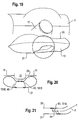
- FIG. 21 shows a schematic sectional view of a detail of a vehicle occupant restraint device according to the invention, in which a control element is arranged with an offset in the gas bag;
- FIGS. 22 a and 22 b show two different views of a housing of a vehicle occupant restraint device according to the invention before the deployment of the gas bag;
- FIGS. 23 a and 23 b show two different views of the housing of FIG. 22 during the deployment of the gas bag.
- the figures represent a vehicle occupant restraint device 1 comprising a gas bag module and in which a knee protection gas bag is shown as an example for all gas bag types which can be used.
- FIGS. 1 and 2 show the functional principle of the invention.
- FIG. 1 shows the vehicle occupant restraint device 1 during the deployment of its gas bag 10
- FIG. 2 shows the fully deployed gas bag 10 in its final position in which its rests against a vehicle contour.
- the gas bag 10 Prior to its deployment, the gas bag 10 is received in a folded state in a housing 14 , below a dashboard 11 , here also below a steering wheel 13 and a steering column lining 12 .
- the housing 14 could also be reduced to a supporting or fastening element for fixing the gas bag module to a vehicle-fixed component.
- the gas bag 10 When the gas bag 10 is actuated, it is inflated by gas discharged from a gas generator 16 which is fastened to the housing 14 by means of threaded bolts projecting from the gas generator 16 . The gas bag then deploys out of the housing 14 into the position shown in FIG. 2 , a free, front exit end 17 leading its motion.
- the aim is to protect the legs of the vehicle occupant and to obtain a stabilization of the position of the vehicle occupant by means of the gas bag 10 .
- the housing 14 is arranged at some distance below the highest point of the deployed gas bag 10 , which is approximately coincident with the free exit end 17 of the gas bag 10 .
- the gas bag 10 In its fully deployed state, the gas bag 10 has a three-dimensional shape curved upwards in an arc shape (cf. FIG. 2 , for example). Due to this shape, the gas bag rests against the vehicle contour of the dashboard 11 , which also extends in a curve.
- the curvature of the dashboard 11 and of the steering column lining 12 has the effect that the gas bag 10 can not deploy in a direct line.
- the deployment direction R of the gas bag 10 is not in a straight line, either, but also extends upwards in an arc shape (cf. FIG. 1 ).
- the three-dimensional curved shape as well as the curved deploying motion are determined, along with other parameters, by one or more control elements 18 , 618 , 918 , 1018 , 1118 .
- Each control element 18 , 618 , 918 , 1018 , 1118 has an effect determining the shape, the position and/or the direction of the gas bag 10 and is arranged inside and/or on the outside of the gas bag 10 and of the housing 14 , respectively.
- the control element 18 serves to obtain, during deployment, an upwardly directed movement of the gas bag 10 and a curvature towards a rear-side shell part 20 of the gas bag 10 by shortening and retaining, respectively, the rear-side shell part 20 of the gas bag 10 .
- the gas bag 10 shown is structured with known limiting straps 19 which are arranged in its interior, each extending between the rear-side shell part 20 and a front-side shell part 21 and being sewn to the shell parts 20 , 21 or fastened in any other suitable manner.
- control element 18 is formed by a limiting strap which is arranged completely outside the gas bag 10 .
- One end of the limiting strap engages the rear-side shell part 20 of the gas bag 10 and the other end engages a vehicle-fixed component, for example the dashboard 11 , the steering column lining 12 , or in the present case, the outer surface of the housing 14 .
- the engaging point on the vehicle-fixed component forms a pivoting point about which the gas bag 10 pivots during its deployment.
- the control element 18 further holds the gas bag 10 in its intended deployed position.
- the free length of the limiting strap between its engaging point on the rear-side shell part 20 and the fastening to the housing 14 is preferably relatively short and is of course adapted to the respective purpose of use and the geometry of the place of installation.
- the length is chosen such that in the inflated state, the gas bag 10 is held as close as possible to the vehicle contour to be covered.
- the control elements 18 shown in FIGS. 3 to 12 each engage the rear-side shell part 20 at a point which, seen from the housing 14 , is arranged approximately on a third of the deployed length of the gas bag 10 and is firmly connected to the gas bag 10 .
- the connection is preferably realized by one or more seam(s) 22 .
- the position of the engaging point can of course be adapted to the respective circumstances by a person skilled in the art.
- the control element(s) 18 is/are at least partially folded together with the gas bag 10 and are arranged in the module housing 14 before the gas bag 10 unfolds.
- the control element 18 consists for example of a fabric strip which can be made of the same material as the gas bag 10 . It is also possible to manufacture the control element 18 of other materials such as films, plastic strips or metal sheets in a rigid or flexible form.
- the driver-side end of the control element 18 represented in FIGS. 3 and 4 forms a loop across the entire width of the control element 18 , through which a fastening element 30 such as a rod is engaged, which in turn is fastened to the housing 14 .
- the tabs of the control element 18 are pulled over several adjacent hooks 26 on the vehicle-fixed component, here on the housing 14 , the hooks projecting transversely to the extending direction of the control element 18 .
- control element 18 is screwed to the vehicle-fixed component, here the housing 14 , via a screw connection 27 .
- FIGS. 10 and 11 show a fourth embodiment in which the driver-side end of the control element 18 is clamped between the vehicle-fixed component, here the housing 14 , and a separate clamping ledge 28 extending across the entire width of the gas bag 10 .
- the width of the control element 18 approximately corresponds respectively to the half up to two thirds of the width of the gas bag 10 in the lower third of the gas bag 10 .
- FIG. 12 shows in a fifth embodiment the use of two separate control elements 18 arranged parallel to each other and next to each other. Both control elements 18 engage, on the one hand, the rear-side shell part 20 of the gas bag 10 and, on the other hand, on the vehicle side the vehicle-fixed component. Compared with the diameter of the free region of the control element 18 , the engaging points on the gas bag 10 and on the vehicle-fixed component are increased in width, whereby a higher flexibility of the control element 18 is obtained.
- control elements 18 It is conceivable to form the control elements 18 with different lengths in order to permit a further adaptation of the three-dimensional shape of the gas bag 10 .
- FIGS. 13 and 14 show in a sixth embodiment a further possibility to influence the three-dimensional shape of the gas bag 10 .
- the rear-side shell part 20 of the gas bag 10 is connected, directly to the vehicle-fixed component, in this case screwed, by means of a control element 618 arranged inside the gas bag 10 that is configured as a fastening part 34 and more specifically as a rigid plate.
- the fastening part 34 is for example a metal sheet. As indicated in FIG. 14 , it is also possible to mount flexible or rigid supports 36 to the vehicle-fixed component and to arrange the fastening part 34 on the rear-side shell part 20 of the gas bag 10 . The fastening part 34 , in turn, is screwed to the free ends of the support 36 . It is of course possible to use different fastenings.
- the control element 18 can extend completely in the interior of the gas bag 10 , as shown in FIG. 15 which represents a seventh embodiment.
- the end of the control element 18 is mounted to the housing 14 so as to be vehicle-fixed by means of the fastening of the gas generator 16 , in the example shown by means of a threaded bolt.
- control element 18 is fastened in the interior of the gas bag 10 and projects through an opening 32 of the gas bag 10 to the outside, where it is again fastened to the vehicle-fixed component, here to the housing 14 , in a suitable manner.
- the opening 32 is arranged as close as possible to the housing 14 .
- a further possibility to obtain a curved shape of the gas bag 10 is to gather a part of the rear-side shell part 20 of the gas bag 10 according to a ninth embodiment shown in FIGS. 17 and 18 , and to fix the fabric fold thus produced as darts 37 by seams 38 or other suitable means.
- the dart 37 functions as a control element 918 and remains fixed by the seams 38 preferably during the entire deploying and retaining process. In the example represented, only one dart 37 is formed, but it is also possible to provide several darts 37 .
- a bottom 44 of the housing 14 also has a supporting effect such that the gas bag 10 is directed upwards and rapidly stabilized in its upwardly curved position. It is advantageous if the lower edge 39 , as indicated in a dotted line in FIG. 17 , is pulled far forward in an exit direction A of the gas bag 10 so that in an initial deployment stage, the gas bag 10 is subjected to an upwardly directed impulse by the bottom 44 . In the inflated state, the gas bag 10 is further supported by the bottom 44 and its front edge 39 . The exact position of the front edge 39 must of course be adapted by a person skilled in the art to the respective purpose of use.
- Limiting straps 40 arranged inside the gas bag 10 represent, according to a tenth embodiment, a further form of shape and motion controlling control elements 1018 by means of which it is possible, alternatively or additionally to the variants described so far, to affect the three-dimensional shape of the gas bag 10 and its behaviour during the deployment.
- one or more limiting straps 40 are provided which connect the rear-side shell part 20 to a front-side shell part 21 . Variants thereof are shown in FIGS. 19 to 21 .
- a structure composed of two limiting straps 40 is provided in the example shown in FIGS. 19 and 20 , the ends of which are respectively arranged offset with respect to each other by a certain amount so that, seen in section, the two limiting straps 40 are diverging.
- the fastening points of the limiting straps 40 are closer to each other than on the front-side shell part 21 .
- the fastening points of the ends of the limiting strap 40 on the rear-side and the front-side shell part 20 and 21 , respectively, are arranged offset with respect to each other by an amount of ⁇ x.
- the offset is realized in the direction R of the deployment of the gas bag 10 .
- the free length of the limiting strap 40 inside the gas bag 10 and the offset ⁇ x have to be adapted to the respective purpose of use.
- the limiting strap 40 can be fixed to the shell parts 20 , 21 e.g. by means of seams.
- Such limiting strap structures comprising limiting straps 40 with or without offset ends can also be arranged at a different point in the gas bag 10 to accordingly determine, along with other parameters, the three-dimensional shape thereof.
- the limiting straps 40 can also partially constrict the gas bag 10 ( FIG. 20 ).
- the depth of the gas bag 10 may be affected by the length of the limiting straps 40 , which of course also has an effect on three-dimensional shape of the gas bag 10 .
- FIGS. 22 and 23 show the behaviour of the housing 14 during the deployment of the gas bag 10 .
- the housing 14 is arranged below the dashboard 11 .
- the housing 14 is fastened to the bottom surface of the dashboard 11 by means of lateral tabs (not shown).
- the fastening could also be realized by means of threaded bolts projecting from the gas generator 16 .
- a relatively small installation space in the vehicle is at disposal, since space has to be provided for the steering column lining 12 and for the legs of the vehicle occupant.
- the housing 14 is thus kept very flat. This leads to the fact that the gas bag 10 is folded to an elongated package, as can be seen in FIG.
- the exit direction A is directed to one of the small faces of the housing 14 , as shown in FIG. 23 a .
- a bottom 44 of the housing 14 is configured such that it bulges when the gas bag 10 unfolds, as indicated in FIGS. 23 a and 23 b .
- the bottom 44 and the opposite top surface of the housing 14 serve as a deployment channel for the gas bag 10 .
- the exit direction A thus corresponds to the initial deployment direction R which is deflected upwards in an arc shape during the deployment.
- the bottom 44 transmits an upwardly directed impulse to the gas bag 10 during the exit stage and also has the effect of a supporting face for the inflated gas bag 10 .
- the bottom 44 and its edge 39 delimiting the exit opening thus have the effect of a control element 1118 for affecting the gas bag 10 ( FIG. 23 a ).
- the housing 14 is initially partially or completely closed by a flap 46 .
- the flap 46 can for example form a visible edge of the dashboard 11 .
- the gas bag 10 deploys around the lower edge of the flap 46 and has an arc shaped exit direction A′.
- the exit opening for the gas bag 10 is realized or enlarged by the yielding of the bottom 44 .
- the rest of the housing 14 can remain essentially without deformation.
- the flap 46 can then remain rigidly in its position or can be pushed open to a certain degree by the gas bag 10 .
- the bottom 44 of the housing 14 can be made of metal, plastic or of a fabric layer.
- the exit opening and the exit direction of the gas bag 10 independent, to a certain extent, of the final deployed position of the gas bag 10 in the vehicle. It is for example possible, as shown in FIG. 1 , to direct the exit opening obliquely downwards while the completely deployed gas bag 10 extends obliquely upwards in an arc shape. During its deployment, the gas bag 10 moves in an arc shape around the lower edge of the dashboard 11 upwards in its final position in front of the legs of the vehicle occupant. The shaping of the gas bag 10 further assists in bypassing or excluding the steering column lining 12 .
- control elements 18 , 618 , 918 , 1018 , 1118 which for example engage the rear-side shell part 20 of the gas bag 10 and determine, along with other parameters, the shape, the position and the motion of the gas bag 10 .
- the gas bag 10 is fixed only to the housing 14 and, via the engaging point of the control element 18 , to the vehicle-fixed component (in this case also the housing 14 ).
- the main part of the gas bag 10 “stands” freely in space.
- the position of the gas bag 10 and its curved shape are mainly determined by the control element(s) 18 , 618 , 918 , 1018 , 1118 .
- control element 18 , 618 , 918 , 1018 , 1118 it is possible to use similar or different control elements 18 , 618 , 918 , 1018 , 1118 together.
- control elements 18 , 618 , 918 , 1018 , 1118 it is within the discretion of a person skilled in the art to combine, as desired, the features of the individual embodiments, relating for example to the fastening type or to the form of the control elements 18 , 618 , 918 , 1018 , 1118 .
Landscapes
- Engineering & Computer Science (AREA)
- Mechanical Engineering (AREA)
- Air Bags (AREA)
Abstract
Description
Claims (15)
Applications Claiming Priority (6)
| Application Number | Priority Date | Filing Date | Title |
|---|---|---|---|
| DE202006006550.4 | 2006-04-24 | ||
| DE202006006550 | 2006-04-24 | ||
| DE202006006550U | 2006-04-24 | ||
| DE102006051218A DE102006051218A1 (en) | 2006-04-24 | 2006-10-30 | Vehicle occupant retaining device, has control element connecting rear envelope and front envelope of gas cushion and forcing cushion to extend in shape of arc from case until free end of cushion when cushion is in deployed state |
| DE102006051218.9 | 2006-10-30 | ||
| DE102006051218 | 2006-10-30 |
Publications (2)
| Publication Number | Publication Date |
|---|---|
| US20070246920A1 US20070246920A1 (en) | 2007-10-25 |
| US7766374B2 true US7766374B2 (en) | 2010-08-03 |
Family
ID=38577628
Family Applications (1)
| Application Number | Title | Priority Date | Filing Date |
|---|---|---|---|
| US11/788,898 Active 2028-08-14 US7766374B2 (en) | 2006-04-24 | 2007-04-23 | Vehicle occupant restraint device comprising a gas bag |
Country Status (2)
| Country | Link |
|---|---|
| US (1) | US7766374B2 (en) |
| FR (1) | FR2900111B1 (en) |
Cited By (39)
| Publication number | Priority date | Publication date | Assignee | Title |
|---|---|---|---|---|
| US20090134611A1 (en) * | 2007-11-02 | 2009-05-28 | Tk Holdings Inc. | Knee airbag |
| US20090212541A1 (en) * | 2008-02-25 | 2009-08-27 | Autoliv Development Ab | Assembly with an instrument panel for a motor vehicle and a knee airbag |
| US20100090446A1 (en) * | 2008-10-14 | 2010-04-15 | Hyundai Motor Company | Airbag Cushion for Driver and Folding Method Thereof |
| US20100270779A1 (en) * | 2009-04-27 | 2010-10-28 | Autoliv Asp, Inc. | Inflatable knee airbags and internal tethers produced from single panels of material |
| US20100270780A1 (en) * | 2007-10-22 | 2010-10-28 | Ashimori Industry Co., Ltd. | Knee-protecting airbag device |
| US20100270775A1 (en) * | 2009-04-27 | 2010-10-28 | Autoliv Asp, Inc. | Knee airbag assemblies configured for inflator insertion and inflator-mediated coupling to an airbag housing |
| US20100270782A1 (en) * | 2009-04-27 | 2010-10-28 | Autoliv Asp, Inc. | Inflatable knee airbag assemblies with bag straps for wrapping the airbags and optimizing deployment |
| US20110012327A1 (en) * | 2009-07-16 | 2011-01-20 | Autoliv Asp, Inc. | Inflatable knee airbag having two chambers separated by an internal tether |
| US20110095512A1 (en) * | 2009-10-27 | 2011-04-28 | Tk Holdings Inc. | Knee airbag module |
| US20110101660A1 (en) * | 2009-11-03 | 2011-05-05 | Autoliv Asp, Inc. | Low-mount inflatable knee airbags having serial chambers |
| US20110148077A1 (en) * | 2009-12-22 | 2011-06-23 | Autoliv Asp, Inc. | Inflatable airbag assembly with an integral cover |
| US20110241319A1 (en) * | 2010-03-31 | 2011-10-06 | Tk Holdings Inc. | Knee airbag |
| US20120007345A1 (en) * | 2010-07-09 | 2012-01-12 | Hyundai Mobis Co., Ltd | Knee airbag apparatus |
| US20120007348A1 (en) * | 2010-07-12 | 2012-01-12 | Autoliv Development Ab | Airbag with external traction element and process for production thereof |
| US20120025498A1 (en) * | 2010-07-30 | 2012-02-02 | Toyoda Gosei Co., Ltd. | Airbag apparatus |
| US20120049498A1 (en) * | 2010-08-27 | 2012-03-01 | Gm Global Technology Operations, Inc. | Airbag system |
| US8282126B2 (en) | 2010-10-13 | 2012-10-09 | Tk Holdings Inc. | Occupant restraint system |
| US8297650B2 (en) | 2010-08-31 | 2012-10-30 | Autoliv Asp, Inc. | Inflatable knee airbag assemblies with articulating housings |
| US20130020787A1 (en) * | 2011-03-15 | 2013-01-24 | Trw Automotive Gmbh | Airbag and method of manufacturing an airbag |
| US8360464B2 (en) | 2010-08-31 | 2013-01-29 | Autoliv Asp, Inc. | Covers for inflatable knee airbag housings |
| US8500157B2 (en) | 2009-04-27 | 2013-08-06 | Autoliv Asp, Inc. | Knee airbag assemblies and related methods |
| US8505963B1 (en) | 2012-02-24 | 2013-08-13 | Autoliv Asp, Inc. | Airbag assemblies with strap clamps |
| US20130229002A1 (en) * | 2009-04-27 | 2013-09-05 | Mark L. Enders | Airbag assemblies with stabilizer straps |
| US8540276B2 (en) | 2011-11-07 | 2013-09-24 | Autoliv Asp, Inc. | Inflatable knee airbag assemblies with cushion fold pattern |
| US8622418B2 (en) | 2012-03-05 | 2014-01-07 | Autoliv Development Ab | Method for manufacturing knee airbag cushion |
| US8814201B2 (en) * | 2012-08-17 | 2014-08-26 | Chrysler Group Llc | Knee airbag having increased package width |
| US8876159B2 (en) * | 2010-06-17 | 2014-11-04 | Norbert Stemp | Knee airbag arrangement for vehicles |
| US9010804B2 (en) | 2013-03-15 | 2015-04-21 | Autoliv Asp, Inc. | Airbag assemblies with constrained stabilizer straps |
| US20160031407A1 (en) * | 2014-07-29 | 2016-02-04 | Toyoda Gosei Co., Ltd. | Far-side airbag apparatus |
| US20160046253A1 (en) * | 2013-04-08 | 2016-02-18 | Autoliv Development Ab | Airbag for knee airbag apparatus |
| US9376083B2 (en) | 2014-07-29 | 2016-06-28 | Toyoda Gosei Co., Ltd. | Far-side airbag apparatus |
| US9669788B2 (en) * | 2014-10-03 | 2017-06-06 | GM Global Technology Operations LLC | Knee airbag for motor vehicle |
| US9908494B2 (en) * | 2013-08-22 | 2018-03-06 | Robert Bosch Gmbh | Method for activating a personal protection device for a motorcycle and personal protection system |
| US10214171B2 (en) * | 2016-05-12 | 2019-02-26 | Honda Motor Co., Ltd. | Passenger protection apparatus |
| US10618494B2 (en) | 2017-02-28 | 2020-04-14 | Autoliv Asp, Inc. | Airbag assemblies with anchored positional tether |
| US10696266B2 (en) | 2017-11-10 | 2020-06-30 | Autoliv Asp, Inc. | Inflatable knee airbag assemblies |
| US11685328B2 (en) | 2021-04-29 | 2023-06-27 | Ford Global Technologies, Llc | Airbag having multiple inflation chambers supported on a dash |
| US20240262310A1 (en) * | 2023-02-06 | 2024-08-08 | ZF Passive Safety Systems US Inc. | Knee airbag |
| US12083982B1 (en) * | 2023-04-03 | 2024-09-10 | Ford Global Technologies, Llc | Curtain airbag assembly with inflatable flap |
Families Citing this family (25)
| Publication number | Priority date | Publication date | Assignee | Title |
|---|---|---|---|---|
| US7452002B2 (en) * | 2006-03-27 | 2008-11-18 | Key Safety Systems, Inc. | Inflatable knee bolster airbag with internal tether |
| US7658409B2 (en) * | 2007-05-21 | 2010-02-09 | Key Safety Systems, Inc | Driver side air bag |
| DE102008060858B4 (en) * | 2008-12-09 | 2012-03-01 | Autoliv Development Ab | Knee airbag |
| JP5448159B2 (en) * | 2009-11-12 | 2014-03-19 | 三光合成株式会社 | Airbag device, vehicle occupant leg protection device and vehicle-side collision occupant protection device using the airbag device |
| CN105584453B (en) | 2009-11-10 | 2018-11-16 | 丰田合成株式会社 | Wrap-around Airbag Device |
| US8376396B2 (en) * | 2010-01-15 | 2013-02-19 | Honda Motor Co., Ltd. | Multi-chamber knee airbag |
| DE102010018180B4 (en) * | 2010-04-22 | 2016-12-08 | Autoliv Development Ab | Airbag with a first side wall and a second side wall and at least one tether |
| KR101241156B1 (en) * | 2010-11-23 | 2013-03-11 | 현대자동차주식회사 | Knee air-bag for a vehicle |
| KR101720980B1 (en) * | 2011-06-21 | 2017-03-29 | 현대모비스 주식회사 | Knee airbag apparatus |
| KR102010919B1 (en) * | 2011-10-11 | 2019-08-14 | 오토리브 에이에스피, 인크. | Knee airbag assemblies and related methods |
| DE102012011035B4 (en) * | 2012-06-05 | 2025-12-24 | Zf Automotive Germany Gmbh | Adaptive knee airbag for a vehicle occupant restraint system |
| DE102012011036A1 (en) * | 2012-06-05 | 2013-12-05 | Trw Automotive Gmbh | Vehicle occupant restraint with adaptive knee airbag |
| US8746732B1 (en) * | 2013-03-15 | 2014-06-10 | Autoliv Asp, Inc. | Airbag assembly load distributing structure |
| KR101614491B1 (en) * | 2013-04-03 | 2016-04-25 | 아우토리브 디벨롭먼트 아베 | Airbag for knee airbag apparatus |
| DE102013013979B4 (en) * | 2013-08-23 | 2015-05-13 | Trw Automotive Gmbh | airbag |
| KR102095561B1 (en) * | 2013-11-12 | 2020-04-14 | 현대모비스 주식회사 | Knee Airbag Module Of Vehicle |
| JP6451559B2 (en) * | 2015-08-31 | 2019-01-16 | 豊田合成株式会社 | Air bag device for knee protection |
| DE102016001455A1 (en) * | 2016-02-09 | 2017-08-10 | Trw Automotive Gmbh | Knee airbag module |
| KR101776506B1 (en) * | 2016-06-08 | 2017-09-08 | 현대자동차주식회사 | Curtain airbag for vehicle |
| KR20180000263A (en) * | 2016-06-22 | 2018-01-02 | 현대모비스 주식회사 | Center air bag apparatus |
| DE102017123193A1 (en) * | 2017-10-06 | 2019-04-11 | Trw Automotive Gmbh | Knee-airbag unit of a vehicle occupant restraint system of a motor vehicle |
| DE102019117216A1 (en) * | 2019-06-26 | 2020-12-31 | Autoliv Development Ab | Knee airbag, knee airbag module and steering arrangement |
| KR102320377B1 (en) * | 2020-05-29 | 2021-11-03 | 아우토리브 디벨롭먼트 아베 | Knee airbag apparatus for vehicle |
| CN112622800A (en) * | 2020-12-23 | 2021-04-09 | 奇瑞汽车股份有限公司 | Knee airbag structure and vehicle |
| KR20250157770A (en) * | 2024-04-29 | 2025-11-05 | 현대모비스 주식회사 | Knee airbag apparatus |
Citations (28)
| Publication number | Priority date | Publication date | Assignee | Title |
|---|---|---|---|---|
| US4186941A (en) * | 1977-05-18 | 1980-02-05 | Daimler-Benz Aktiengesellschaft | Inflatable impact protection cushion |
| US5073418A (en) * | 1988-10-28 | 1991-12-17 | Stern & Stern Industries, Inc. | Low permeability fabric, airbag made of same and method of making same |
| US5333903A (en) * | 1991-01-17 | 1994-08-02 | Trw Repa Gmbh | Inflatable gas bag for restraining systems in vehicles |
| US5362101A (en) * | 1991-03-12 | 1994-11-08 | Toyota Jidosha Kabushiki Kaisha | Air bag device |
| DE19730397C1 (en) | 1997-07-16 | 1998-10-01 | Daimler Benz Ag | Knee protection, used in vehicle |
| DE19738203A1 (en) | 1997-09-02 | 1999-03-04 | Autoliv Dev | Restraining system for occupants of motor vehicles |
| DE19749585A1 (en) | 1997-11-10 | 1999-05-12 | Volkswagen Ag | Passenger restraint system for motor vehicles |
| DE19900592A1 (en) | 1999-01-11 | 2000-07-13 | Takata Europ Gmbh | Knee support for passengers in motor vehicles during crash consists of airbag fastened in dashboard, which is sewn to have 'air bed'-type appearance |
| US6161864A (en) * | 1997-12-08 | 2000-12-19 | Trw Occupant Restraint Systems Gmbh & Co. Kg | Gas bag module for a vehicle occupant restraint system |
| DE19946477A1 (en) | 1999-09-28 | 2001-03-29 | Takata Europ Gmbh | Airbag fitting for vehicle, with airbag consisting of several hose-form modules |
| US6361072B1 (en) * | 2000-05-11 | 2002-03-26 | Bertron O. Barnes | Air bag contoured for safety |
| DE10155857A1 (en) | 2000-11-21 | 2002-05-29 | Trw Vehicle Safety Systems | Knee cushion device with central catch band arrangement has cushion movable by inflatable device from stowed position next to dashboard to activated position to engage occupant's knee |
| US6517103B1 (en) * | 2000-01-25 | 2003-02-11 | Autoliv Asp, Inc. | Inflatable knee bolster module assembly |
| US20040150197A1 (en) * | 2002-03-06 | 2004-08-05 | Satoshi Iijima | Air bag apparatus for a scooter type motorcycle |
| US20040207189A1 (en) * | 2003-04-16 | 2004-10-21 | Takata Corporation | Airbag device and motorcycle with the airbag device |
| US20050040627A1 (en) * | 2003-08-21 | 2005-02-24 | Depottey Timothy A. | Sun visor attachment for an overhead airbag |
| US20050052009A1 (en) * | 2003-09-09 | 2005-03-10 | Takata Corporation | Airbag, airbag assembly and airbag device |
| US6916039B2 (en) | 2002-04-15 | 2005-07-12 | Takata Corporation | Leg protection device |
| US20050151351A1 (en) * | 2004-01-12 | 2005-07-14 | Enders Mark L. | Fabric knee airbag for high internal pressures |
| DE202004018987U1 (en) | 2004-12-02 | 2005-08-18 | Takata-Petri Ag | Airbag for protecting vehicle occupant's knee region has releasable attachment region at distance from first attachment region and connected to airbag to release from it when force greater than defined value acts on connection between them |
| US20050206138A1 (en) * | 2004-03-17 | 2005-09-22 | Takata-Petri (Ulm) Gmbh | Airbag device |
| US20070090632A1 (en) * | 2005-10-24 | 2007-04-26 | Takata Corporation | Occupant's leg restraint system |
| US20070090634A1 (en) * | 2005-10-07 | 2007-04-26 | Jang Myung-Ryun | Automobile side airbag guide plate |
| US20070200320A1 (en) * | 2006-02-24 | 2007-08-30 | Ramesh Keshavaraj | Airbag with floating tethers |
| US20070222189A1 (en) * | 2006-03-27 | 2007-09-27 | Key Safety Systems, Inc. | Inflatable knee bolster airbag with internal tether |
| US20080116669A1 (en) * | 2006-11-14 | 2008-05-22 | Toyoda Gosei Co., Ltd. | Knee-protecting airbag device |
| US7434837B2 (en) * | 2004-11-09 | 2008-10-14 | Toyoda Gosei Co., Ltd. | Knee-protecting airbag device |
| US7566070B2 (en) * | 2006-01-25 | 2009-07-28 | Takata Corporation | Airbag system and motorcycle with airbag system |
-
2007
- 2007-04-18 FR FR0754560A patent/FR2900111B1/en active Active
- 2007-04-23 US US11/788,898 patent/US7766374B2/en active Active
Patent Citations (35)
| Publication number | Priority date | Publication date | Assignee | Title |
|---|---|---|---|---|
| US4186941A (en) * | 1977-05-18 | 1980-02-05 | Daimler-Benz Aktiengesellschaft | Inflatable impact protection cushion |
| US5073418A (en) * | 1988-10-28 | 1991-12-17 | Stern & Stern Industries, Inc. | Low permeability fabric, airbag made of same and method of making same |
| US5073418B1 (en) * | 1988-10-28 | 1998-12-08 | Stern & Stern Ind Inc | Low permeability fabric airbag made of same and method of making same |
| US5333903A (en) * | 1991-01-17 | 1994-08-02 | Trw Repa Gmbh | Inflatable gas bag for restraining systems in vehicles |
| US5362101A (en) * | 1991-03-12 | 1994-11-08 | Toyota Jidosha Kabushiki Kaisha | Air bag device |
| DE19730397C1 (en) | 1997-07-16 | 1998-10-01 | Daimler Benz Ag | Knee protection, used in vehicle |
| DE19738203A1 (en) | 1997-09-02 | 1999-03-04 | Autoliv Dev | Restraining system for occupants of motor vehicles |
| DE19749585A1 (en) | 1997-11-10 | 1999-05-12 | Volkswagen Ag | Passenger restraint system for motor vehicles |
| US6161864A (en) * | 1997-12-08 | 2000-12-19 | Trw Occupant Restraint Systems Gmbh & Co. Kg | Gas bag module for a vehicle occupant restraint system |
| DE19900592A1 (en) | 1999-01-11 | 2000-07-13 | Takata Europ Gmbh | Knee support for passengers in motor vehicles during crash consists of airbag fastened in dashboard, which is sewn to have 'air bed'-type appearance |
| DE19946477A1 (en) | 1999-09-28 | 2001-03-29 | Takata Europ Gmbh | Airbag fitting for vehicle, with airbag consisting of several hose-form modules |
| US6517103B1 (en) * | 2000-01-25 | 2003-02-11 | Autoliv Asp, Inc. | Inflatable knee bolster module assembly |
| US6361072B1 (en) * | 2000-05-11 | 2002-03-26 | Bertron O. Barnes | Air bag contoured for safety |
| DE10155857A1 (en) | 2000-11-21 | 2002-05-29 | Trw Vehicle Safety Systems | Knee cushion device with central catch band arrangement has cushion movable by inflatable device from stowed position next to dashboard to activated position to engage occupant's knee |
| US6435554B1 (en) | 2000-11-21 | 2002-08-20 | Trw Vehicle Safety Systems Inc. | Knee bolster apparatus with center tether |
| US20040150197A1 (en) * | 2002-03-06 | 2004-08-05 | Satoshi Iijima | Air bag apparatus for a scooter type motorcycle |
| US6916039B2 (en) | 2002-04-15 | 2005-07-12 | Takata Corporation | Leg protection device |
| DE60305374D1 (en) | 2002-04-15 | 2006-06-29 | Takata Corp | Occupant leg protection apparatus |
| US20040207189A1 (en) * | 2003-04-16 | 2004-10-21 | Takata Corporation | Airbag device and motorcycle with the airbag device |
| US20050040627A1 (en) * | 2003-08-21 | 2005-02-24 | Depottey Timothy A. | Sun visor attachment for an overhead airbag |
| US7226077B2 (en) | 2003-09-09 | 2007-06-05 | Takata Corporation | Airbag, airbag assembly and airbag device |
| US20050052009A1 (en) * | 2003-09-09 | 2005-03-10 | Takata Corporation | Airbag, airbag assembly and airbag device |
| DE602004002164D1 (en) | 2003-09-09 | 2006-10-12 | Takata Corp | Airbag and airbag device |
| US20050151351A1 (en) * | 2004-01-12 | 2005-07-14 | Enders Mark L. | Fabric knee airbag for high internal pressures |
| US20050206138A1 (en) * | 2004-03-17 | 2005-09-22 | Takata-Petri (Ulm) Gmbh | Airbag device |
| US7434837B2 (en) * | 2004-11-09 | 2008-10-14 | Toyoda Gosei Co., Ltd. | Knee-protecting airbag device |
| DE202004018987U1 (en) | 2004-12-02 | 2005-08-18 | Takata-Petri Ag | Airbag for protecting vehicle occupant's knee region has releasable attachment region at distance from first attachment region and connected to airbag to release from it when force greater than defined value acts on connection between them |
| US20070090634A1 (en) * | 2005-10-07 | 2007-04-26 | Jang Myung-Ryun | Automobile side airbag guide plate |
| US20070090632A1 (en) * | 2005-10-24 | 2007-04-26 | Takata Corporation | Occupant's leg restraint system |
| US7566070B2 (en) * | 2006-01-25 | 2009-07-28 | Takata Corporation | Airbag system and motorcycle with airbag system |
| US20070200320A1 (en) * | 2006-02-24 | 2007-08-30 | Ramesh Keshavaraj | Airbag with floating tethers |
| US7393011B2 (en) * | 2006-02-24 | 2008-07-01 | Milliken & Company | Airbag with floating tethers |
| US20070222189A1 (en) * | 2006-03-27 | 2007-09-27 | Key Safety Systems, Inc. | Inflatable knee bolster airbag with internal tether |
| US7452002B2 (en) * | 2006-03-27 | 2008-11-18 | Key Safety Systems, Inc. | Inflatable knee bolster airbag with internal tether |
| US20080116669A1 (en) * | 2006-11-14 | 2008-05-22 | Toyoda Gosei Co., Ltd. | Knee-protecting airbag device |
Cited By (63)
| Publication number | Priority date | Publication date | Assignee | Title |
|---|---|---|---|---|
| US20100270780A1 (en) * | 2007-10-22 | 2010-10-28 | Ashimori Industry Co., Ltd. | Knee-protecting airbag device |
| US7954845B2 (en) * | 2007-10-22 | 2011-06-07 | Ashimori Industry Co., Ltd. | Knee-protecting airbag device |
| US8328229B2 (en) | 2007-11-02 | 2012-12-11 | Tk Holdings Inc. | Airbag module |
| US8096578B2 (en) * | 2007-11-02 | 2012-01-17 | Tk Holdings Inc. | Knee airbag |
| US20090134611A1 (en) * | 2007-11-02 | 2009-05-28 | Tk Holdings Inc. | Knee airbag |
| US20090212541A1 (en) * | 2008-02-25 | 2009-08-27 | Autoliv Development Ab | Assembly with an instrument panel for a motor vehicle and a knee airbag |
| US9022416B2 (en) * | 2008-02-25 | 2015-05-05 | Autoliv Development Ab | Assembly with an instrument panel for a motor vehicle and a knee airbag |
| US20130221639A1 (en) * | 2008-02-25 | 2013-08-29 | Autoliv Development Ab | Assembly with an instrument panel for a motor vehicle and a knee airbag |
| US8444177B2 (en) * | 2008-02-25 | 2013-05-21 | Autoliv Development Ab | Assembly with an instrument panel for a motor vehicle and a knee airbag |
| US7988193B2 (en) * | 2008-10-14 | 2011-08-02 | Hyundai Motor Company | Airbag cushion for driver and folding method thereof |
| US20100090446A1 (en) * | 2008-10-14 | 2010-04-15 | Hyundai Motor Company | Airbag Cushion for Driver and Folding Method Thereof |
| US8500157B2 (en) | 2009-04-27 | 2013-08-06 | Autoliv Asp, Inc. | Knee airbag assemblies and related methods |
| US20100270782A1 (en) * | 2009-04-27 | 2010-10-28 | Autoliv Asp, Inc. | Inflatable knee airbag assemblies with bag straps for wrapping the airbags and optimizing deployment |
| US8118325B2 (en) | 2009-04-27 | 2012-02-21 | Autoliv Asp, Inc. | Inflatable knee airbags and internal tethers produced from single panels of material |
| US20130229002A1 (en) * | 2009-04-27 | 2013-09-05 | Mark L. Enders | Airbag assemblies with stabilizer straps |
| US8083254B2 (en) * | 2009-04-27 | 2011-12-27 | Autoliv Asp, Inc. | Knee airbag assemblies configured for inflator insertion and inflator-mediated coupling to an airbag housing |
| US20100270775A1 (en) * | 2009-04-27 | 2010-10-28 | Autoliv Asp, Inc. | Knee airbag assemblies configured for inflator insertion and inflator-mediated coupling to an airbag housing |
| US20100270779A1 (en) * | 2009-04-27 | 2010-10-28 | Autoliv Asp, Inc. | Inflatable knee airbags and internal tethers produced from single panels of material |
| US8777262B2 (en) * | 2009-04-27 | 2014-07-15 | Autoliv Asp, Inc. | Airbag assemblies with stabilizer straps |
| US20110012327A1 (en) * | 2009-07-16 | 2011-01-20 | Autoliv Asp, Inc. | Inflatable knee airbag having two chambers separated by an internal tether |
| US8297649B2 (en) | 2009-07-16 | 2012-10-30 | Autoliv Asp, Inc. | Inflatable knee airbag having two chambers separated by an internal tether |
| US8505969B2 (en) * | 2009-10-27 | 2013-08-13 | Tk Holdings Inc. | Knee airbag module |
| US20110095512A1 (en) * | 2009-10-27 | 2011-04-28 | Tk Holdings Inc. | Knee airbag module |
| US8272667B2 (en) | 2009-11-03 | 2012-09-25 | Autoliv Asp, Inc. | Low-mount inflatable knee airbags having serial chambers |
| US20110101660A1 (en) * | 2009-11-03 | 2011-05-05 | Autoliv Asp, Inc. | Low-mount inflatable knee airbags having serial chambers |
| US20110148077A1 (en) * | 2009-12-22 | 2011-06-23 | Autoliv Asp, Inc. | Inflatable airbag assembly with an integral cover |
| US8500155B2 (en) | 2009-12-22 | 2013-08-06 | Autoliv Asp, Inc. | Inflatable airbag assembly with an integral cover |
| US20110241319A1 (en) * | 2010-03-31 | 2011-10-06 | Tk Holdings Inc. | Knee airbag |
| US8500161B2 (en) * | 2010-03-31 | 2013-08-06 | Tk Holdings Inc. | Knee airbag |
| US8876159B2 (en) * | 2010-06-17 | 2014-11-04 | Norbert Stemp | Knee airbag arrangement for vehicles |
| US20120007345A1 (en) * | 2010-07-09 | 2012-01-12 | Hyundai Mobis Co., Ltd | Knee airbag apparatus |
| US8500160B2 (en) * | 2010-07-09 | 2013-08-06 | Hyundai Mobis Co., Ltd | Knee airbag apparatus |
| US20120007348A1 (en) * | 2010-07-12 | 2012-01-12 | Autoliv Development Ab | Airbag with external traction element and process for production thereof |
| US8430422B2 (en) * | 2010-07-12 | 2013-04-30 | Autoliv Development Ab | Airbag with external traction element and process for production thereof |
| US20120025498A1 (en) * | 2010-07-30 | 2012-02-02 | Toyoda Gosei Co., Ltd. | Airbag apparatus |
| US8696020B2 (en) * | 2010-07-30 | 2014-04-15 | Toyoda Gosei Co., Ltd. | Airbag apparatus |
| US20120049498A1 (en) * | 2010-08-27 | 2012-03-01 | Gm Global Technology Operations, Inc. | Airbag system |
| US8360469B2 (en) * | 2010-08-27 | 2013-01-29 | Tk Holdings Inc. | Airbag system |
| US8360464B2 (en) | 2010-08-31 | 2013-01-29 | Autoliv Asp, Inc. | Covers for inflatable knee airbag housings |
| US8297650B2 (en) | 2010-08-31 | 2012-10-30 | Autoliv Asp, Inc. | Inflatable knee airbag assemblies with articulating housings |
| US8282126B2 (en) | 2010-10-13 | 2012-10-09 | Tk Holdings Inc. | Occupant restraint system |
| US20130020787A1 (en) * | 2011-03-15 | 2013-01-24 | Trw Automotive Gmbh | Airbag and method of manufacturing an airbag |
| US8770617B2 (en) * | 2011-03-15 | 2014-07-08 | Trw Automotive Gmbh | Airbag and method of manufacturing an airbag |
| US8540276B2 (en) | 2011-11-07 | 2013-09-24 | Autoliv Asp, Inc. | Inflatable knee airbag assemblies with cushion fold pattern |
| US8505963B1 (en) | 2012-02-24 | 2013-08-13 | Autoliv Asp, Inc. | Airbag assemblies with strap clamps |
| US8622418B2 (en) | 2012-03-05 | 2014-01-07 | Autoliv Development Ab | Method for manufacturing knee airbag cushion |
| US8814201B2 (en) * | 2012-08-17 | 2014-08-26 | Chrysler Group Llc | Knee airbag having increased package width |
| US9010804B2 (en) | 2013-03-15 | 2015-04-21 | Autoliv Asp, Inc. | Airbag assemblies with constrained stabilizer straps |
| US20160046253A1 (en) * | 2013-04-08 | 2016-02-18 | Autoliv Development Ab | Airbag for knee airbag apparatus |
| US9669793B2 (en) * | 2013-04-08 | 2017-06-06 | Autolive Development Ab | Airbag for knee airbag apparatus |
| US9908494B2 (en) * | 2013-08-22 | 2018-03-06 | Robert Bosch Gmbh | Method for activating a personal protection device for a motorcycle and personal protection system |
| US20160031407A1 (en) * | 2014-07-29 | 2016-02-04 | Toyoda Gosei Co., Ltd. | Far-side airbag apparatus |
| US9376083B2 (en) | 2014-07-29 | 2016-06-28 | Toyoda Gosei Co., Ltd. | Far-side airbag apparatus |
| US9688234B2 (en) * | 2014-07-29 | 2017-06-27 | Toyoda Gosei Co., Ltd. | Far-side airbag apparatus |
| US9669788B2 (en) * | 2014-10-03 | 2017-06-06 | GM Global Technology Operations LLC | Knee airbag for motor vehicle |
| US10214171B2 (en) * | 2016-05-12 | 2019-02-26 | Honda Motor Co., Ltd. | Passenger protection apparatus |
| US10618494B2 (en) | 2017-02-28 | 2020-04-14 | Autoliv Asp, Inc. | Airbag assemblies with anchored positional tether |
| US10696266B2 (en) | 2017-11-10 | 2020-06-30 | Autoliv Asp, Inc. | Inflatable knee airbag assemblies |
| US11685328B2 (en) | 2021-04-29 | 2023-06-27 | Ford Global Technologies, Llc | Airbag having multiple inflation chambers supported on a dash |
| US20240262310A1 (en) * | 2023-02-06 | 2024-08-08 | ZF Passive Safety Systems US Inc. | Knee airbag |
| US12060024B1 (en) * | 2023-02-06 | 2024-08-13 | ZF Passive Safety Systems US Inc. | Knee airbag |
| US12083982B1 (en) * | 2023-04-03 | 2024-09-10 | Ford Global Technologies, Llc | Curtain airbag assembly with inflatable flap |
| US20240326730A1 (en) * | 2023-04-03 | 2024-10-03 | Ford Global Technologies, Llc | Curtain airbag assembly with inflatable flap |
Also Published As
| Publication number | Publication date |
|---|---|
| FR2900111A1 (en) | 2007-10-26 |
| US20070246920A1 (en) | 2007-10-25 |
| FR2900111B1 (en) | 2011-02-11 |
Similar Documents
| Publication | Publication Date | Title |
|---|---|---|
| US7766374B2 (en) | Vehicle occupant restraint device comprising a gas bag | |
| US6715789B2 (en) | Knee protecting airbag device | |
| US6752417B2 (en) | Knee protecting airbag device | |
| KR102745653B1 (en) | Side air bag for vehicle | |
| US8360469B2 (en) | Airbag system | |
| US8414021B2 (en) | Head-protecting airbag apparatus | |
| US8459690B2 (en) | Vehicle seat arrangement and airbag arrangement for a motor vehicle and a method for protecting a vehicle occupant | |
| US10486635B2 (en) | Rear seat airbag module | |
| US9610916B2 (en) | Head-protecting airbag device | |
| US6648368B2 (en) | Dual roof rail air bag with integrated fill system | |
| US9505371B2 (en) | Head-protecting airbag device | |
| CN110431052B (en) | Occupant protection device | |
| CN104039604B (en) | Impact protection with cover | |
| CN103108781A (en) | Anchoring structure for vehicle rear-side airbag | |
| US20110074141A1 (en) | Airbag module | |
| US8371609B2 (en) | Airbag configuration for a vehicle seat and vehicle seat having the airbag configuration | |
| JP4106546B2 (en) | Curtain airbag | |
| JP2012206573A (en) | Head protective airbag device | |
| US20040169356A1 (en) | Motor vehicle with a body structure and with a side impact protection device | |
| JP5520500B2 (en) | Knee airbag device | |
| JP5217210B2 (en) | Vehicle harness arrangement structure | |
| US11718261B2 (en) | Vehicle passenger protection system comprising an airbag module | |
| JP7824182B2 (en) | Airbags | |
| JP7298528B2 (en) | Head protection airbag device | |
| KR102745656B1 (en) | Side air bag for vehicle |
Legal Events
| Date | Code | Title | Description |
|---|---|---|---|
| AS | Assignment |
Owner name: TRW AUTOMOTIVE GMBH, GERMANY Free format text: ASSIGNMENT OF ASSIGNORS INTEREST;ASSIGNORS:ABELE, TIMO;FREISLER, WERNER;REEL/FRAME:019277/0680 Effective date: 20070410 |
|
| FEPP | Fee payment procedure |
Free format text: PAYOR NUMBER ASSIGNED (ORIGINAL EVENT CODE: ASPN); ENTITY STATUS OF PATENT OWNER: LARGE ENTITY |
|
| STCF | Information on status: patent grant |
Free format text: PATENTED CASE |
|
| FPAY | Fee payment |
Year of fee payment: 4 |
|
| MAFP | Maintenance fee payment |
Free format text: PAYMENT OF MAINTENANCE FEE, 8TH YEAR, LARGE ENTITY (ORIGINAL EVENT CODE: M1552) Year of fee payment: 8 |
|
| MAFP | Maintenance fee payment |
Free format text: PAYMENT OF MAINTENANCE FEE, 12TH YEAR, LARGE ENTITY (ORIGINAL EVENT CODE: M1553); ENTITY STATUS OF PATENT OWNER: LARGE ENTITY Year of fee payment: 12 |