US7764720B1 - Multi-tone driven high-power narrow-linewidth rare earth doped fiber amplifier - Google Patents
Multi-tone driven high-power narrow-linewidth rare earth doped fiber amplifier Download PDFInfo
- Publication number
- US7764720B1 US7764720B1 US12/198,308 US19830808A US7764720B1 US 7764720 B1 US7764720 B1 US 7764720B1 US 19830808 A US19830808 A US 19830808A US 7764720 B1 US7764720 B1 US 7764720B1
- Authority
- US
- United States
- Prior art keywords
- seed
- seed light
- source
- signal
- light source
- Prior art date
- Legal status (The legal status is an assumption and is not a legal conclusion. Google has not performed a legal analysis and makes no representation as to the accuracy of the status listed.)
- Expired - Fee Related, expires
Links
Images


Classifications
-
- H—ELECTRICITY
- H01—ELECTRIC ELEMENTS
- H01S—DEVICES USING THE PROCESS OF LIGHT AMPLIFICATION BY STIMULATED EMISSION OF RADIATION [LASER] TO AMPLIFY OR GENERATE LIGHT; DEVICES USING STIMULATED EMISSION OF ELECTROMAGNETIC RADIATION IN WAVE RANGES OTHER THAN OPTICAL
- H01S3/00—Lasers, i.e. devices using stimulated emission of electromagnetic radiation in the infrared, visible or ultraviolet wave range
- H01S3/05—Construction or shape of optical resonators; Accommodation of active medium therein; Shape of active medium
- H01S3/06—Construction or shape of active medium
- H01S3/063—Waveguide lasers, i.e. whereby the dimensions of the waveguide are of the order of the light wavelength
- H01S3/067—Fibre lasers
- H01S3/06754—Fibre amplifiers
-
- H—ELECTRICITY
- H01—ELECTRIC ELEMENTS
- H01S—DEVICES USING THE PROCESS OF LIGHT AMPLIFICATION BY STIMULATED EMISSION OF RADIATION [LASER] TO AMPLIFY OR GENERATE LIGHT; DEVICES USING STIMULATED EMISSION OF ELECTROMAGNETIC RADIATION IN WAVE RANGES OTHER THAN OPTICAL
- H01S2301/00—Functional characteristics
- H01S2301/03—Suppression of nonlinear conversion, e.g. specific design to suppress for example stimulated brillouin scattering [SBS], mainly in optical fibres in combination with multimode pumping
-
- H—ELECTRICITY
- H01—ELECTRIC ELEMENTS
- H01S—DEVICES USING THE PROCESS OF LIGHT AMPLIFICATION BY STIMULATED EMISSION OF RADIATION [LASER] TO AMPLIFY OR GENERATE LIGHT; DEVICES USING STIMULATED EMISSION OF ELECTROMAGNETIC RADIATION IN WAVE RANGES OTHER THAN OPTICAL
- H01S3/00—Lasers, i.e. devices using stimulated emission of electromagnetic radiation in the infrared, visible or ultraviolet wave range
- H01S3/09—Processes or apparatus for excitation, e.g. pumping
- H01S3/091—Processes or apparatus for excitation, e.g. pumping using optical pumping
- H01S3/094—Processes or apparatus for excitation, e.g. pumping using optical pumping by coherent light
- H01S3/094003—Processes or apparatus for excitation, e.g. pumping using optical pumping by coherent light the pumped medium being a fibre
- H01S3/094007—Cladding pumping, i.e. pump light propagating in a clad surrounding the active core
-
- H—ELECTRICITY
- H01—ELECTRIC ELEMENTS
- H01S—DEVICES USING THE PROCESS OF LIGHT AMPLIFICATION BY STIMULATED EMISSION OF RADIATION [LASER] TO AMPLIFY OR GENERATE LIGHT; DEVICES USING STIMULATED EMISSION OF ELECTROMAGNETIC RADIATION IN WAVE RANGES OTHER THAN OPTICAL
- H01S3/00—Lasers, i.e. devices using stimulated emission of electromagnetic radiation in the infrared, visible or ultraviolet wave range
- H01S3/09—Processes or apparatus for excitation, e.g. pumping
- H01S3/091—Processes or apparatus for excitation, e.g. pumping using optical pumping
- H01S3/094—Processes or apparatus for excitation, e.g. pumping using optical pumping by coherent light
- H01S3/094042—Processes or apparatus for excitation, e.g. pumping using optical pumping by coherent light of a fibre laser
-
- H—ELECTRICITY
- H01—ELECTRIC ELEMENTS
- H01S—DEVICES USING THE PROCESS OF LIGHT AMPLIFICATION BY STIMULATED EMISSION OF RADIATION [LASER] TO AMPLIFY OR GENERATE LIGHT; DEVICES USING STIMULATED EMISSION OF ELECTROMAGNETIC RADIATION IN WAVE RANGES OTHER THAN OPTICAL
- H01S3/00—Lasers, i.e. devices using stimulated emission of electromagnetic radiation in the infrared, visible or ultraviolet wave range
- H01S3/09—Processes or apparatus for excitation, e.g. pumping
- H01S3/091—Processes or apparatus for excitation, e.g. pumping using optical pumping
- H01S3/094—Processes or apparatus for excitation, e.g. pumping using optical pumping by coherent light
- H01S3/094096—Multi-wavelength pumping
-
- H—ELECTRICITY
- H01—ELECTRIC ELEMENTS
- H01S—DEVICES USING THE PROCESS OF LIGHT AMPLIFICATION BY STIMULATED EMISSION OF RADIATION [LASER] TO AMPLIFY OR GENERATE LIGHT; DEVICES USING STIMULATED EMISSION OF ELECTROMAGNETIC RADIATION IN WAVE RANGES OTHER THAN OPTICAL
- H01S3/00—Lasers, i.e. devices using stimulated emission of electromagnetic radiation in the infrared, visible or ultraviolet wave range
- H01S3/09—Processes or apparatus for excitation, e.g. pumping
- H01S3/091—Processes or apparatus for excitation, e.g. pumping using optical pumping
- H01S3/094—Processes or apparatus for excitation, e.g. pumping using optical pumping by coherent light
- H01S3/0941—Processes or apparatus for excitation, e.g. pumping using optical pumping by coherent light of a laser diode
Definitions
- the present invention relates generally to optical fibers and in particular to narrow linewidth high-power continuous wave or quasi-continuous wave fiber lasers and amplifiers.
- SBS Stimulated Brillouin scattering
- SBS is a nonlinear process that describes the scattering of laser light by a travelling hypersonic acoustic grating.
- Doppler-shifted scattered light known as Stokes light
- the interaction of the Stokes light with the laser light induces electrostriction in the medium and thus tends to re-enforce the acoustic wave.
- momentum conservation requires the Stokes light to propagate in the opposite direction as the laser light.
- the SBS process is characterized by a gain spectrum that determines the SBS response of the medium to the pump frequency. Measurements in silica fibers have established a Brillouin shift of approximately 16 GHz and a linewidth of approximately 40 MHz at a wavelength of 1064 nm. The effective SBS gain can be diminished through the use of a broad linewidth seed laser.
- several important applications including coherent beam combination for directed energy purposes, harmonic generation, lidar, and gravitational wave detection require the use of high power narrow linewidth optical fiber amplifiers and lasers. Therefore, there is a need for techniques that mitigate the SBS process.
- the SBS threshold can be increased by decreasing the effective length of the fiber, increasing the effective area, or somehow manipulating the Brillouin gain in the fiber.
- the increase in the SBS threshold through the decrease of length is limited by the gain requirements in the fiber.
- increased gain per unit length through the use of higher concentrations of rare earth elements is beset with problems associated with photodarkening and solubility limits.
- LMA fibers have been successful in delivering single mode power outputs exceeding 100 watts, there is general agreement that new approaches are required for further enhancement is of the power.
- the present invention for mitigating SBS effects is a novel technique that takes advantage of the emission and absorption properties of ytterbium (Yb)-doped fibers as well as other rare-earth doped amplifiers. If a fiber amplifier is constructed with two input seeds and these signals have a large enough frequency separation (i.e. larger than twice the Brillouin shift) the scientific literature teaches that each signal will reach its SBS threshold independently and effectively double the total power out of a single amplifier, albeit in two colors. This effect is discussed Wessels et al. in 2004 (Optics Express 12, pp. 4443-4448) and also in 1987 by Lichtman et al. (Journal of the Optical Society of America B, pp.
- the higher emission cross section of the 1050 nm light combined with a higher pump power and skewed input seed ensures that this signal will reach its maximum amplification at a distance roughly halfway along the fiber in question.
- power transfer occurs from the 1050 nm light and into the 1064 nm light while the SBS threshold is raised due to a reduction in the spatially integrated Stokes gain.
- FIG. 1 is a block diagram describing the construction of a two-tone laser amplifier for increased 1064 nm signal amplification and SBS mitigation.
- FIG. 3 is a plot showing reduced Stokes gain due to two-tone seeding for a 25/400 Yb-doped fiber amplifier as per Example 1.
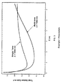
- FIG. 4 is a plot showing the evolution of two laser signals along the direction of propagation (Z) in a 5/10 Er-doped fiber amplifier as per Example 2. For comparison, the case of single tone seeding is plotted.
- FIG. 5 is a plot comparing the total field amplitude Stokes gain for a single tone to that for the multi-tone case of Example 2.
- FIG. 6 is a plot of the evolution of two laser signals along the direction of propagation in a 10/125 Yb-doped fiber amplifier (Example 3) with the case of a single tone seeding plotted for comparison.
- FIG. 7 is a plot showing the reduced Stokes gain due to two-tone seeding for the 10/125 Yb-doped fiber amplifier of Example 3.
- FIG. 9 is a plot showing reduced Stokes gain due to two-tone seeding for a 25/400 Yb-doped fiber amplifier as per Example 4.
- the present invention is a method of reducing the stimulated Brillouin scattering (SBS) effect in order to allow for the design of high power narrow linewidth lasers and amplifiers.
- SBS stimulated Brillouin scattering
- the invention is applicable to various waveguide structures comprised of core and cladding regions in which most of the light power is contained in the core.
- the invention will also work in conjunction with other SBS suppressing schemes.
- a fiber amplifier consists of a silica core doped with a rare earth element most notably erbium (Er), ytterbium (Yb), or thulium (TM).
- a rare earth element most notably erbium (Er), ytterbium (Yb), or thulium (TM).
- the purpose of the rare earth dopant is to provide laser gain.
- the core is also injected with other dopants for other purposes.
- germanium is used to raise the effective index of refraction of the core and allow guiding via total internal reflection.
- laser gain is achieved when a sufficient number of electrons are made to occupy the upper energy lasing level of a rare earth ion. This process is known as population inversion and can be achieved by injecting what is known in the art as pump light into the fiber.
- This process is typically facilitated by designing double clad fibers which allow significant portion of pump light to propagate in the inner cladding before being absorbed in the core.
- a laser beam called the “signal” is coupled into the core.
- This signal travels along the length of the fiber, it sees laser gain due to the population inversion and is amplified.
- power is typically transferred from the low brightness multi-mode pump light and into the high brightness single mode light making the amplifier suitable for a variety of applications.
- SBS can limit this process and will thus impose an upper limit (threshold) on the amount of signal light that can be generated in a given amplifier.
- the present invention makes use of the simultaneous illumination of the fiber amplifier by two or more seed signals possessing different frequencies in order to raise the power output of one of the signals to levels well beyond what the maximum output would have been had the amplifier been illuminated with just a single frequency beam.
- FIG. 1 illustrates one possible experimental implementation of the invention.
- Two master oscillator power amplifiers (MOPAs) are used to generate two beams of seed light 1 , 2 oscillating at different frequencies. This also means that the wavelengths of the two beams will be different.
- the two beams are brought together in an optical combiner 3 before being coupled into the gain fiber 4 whereby amplification of the light signals occurs.
- the gain fiber 4 contains a guiding core that is doped with a rare-earth element.
- the gain fiber is pumped 5 by an array of diode lasers.
- a typical pump wavelength for a Yb-doped amplifier, for example, is in the vicinity of 976 nm.
- the double clad fiber amplifier is spliced onto a cladding mode stripper 9 which will couple out all unused pump light.
- a diagnostic leg is imaged with an optical spectrum analyzer (OSA) 10 to ensure the appropriate power ratio between the two input seed signals.
- OSA optical spectrum analyzer
- the backward-travelling Stokes light is monitored using a 1% backward tap coupler 7 spliced into the fiber and imaged with another OSA.
- optical isolators 8 are employed in the set-up.
- the power ratios among the seed signals are the power ratios among the seed signals and the wavelength (or equivalently frequency) separations.
- the interplay of these parameters was not understood and in fact the scientific literature taught that no power enhancement can be obtained in the output power of any one of the signal lasers.
- the wavelength separation is approximately 10 nm or greater and the ratio of the input seed powers is skewed substantially.
- the skew in the power ratio is such that the signal light that provides the greatest amplifier output has the lowest seed power input.
- the principle objective of this invention is to generate enhanced narrow linewidth power in only one of the tones, the signal light with the highest power input (and therefore lowest power output) need not possess narrow linewidth.
- the use of a broad line width input in one of the signals can lead to better power enhancement of the narrow line width output as will be illustrated in Example (4).
- g 1 and n 1 are the laser gain and the linear index of refraction for the signal seed oscillating at ⁇ 1 , respectively, and where g 2 and n 2 are the laser gain and the linear index of refraction for the signal seed oscillating at ⁇ 2 , respectively.
- the population densities at steady state can be obtained using standard laser physics treatment of quasi-two level systems.
- the total population density is equal to the rare-earth ion density in the material, N 0 .
- the upper level population density is related to the absorption and emission cross sections and the signal and pump waves intensities by:
- N 2 ( ⁇ 1 ( a ) h _ ⁇ ⁇ 1 ⁇ I 1 + ⁇ 2 ( a ) h _ ⁇ ⁇ 2 ⁇ I 2 + ⁇ p ( a ) h _ ⁇ ⁇ p ) ⁇ N 0 ( ⁇ 1 ( a ) + ⁇ 1 ( e ) ) h _ ⁇ ⁇ 1 ⁇ I 1 + ( ⁇ 2 ( a ) + ⁇ 2 ( e ) ) h _ ⁇ ⁇ 2 ⁇ I 2 + ( ⁇ p ( a ) + ⁇ p ( e ) ) h _ ⁇ ⁇ p ⁇ I p + 1 ⁇ ( 6 ) where ⁇ is the lifetime of the upper laser level.
- the evolution of the pump intensity is given by:
- I p d z d core 2 d clad 2 ⁇ ( N 2 ⁇ ⁇ p ( e ) - N 1 ⁇ ⁇ p ( a ) ) ⁇ I p ( 7 )
- d core and d clad are the diameters of the core and cladding regions, respectively.
- the two Stokes waves are initiated from noise and travel in the backward direction.
- Stokes gain is obtained through SBS scattering and laser gain.
- the evolution of the Stokes intensities is given by:
- the emission and absorption cross sections for rare earth-doped silica are different for different frequencies (wavelengths). These cross sections have been extensively studied and their values are well-documented. As an example, for Yb-doped silica the emission and absorption cross sections at 1070 nm are approximately 25% and 60% less than those at 1050 nm light, respectively.
- Equation (3) indicates that occurs when ⁇ 2 (e) N 2 > ⁇ 2 a N 1 .
- the absorption cross section of signal 1 is much smaller than that of signal 2 , the former will continue to experience laser gain leading to a power transfer from both signal 2 and the pump light and into signal 1 .
- the reduction to in the Stokes light is due to the suppressed amplification of signal 1 in a significant portion of the fiber as can be inferred from Equations (8) and (9).
- Example 1 A 6.5 m Yb-doped fiber with a core mode field diameter (MFD) of 25 ⁇ m and an inner cladding MFD of 400 ⁇ m.
- the dopant level in the core is 1.2 ⁇ 10 26 /m 3 .
- the amplifier is seeded with narrow linewidth ( ⁇ 1 MHz) 1050 nm and narrow linewidth ( ⁇ 1 MHz) 1064 nm light beams with a power ratio of 9:1 and total input power of 2 W.
- the pump wavelength is 977 nm. For single seed input, the maximum power output of this amplifier will be approximately 28 W, while for this two-tone case, 46 W of power will be obtained in the 1064 nm light.
- FIG. 2 shows the spatial evolution of the two-tone case and compares it to that of the single tone.
- FIG. 3 illustrates the reduction in the Stokes gain. For comparison purposes, this figure was generated by reducing the pump light for the two-tone case such that the output at 1064 nm was the same as the single-tone case.
- Example 2 A 20 m Er-doped fiber with a core mode field diameter (MFD) of 5 ⁇ m and an inner cladding MFD of 10 ⁇ m.
- the dopant level in the core is 7 ⁇ 10 24 /m 3 .
- the amplifier is seeded with narrow linewidth ( ⁇ 1 MHz)1565 nm and narrow linewidth ( ⁇ 1 MHz) 1575 nm light beams with a power ratio of 4:1 and total input power of 100 mW.
- the pump wavelength is 980 nm.
- the maximum power output of this amplifier will be approximately 0.45 W, while for this two-tone case 0.9 W of power will be obtained in the 1575 nm light.
- FIG. 4 shows the spatial evolution of the two-tone case and compares it to that of the single tone. Note that the power output in the 1575 nm light is doubled.
- FIG. 5 illustrates the reduction in the Stokes gain. For comparison purposes, this figure was generated by reducing the pump light for the two-tone case such that the output at 1575 nm was the same as the single-tone case.
- Example 3 A 6.5 m Yb-doped fiber with a core mode field diameter (MFD) of 10 ⁇ m and an inner cladding MFD of 125 ⁇ m.
- the dopant level in the core is 1.2 ⁇ 10 26 /m 3 .
- the amplifier is seeded with narrow linewidth 1041 nm and narrow linewidth ( ⁇ 1 MHz) 1084 nm light beams with a power ratio of 9:1 and total input power of 0.5 W.
- the pump wavelength is 977 nm.
- the maximum power output of this amplifier will be approximately 6 W.
- approximately 9.5 W of power will be obtained in the 1084 nm light for an enhancement of approximately 60%.
- FIG. 6 shows the spatial evolution of the two-tone case and compares it to that of the single tone.
- FIG. 7 illustrates the reduction in the Stokes gain. For comparison purposes, this figure was generated by reducing the pump light for the two-tone case such that the output at 1084 nm was the same as the single-tone case.
- Example 4 A 6.5 m Yb-doped fiber with a core mode field diameter (MFD) of 25 ⁇ m and an inner cladding MFD of 400 ⁇ m.
- the dopant level in the core is 1.2 ⁇ 10 26 /m 3 .
- the amplifier is seeded with broad line width (approximately 400 MHz) 1041 nm beam at an input power of 5 W and narrow line width ( ⁇ 1 MHz) 1064 nm light beam at an input power of 10 mW.
- the pump wavelength is 977 nm. For single seed input, the maximum power output of this amplifier will be approximately 28 W, while for this two-tone case, 77 W of power will be obtained in the 1064 nm light.
- FIG. 8 shows the spatial evolution of the two-tone case and compares it to that of the single tone.
- FIG. 9 illustrates the reduction in the Stokes gain. For comparison purposes, this figure was generated by reducing the pump light for the two-tone case such that the output at 1064 nm was the same as the single-tone case.
Landscapes
- Physics & Mathematics (AREA)
- Electromagnetism (AREA)
- Engineering & Computer Science (AREA)
- Plasma & Fusion (AREA)
- Optics & Photonics (AREA)
- Lasers (AREA)
Abstract
Description
P th≈21 A eff /g B L eff (1)
where Aeff is the optical effective area, Leff is the effective interaction length, and where gB is the peak value of the Brillouin gain. Therefore, The SBS threshold can be increased by decreasing the effective length of the fiber, increasing the effective area, or somehow manipulating the Brillouin gain in the fiber. The increase in the SBS threshold through the decrease of length is limited by the gain requirements in the fiber. Moreover, increased gain per unit length through the use of higher concentrations of rare earth elements is beset with problems associated with photodarkening and solubility limits. Much work has been done to increase the effective area of the fiber through the use of large mode area (LMA) fibers. While conventional LMA fiber designs have been successful in delivering single mode power outputs exceeding 100 watts, there is general agreement that new approaches are required for further enhancement is of the power.
where g1 and n1 are the laser gain and the linear index of refraction for the signal seed oscillating at ω1, respectively, and where g2 and n2 are the laser gain and the linear index of refraction for the signal seed oscillating at ω2, respectively. The laser gain coefficients for the two frequencies are given by:
g 1 =N 2σ1 (e) −N 1σ1 (a), (4)
g 2 =N 2σ2 (e) −N 1σ2 (a), (5)
where N1 and N2 are the population densities of the upper and lower energy levels, respectively, σ1 (e) and σ1 (a) are the emission and absorption cross sections for ω1, respectively, and where σ2 (e) and σ2 (a) are the emission and absorption cross sections for ω2, respectively. The population densities at steady state can be obtained using standard laser physics treatment of quasi-two level systems. The total population density is equal to the rare-earth ion density in the material, N0. The upper level population density is related to the absorption and emission cross sections and the signal and pump waves intensities by:
where τ is the lifetime of the upper laser level. For a co-propagating pump in a double clad configuration, the evolution of the pump intensity is given by:
Claims (4)
Priority Applications (1)
| Application Number | Priority Date | Filing Date | Title |
|---|---|---|---|
| US12/198,308 US7764720B1 (en) | 2008-08-26 | 2008-08-26 | Multi-tone driven high-power narrow-linewidth rare earth doped fiber amplifier |
Applications Claiming Priority (1)
| Application Number | Priority Date | Filing Date | Title |
|---|---|---|---|
| US12/198,308 US7764720B1 (en) | 2008-08-26 | 2008-08-26 | Multi-tone driven high-power narrow-linewidth rare earth doped fiber amplifier |
Publications (1)
| Publication Number | Publication Date |
|---|---|
| US7764720B1 true US7764720B1 (en) | 2010-07-27 |
Family
ID=42341922
Family Applications (1)
| Application Number | Title | Priority Date | Filing Date |
|---|---|---|---|
| US12/198,308 Expired - Fee Related US7764720B1 (en) | 2008-08-26 | 2008-08-26 | Multi-tone driven high-power narrow-linewidth rare earth doped fiber amplifier |
Country Status (1)
| Country | Link |
|---|---|
| US (1) | US7764720B1 (en) |
Cited By (23)
| Publication number | Priority date | Publication date | Assignee | Title |
|---|---|---|---|---|
| US20100166026A1 (en) * | 2008-12-31 | 2010-07-01 | Ipg Photonics Corporation | High-power narrowed-linewidth fiber laser system |
| US20100260212A1 (en) * | 2009-04-10 | 2010-10-14 | Fujikura Ltd. | Fiber output stabilizer |
| US20110038579A1 (en) * | 2005-10-02 | 2011-02-17 | Elbit Systems Electro-Optics Elop Ltd. | Fiber lasers |
| US20110222574A1 (en) * | 2010-03-09 | 2011-09-15 | Massachusetts Institute Of Technology | Two-dimensional wavelength-beam-combining of lasers using first-order grating stack |
| US20110280581A1 (en) * | 2010-05-12 | 2011-11-17 | Massachusetts Institute Of Technology | Systems and methods for producing high-power laser beams |
| US20110317256A1 (en) * | 2010-06-24 | 2011-12-29 | Cymer, Inc. | Master oscillator-power amplifier drive laser with pre-pulse for euv light source |
| US8462426B1 (en) * | 2009-12-03 | 2013-06-11 | The United States Of America As Represented By The Secretary Of The Air Force | Scalable monolithic single frequency fiber amplifier |
| US8531761B2 (en) | 2010-05-27 | 2013-09-10 | Massachusetts Institute Of Technology | High peak power optical amplifier |
| US8531772B2 (en) | 2008-11-04 | 2013-09-10 | Massachusetts Institute Of Technology | External-cavity one-dimensional multi-wavelength beam combining of two-dimensional laser elements |
| CN103490272A (en) * | 2013-09-11 | 2014-01-01 | 上海交通大学 | 2um single frequency pulse fiber laser adjustable in amplitude modulation frequency |
| US8761210B1 (en) * | 2011-08-17 | 2014-06-24 | The United States Of America As Represented By The Secretary Of The Air Force | Generating narrow linewidth 1178 NM laser output using a seeded raman amplifier |
| US20150236789A1 (en) * | 2014-01-24 | 2015-08-20 | Kerry VAHALA | Dual-frequency optical source |
| US9515451B2 (en) | 2015-01-29 | 2016-12-06 | Massachusetts Institute Of Technology | Systems and methods for light amplification |
| US20170063019A1 (en) * | 2014-04-30 | 2017-03-02 | Gwangju Institute Of Science And Technology | Optical fiber laser device and optical fiber laser providing method |
| US9620928B2 (en) | 2010-07-16 | 2017-04-11 | Massachusetts Institute Of Technology | Continuous wave or ultrafast lasers |
| US9905999B2 (en) | 2015-02-26 | 2018-02-27 | California Institute Of Technology | Optical frequency divider based on an electro-optical-modulator frequency comb |
| WO2018047867A1 (en) * | 2016-09-09 | 2018-03-15 | 住友電気工業株式会社 | Optical amplifier and multi-core optical fiber |
| CN108462024A (en) * | 2018-05-29 | 2018-08-28 | 中国人民解放军国防科技大学 | System for inhibiting unstable thermally induced mode in high-brightness narrow-linewidth ytterbium-doped optical fiber amplifier |
| US20180366897A1 (en) * | 2018-07-09 | 2018-12-20 | University Of Electronic Science And Technology Of China | Random distributed Rayleigh feedback fiber laser based on double-cladding weakly ytterbium-doped fiber |
| CN111541138A (en) * | 2020-04-17 | 2020-08-14 | 华南理工大学 | Device for inhibiting stimulated Brillouin scattering in high-power narrow-linewidth optical fiber laser |
| WO2020188232A1 (en) * | 2019-03-15 | 2020-09-24 | Spi Lasers Uk Limited | Apparatus for providing optical radiation |
| US20220239055A1 (en) * | 2021-01-25 | 2022-07-28 | Applied Energetics, Inc. | Multiple coherent wavelength optical sources |
| CN115313131A (en) * | 2022-09-02 | 2022-11-08 | 杭州奥创光子技术有限公司 | Pulse laser device for inhibiting stimulated Brillouin scattering |
-
2008
- 2008-08-26 US US12/198,308 patent/US7764720B1/en not_active Expired - Fee Related
Non-Patent Citations (2)
| Title |
|---|
| E. Lichtman et al, "Stimulated Brillouin scattering excited by two pump waves in single-mode fibers", J. Optical Soc. of America, pp. 1397-1403, vol. 4 No. 9 Sep. 1987. |
| P. Wessels et al, "Novel suppression scheme for Brillouin scattering", Optics Express 12, pp. 4443-4448, Sep. 20, 2004. |
Cited By (42)
| Publication number | Priority date | Publication date | Assignee | Title |
|---|---|---|---|---|
| US20110038579A1 (en) * | 2005-10-02 | 2011-02-17 | Elbit Systems Electro-Optics Elop Ltd. | Fiber lasers |
| US8768118B2 (en) * | 2005-10-02 | 2014-07-01 | Elbit Systems Electro-Optics Elop Ltd. | Fiber lasers |
| US8531772B2 (en) | 2008-11-04 | 2013-09-10 | Massachusetts Institute Of Technology | External-cavity one-dimensional multi-wavelength beam combining of two-dimensional laser elements |
| US7903696B2 (en) * | 2008-12-31 | 2011-03-08 | Ipg Photonics Corporation | High-power narrowed-linewidth fiber laser system |
| US20100166026A1 (en) * | 2008-12-31 | 2010-07-01 | Ipg Photonics Corporation | High-power narrowed-linewidth fiber laser system |
| US20100260212A1 (en) * | 2009-04-10 | 2010-10-14 | Fujikura Ltd. | Fiber output stabilizer |
| US8422890B2 (en) * | 2009-04-10 | 2013-04-16 | Fujikura Ltd. | Fiber output stabilizer |
| US8462426B1 (en) * | 2009-12-03 | 2013-06-11 | The United States Of America As Represented By The Secretary Of The Air Force | Scalable monolithic single frequency fiber amplifier |
| US20110222574A1 (en) * | 2010-03-09 | 2011-09-15 | Massachusetts Institute Of Technology | Two-dimensional wavelength-beam-combining of lasers using first-order grating stack |
| US8614853B2 (en) | 2010-03-09 | 2013-12-24 | Massachusetts Institute Of Technology | Two-dimensional wavelength-beam-combining of lasers using first-order grating stack |
| US9575325B2 (en) | 2010-03-09 | 2017-02-21 | Massachusetts Institute Of Technology | Two-dimensional wavelength-beam-combining of lasers using first-order grating stack |
| US20110280581A1 (en) * | 2010-05-12 | 2011-11-17 | Massachusetts Institute Of Technology | Systems and methods for producing high-power laser beams |
| US8531761B2 (en) | 2010-05-27 | 2013-09-10 | Massachusetts Institute Of Technology | High peak power optical amplifier |
| US9136667B2 (en) | 2010-05-27 | 2015-09-15 | Massachusetts Institute Of Technology | High peak power optical amplifier |
| US20110317256A1 (en) * | 2010-06-24 | 2011-12-29 | Cymer, Inc. | Master oscillator-power amplifier drive laser with pre-pulse for euv light source |
| US8654438B2 (en) * | 2010-06-24 | 2014-02-18 | Cymer, Llc | Master oscillator-power amplifier drive laser with pre-pulse for EUV light source |
| US9620928B2 (en) | 2010-07-16 | 2017-04-11 | Massachusetts Institute Of Technology | Continuous wave or ultrafast lasers |
| US9293889B1 (en) * | 2011-08-17 | 2016-03-22 | The United States Of America As Represented By The Secretary Of The Air Force | Seeded Raman amplifier in a nested configuration for generating a 1240 nm laser |
| US9054499B1 (en) * | 2011-08-17 | 2015-06-09 | The United States Of America As Represented By The Secretary Of The Air Force | Seeded Raman amplifier in linear configuration for laser applications in the 1100-1500 nm spectral range |
| US8761210B1 (en) * | 2011-08-17 | 2014-06-24 | The United States Of America As Represented By The Secretary Of The Air Force | Generating narrow linewidth 1178 NM laser output using a seeded raman amplifier |
| CN103490272B (en) * | 2013-09-11 | 2015-11-18 | 上海交通大学 | Amplitude modified frequency is adjustable 2um SF pulse optical fibre laser |
| CN103490272A (en) * | 2013-09-11 | 2014-01-01 | 上海交通大学 | 2um single frequency pulse fiber laser adjustable in amplitude modulation frequency |
| US20150236789A1 (en) * | 2014-01-24 | 2015-08-20 | Kerry VAHALA | Dual-frequency optical source |
| US9537571B2 (en) * | 2014-01-24 | 2017-01-03 | California Institute Of Technology | Dual-frequency optical source |
| US10009103B2 (en) | 2014-01-24 | 2018-06-26 | California Institute Of Technology | Stabilized microwave-frequency source |
| US9979153B2 (en) * | 2014-04-30 | 2018-05-22 | Gwangju Institute Of Science And Technology | Optical fiber laser device and optical fiber laser providing method |
| US20170063019A1 (en) * | 2014-04-30 | 2017-03-02 | Gwangju Institute Of Science And Technology | Optical fiber laser device and optical fiber laser providing method |
| US9515451B2 (en) | 2015-01-29 | 2016-12-06 | Massachusetts Institute Of Technology | Systems and methods for light amplification |
| US9905999B2 (en) | 2015-02-26 | 2018-02-27 | California Institute Of Technology | Optical frequency divider based on an electro-optical-modulator frequency comb |
| WO2018047867A1 (en) * | 2016-09-09 | 2018-03-15 | 住友電気工業株式会社 | Optical amplifier and multi-core optical fiber |
| JPWO2018047867A1 (en) * | 2016-09-09 | 2019-06-27 | 住友電気工業株式会社 | Optical amplifier and multi-core optical fiber |
| CN108462024A (en) * | 2018-05-29 | 2018-08-28 | 中国人民解放军国防科技大学 | System for inhibiting unstable thermally induced mode in high-brightness narrow-linewidth ytterbium-doped optical fiber amplifier |
| CN108462024B (en) * | 2018-05-29 | 2023-09-22 | 中国人民解放军国防科技大学 | System for inhibiting thermal induced mode instability in high-brightness narrow-linewidth ytterbium-doped optical fiber amplifier |
| US20180366897A1 (en) * | 2018-07-09 | 2018-12-20 | University Of Electronic Science And Technology Of China | Random distributed Rayleigh feedback fiber laser based on double-cladding weakly ytterbium-doped fiber |
| US10644475B2 (en) * | 2018-07-09 | 2020-05-05 | University Of Electronic Science And Technology Of China | Random distributed Rayleigh feedback fiber laser based on double-cladding weakly ytterbium-doped fiber |
| WO2020188232A1 (en) * | 2019-03-15 | 2020-09-24 | Spi Lasers Uk Limited | Apparatus for providing optical radiation |
| US12548969B2 (en) | 2019-03-15 | 2026-02-10 | Trumpf Laser Uk Limited | Optical amplifier with two seed source lasers controlled to reduce stimulated Brillouin scattering |
| CN111541138A (en) * | 2020-04-17 | 2020-08-14 | 华南理工大学 | Device for inhibiting stimulated Brillouin scattering in high-power narrow-linewidth optical fiber laser |
| CN111541138B (en) * | 2020-04-17 | 2021-11-19 | 华南理工大学 | Device for inhibiting stimulated Brillouin scattering in high-power narrow-linewidth optical fiber laser |
| US20220239055A1 (en) * | 2021-01-25 | 2022-07-28 | Applied Energetics, Inc. | Multiple coherent wavelength optical sources |
| US12413039B2 (en) * | 2021-01-25 | 2025-09-09 | Applied Energetics, Inc. | Multiple coherent wavelength optical sources |
| CN115313131A (en) * | 2022-09-02 | 2022-11-08 | 杭州奥创光子技术有限公司 | Pulse laser device for inhibiting stimulated Brillouin scattering |
Similar Documents
| Publication | Publication Date | Title |
|---|---|---|
| US7764720B1 (en) | Multi-tone driven high-power narrow-linewidth rare earth doped fiber amplifier | |
| US8462426B1 (en) | Scalable monolithic single frequency fiber amplifier | |
| EP1564853B1 (en) | Fiber amplifier for generating femtosecond pulses in single mode fiber | |
| US9246296B2 (en) | Laser or amplifier optical device seeded with nonlinearly generated light | |
| JP3325887B2 (en) | Optical waveguide amplifier | |
| KR102008377B1 (en) | High power single mode ytterbium fiber laser system with signle mode neodymium fiber source | |
| US7477667B2 (en) | Practical approach for one mJ femtosecond fiber laser | |
| US20080304137A1 (en) | Light source apparatus | |
| US9979153B2 (en) | Optical fiber laser device and optical fiber laser providing method | |
| GB2340989A (en) | Optical fibre amplifier | |
| US20190140416A1 (en) | Cladding-Pumped Hybrid Amplification Structure And Method | |
| CA2693112A1 (en) | Fiber laser having superior resistance to reflection light | |
| US7822314B1 (en) | Segmented acoustic core photonic crystal fiber laser | |
| CN117220127B (en) | A fiber laser that suppresses stimulated Raman scattering and its parameter optimization method | |
| Yu et al. | High-power, low noise, high gain few-mode fiber amplifier | |
| Walasik et al. | 1760 nm multi-watt broadband pm cw and pulsed tm-doped fiber amplifier | |
| US6363087B1 (en) | Multimode raman fiber amplifier and method | |
| US20140286362A1 (en) | High Power Neodymium Fiber Lasers and Amplifiers | |
| Luo et al. | High-brightness 980 nm all-fiber oscillator with 27% slope efficiency using chirped and tilted fiber Bragg grating | |
| Romano et al. | Ultra-flat supercontinuum from 1.95 to 2.65 µm in a nanosecond pulsed Thulium-doped fiber laser | |
| Zhu et al. | A high flattening C+ L band broadband source based on single pump and the same erbium-doped fiber | |
| Zhang et al. | Triple-clad-fiber-based kilowatt-level tunable Raman laser | |
| Zhang et al. | Flat supercontinuum generation covering C-band to U-band in two-stage Er/Yb co-doped double-clad fiber amplifier | |
| Romano et al. | 5 W 1952 nm Brillouin-free efficient single clad TDFA | |
| JP2007005484A (en) | Optical amplifier and optical fiber |
Legal Events
| Date | Code | Title | Description |
|---|---|---|---|
| AS | Assignment |
Owner name: THE GOVERNMENT OF THE UNITED STATES AS REPRESENTED Free format text: ASSIGNMENT OF ASSIGNORS INTEREST;ASSIGNORS:DAJANI, IYAD A.;ZERINGUE, CLINT M.;SHAY, THOMAS M.;AND OTHERS;SIGNING DATES FROM 20080825 TO 20080826;REEL/FRAME:021442/0044 |
|
| STCF | Information on status: patent grant |
Free format text: PATENTED CASE |
|
| FPAY | Fee payment |
Year of fee payment: 4 |
|
| CC | Certificate of correction | ||
| FEPP | Fee payment procedure |
Free format text: MAINTENANCE FEE REMINDER MAILED (ORIGINAL EVENT CODE: REM.) |
|
| FEPP | Fee payment procedure |
Free format text: 7.5 YR SURCHARGE - LATE PMT W/IN 6 MO, LARGE ENTITY (ORIGINAL EVENT CODE: M1555) |
|
| MAFP | Maintenance fee payment |
Free format text: PAYMENT OF MAINTENANCE FEE, 8TH YEAR, LARGE ENTITY (ORIGINAL EVENT CODE: M1552) Year of fee payment: 8 |
|
| FEPP | Fee payment procedure |
Free format text: MAINTENANCE FEE REMINDER MAILED (ORIGINAL EVENT CODE: REM.); ENTITY STATUS OF PATENT OWNER: LARGE ENTITY |
|
| LAPS | Lapse for failure to pay maintenance fees |
Free format text: PATENT EXPIRED FOR FAILURE TO PAY MAINTENANCE FEES (ORIGINAL EVENT CODE: EXP.); ENTITY STATUS OF PATENT OWNER: LARGE ENTITY |
|
| STCH | Information on status: patent discontinuation |
Free format text: PATENT EXPIRED DUE TO NONPAYMENT OF MAINTENANCE FEES UNDER 37 CFR 1.362 |
|
| FP | Lapsed due to failure to pay maintenance fee |
Effective date: 20220727 |