US7762142B2 - Integrated fastener-sensor arrangement - Google Patents
Integrated fastener-sensor arrangement Download PDFInfo
- Publication number
- US7762142B2 US7762142B2 US12/205,534 US20553408A US7762142B2 US 7762142 B2 US7762142 B2 US 7762142B2 US 20553408 A US20553408 A US 20553408A US 7762142 B2 US7762142 B2 US 7762142B2
- Authority
- US
- United States
- Prior art keywords
- fastener
- layer structure
- active
- sensor circuit
- passive
- Prior art date
- Legal status (The legal status is an assumption and is not a legal conclusion. Google has not performed a legal analysis and makes no representation as to the accuracy of the status listed.)
- Active, expires
Links
- 230000004044 response Effects 0.000 claims abstract description 63
- 238000011065 in-situ storage Methods 0.000 claims abstract description 10
- 239000010410 layer Substances 0.000 claims description 167
- 239000004020 conductor Substances 0.000 claims description 47
- 238000000034 method Methods 0.000 claims description 25
- 239000000463 material Substances 0.000 claims description 24
- 230000007797 corrosion Effects 0.000 claims description 11
- 238000005260 corrosion Methods 0.000 claims description 11
- 238000001514 detection method Methods 0.000 claims description 9
- 238000004804 winding Methods 0.000 claims description 8
- 230000008569 process Effects 0.000 claims description 6
- 238000000926 separation method Methods 0.000 claims description 6
- 230000005684 electric field Effects 0.000 claims description 4
- 230000001939 inductive effect Effects 0.000 claims description 4
- 238000003780 insertion Methods 0.000 claims description 2
- 230000037431 insertion Effects 0.000 claims description 2
- 230000008878 coupling Effects 0.000 claims 1
- 238000010168 coupling process Methods 0.000 claims 1
- 238000005859 coupling reaction Methods 0.000 claims 1
- 238000000151 deposition Methods 0.000 claims 1
- 239000002344 surface layer Substances 0.000 claims 1
- 238000013459 approach Methods 0.000 description 29
- 230000005284 excitation Effects 0.000 description 16
- 238000012360 testing method Methods 0.000 description 15
- 230000001965 increasing effect Effects 0.000 description 14
- 238000013461 design Methods 0.000 description 12
- 239000002356 single layer Substances 0.000 description 12
- 238000005259 measurement Methods 0.000 description 11
- 239000007858 starting material Substances 0.000 description 11
- 230000006870 function Effects 0.000 description 10
- 239000000654 additive Substances 0.000 description 9
- 230000000996 additive effect Effects 0.000 description 9
- 206010016256 fatigue Diseases 0.000 description 9
- 230000036541 health Effects 0.000 description 9
- 238000012544 monitoring process Methods 0.000 description 8
- RYGMFSIKBFXOCR-UHFFFAOYSA-N Copper Chemical compound [Cu] RYGMFSIKBFXOCR-UHFFFAOYSA-N 0.000 description 7
- 239000010949 copper Substances 0.000 description 7
- 229910052802 copper Inorganic materials 0.000 description 7
- 238000007689 inspection Methods 0.000 description 7
- 230000005291 magnetic effect Effects 0.000 description 7
- 239000007921 spray Substances 0.000 description 7
- PNEYBMLMFCGWSK-UHFFFAOYSA-N aluminium oxide Inorganic materials [O-2].[O-2].[O-2].[Al+3].[Al+3] PNEYBMLMFCGWSK-UHFFFAOYSA-N 0.000 description 5
- 238000000576 coating method Methods 0.000 description 5
- 238000009434 installation Methods 0.000 description 5
- XKRFYHLGVUSROY-UHFFFAOYSA-N Argon Chemical compound [Ar] XKRFYHLGVUSROY-UHFFFAOYSA-N 0.000 description 4
- GWEVSGVZZGPLCZ-UHFFFAOYSA-N Titan oxide Chemical compound O=[Ti]=O GWEVSGVZZGPLCZ-UHFFFAOYSA-N 0.000 description 4
- 229910052782 aluminium Inorganic materials 0.000 description 4
- XAGFODPZIPBFFR-UHFFFAOYSA-N aluminium Chemical group [Al] XAGFODPZIPBFFR-UHFFFAOYSA-N 0.000 description 4
- 239000011248 coating agent Substances 0.000 description 4
- 230000001066 destructive effect Effects 0.000 description 4
- 230000000694 effects Effects 0.000 description 4
- 230000003993 interaction Effects 0.000 description 4
- 229910052751 metal Inorganic materials 0.000 description 4
- 238000004458 analytical method Methods 0.000 description 3
- 238000000608 laser ablation Methods 0.000 description 3
- 239000002184 metal Substances 0.000 description 3
- 238000012986 modification Methods 0.000 description 3
- 230000004048 modification Effects 0.000 description 3
- 230000035945 sensitivity Effects 0.000 description 3
- 239000000758 substrate Substances 0.000 description 3
- 208000027418 Wounds and injury Diseases 0.000 description 2
- 229910052786 argon Inorganic materials 0.000 description 2
- 229910052799 carbon Inorganic materials 0.000 description 2
- 238000006073 displacement reaction Methods 0.000 description 2
- 230000000977 initiatory effect Effects 0.000 description 2
- 230000010354 integration Effects 0.000 description 2
- 230000037231 joint health Effects 0.000 description 2
- 230000003287 optical effect Effects 0.000 description 2
- 230000001151 other effect Effects 0.000 description 2
- 230000035515 penetration Effects 0.000 description 2
- 239000000523 sample Substances 0.000 description 2
- 239000004065 semiconductor Substances 0.000 description 2
- 125000006850 spacer group Chemical group 0.000 description 2
- 239000000126 substance Substances 0.000 description 2
- 238000010200 validation analysis Methods 0.000 description 2
- 229910000838 Al alloy Inorganic materials 0.000 description 1
- 230000005355 Hall effect Effects 0.000 description 1
- XOJVVFBFDXDTEG-UHFFFAOYSA-N Norphytane Natural products CC(C)CCCC(C)CCCC(C)CCCC(C)C XOJVVFBFDXDTEG-UHFFFAOYSA-N 0.000 description 1
- RTAQQCXQSZGOHL-UHFFFAOYSA-N Titanium Chemical compound [Ti] RTAQQCXQSZGOHL-UHFFFAOYSA-N 0.000 description 1
- ILROEEPCXNSJHI-UHFFFAOYSA-N [Ne].[In] Chemical compound [Ne].[In] ILROEEPCXNSJHI-UHFFFAOYSA-N 0.000 description 1
- 239000000853 adhesive Substances 0.000 description 1
- 230000001070 adhesive effect Effects 0.000 description 1
- 229910045601 alloy Inorganic materials 0.000 description 1
- 239000000956 alloy Substances 0.000 description 1
- 238000003491 array Methods 0.000 description 1
- 230000008901 benefit Effects 0.000 description 1
- 239000000919 ceramic Substances 0.000 description 1
- 230000008859 change Effects 0.000 description 1
- 238000002485 combustion reaction Methods 0.000 description 1
- 238000004891 communication Methods 0.000 description 1
- 229920001940 conductive polymer Polymers 0.000 description 1
- MPTQRFCYZCXJFQ-UHFFFAOYSA-L copper(II) chloride dihydrate Chemical compound O.O.[Cl-].[Cl-].[Cu+2] MPTQRFCYZCXJFQ-UHFFFAOYSA-L 0.000 description 1
- 229910052593 corundum Inorganic materials 0.000 description 1
- 238000005336 cracking Methods 0.000 description 1
- 238000003745 diagnosis Methods 0.000 description 1
- 230000003292 diminished effect Effects 0.000 description 1
- 230000002708 enhancing effect Effects 0.000 description 1
- 238000002474 experimental method Methods 0.000 description 1
- 239000011261 inert gas Substances 0.000 description 1
- 238000011900 installation process Methods 0.000 description 1
- 238000003698 laser cutting Methods 0.000 description 1
- 230000007774 longterm Effects 0.000 description 1
- 230000007246 mechanism Effects 0.000 description 1
- 239000007769 metal material Substances 0.000 description 1
- 238000001465 metallisation Methods 0.000 description 1
- 150000002739 metals Chemical class 0.000 description 1
- 239000000203 mixture Substances 0.000 description 1
- 235000012771 pancakes Nutrition 0.000 description 1
- 230000035699 permeability Effects 0.000 description 1
- 230000000704 physical effect Effects 0.000 description 1
- 239000000843 powder Substances 0.000 description 1
- 238000012545 processing Methods 0.000 description 1
- 230000000644 propagated effect Effects 0.000 description 1
- 230000005855 radiation Effects 0.000 description 1
- 238000005070 sampling Methods 0.000 description 1
- 238000001228 spectrum Methods 0.000 description 1
- 238000005507 spraying Methods 0.000 description 1
- 230000003068 static effect Effects 0.000 description 1
- 238000004154 testing of material Methods 0.000 description 1
- 239000010936 titanium Substances 0.000 description 1
- 229910052719 titanium Inorganic materials 0.000 description 1
- 238000012546 transfer Methods 0.000 description 1
- 238000013519 translation Methods 0.000 description 1
- 229910001845 yogo sapphire Inorganic materials 0.000 description 1
Images


Classifications
-
- F—MECHANICAL ENGINEERING; LIGHTING; HEATING; WEAPONS; BLASTING
- F16—ENGINEERING ELEMENTS AND UNITS; GENERAL MEASURES FOR PRODUCING AND MAINTAINING EFFECTIVE FUNCTIONING OF MACHINES OR INSTALLATIONS; THERMAL INSULATION IN GENERAL
- F16B—DEVICES FOR FASTENING OR SECURING CONSTRUCTIONAL ELEMENTS OR MACHINE PARTS TOGETHER, e.g. NAILS, BOLTS, CIRCLIPS, CLAMPS, CLIPS OR WEDGES; JOINTS OR JOINTING
- F16B33/00—Features common to bolt and nut
- F16B33/06—Surface treatment of parts furnished with screw-thread, e.g. for preventing seizure or fretting
-
- G—PHYSICS
- G07—CHECKING-DEVICES
- G07C—TIME OR ATTENDANCE REGISTERS; REGISTERING OR INDICATING THE WORKING OF MACHINES; GENERATING RANDOM NUMBERS; VOTING OR LOTTERY APPARATUS; ARRANGEMENTS, SYSTEMS OR APPARATUS FOR CHECKING NOT PROVIDED FOR ELSEWHERE
- G07C5/00—Registering or indicating the working of vehicles
- G07C5/08—Registering or indicating performance data other than driving, working, idle, or waiting time, with or without registering driving, working, idle or waiting time
- G07C5/0841—Registering performance data
- G07C5/085—Registering performance data using electronic data carriers
Definitions
- the present invention relates generally to sensor applications, and to sensing structural characteristics such as those in areas adjacent or proximate to a fastener.
- Various aspects of the present invention are directed to devices, methods and systems for detecting structural and/or electrical characteristics of multi-layer structures in a manner that addresses challenges including those discussed above.
- an integrated in-situ sensor device senses characteristics of a multi-layer structure during operation thereof.
- the device includes a mechanical coupler and a sensor circuit.
- the mechanical coupler couples layers of the multi-layer structure together via an opening traversing the multi-layer structure.
- the sensor circuit inserts into the opening with the mechanical coupler, induces an electrical response in a portion of the multi-layer structure adjacent the opening, and senses the induced electrical response.
- the electrical response is indicative of characteristics of the multi-layer structure, and a signal is provided from the sensed response to characterize the multi-layer structure.
- a method for sensing characteristics of a multi-layer structure during operation thereof is as follows. Layers of the multi-layer structure are coupled together by inserting a fastener into an opening traversing the multi-layer structure.
- a sensor circuit is inserted into the opening with the fastener, and is used for inducing an electrical response in a portion of the multi-layer structure adjacent the opening, the electrical response being indicative of characteristics of the multi-layer structure, and for sensing the induced electrical response and providing a signal characterizing characteristics of the multi-layer structure.
- a method for detecting the force provided by a fastener during and/or after the installation of a fastener into a structure is as follows. Layers of a multi-layer structure are coupled together by inserting a fastener into an opening transversing the multi-layer structure. A sensor circuit is inserted into the opening with the fastener. During the installation process and/or at any desired point after the installation is complete, the electrical response of the circuit is measured to determine the fastening force provided by the fastener.
- a method for detecting damage to a fastener is as follows. Layers of a multi-layer structure are coupled together by inserting a fastener into an opening transversing the multi-layer structure. A sensor circuit is inserted into the opening with the fastener and is used for inducing an electrical response in a portion of the fastener adjacent the sensor, the electrical response being indicative of characteristics of the fastener, and for sensing the induced electrical response and providing a signal characterizing characteristics of the fastener.
- a corrosion detection arrangement detects a degree of corrosion in a battery.
- the arrangement includes an active electrical conductor to induce an electrical response by a target portion within the battery, and a passive electrical conductor to sense the induced electrical response from the target portion of the battery.
- a controller is coupled to control the active electrical conductor for applying the electric field.
- a processor is coupled to receive a signal corresponding to the induced electrical response from the passive electrical conductor and to process the signal for detecting a characteristic of the target portion of the battery.
- FIG. 1 shows a cross-section of a wing attachment fitting with an integrated fastener-sensor, according to an example embodiment of the present invention
- FIG. 2 shows a system for structural health monitoring, according to another example embodiment of the present invention
- FIG. 3 shows example coil geometries, according to another example embodiment of the present invention.
- FIG. 4 shows interleaved active and passive coil geometries, according to another example embodiment of the present invention.
- FIG. 5 shows excitation coils, according to another example embodiment of the present invention.
- FIG. 6 shows a plot for sensing structural characteristics, according to another example embodiment of the present invention.
- FIG. 8 shows a sensor coil and flaw interaction, according to another example embodiment of the present invention.
- FIG. 9 shows example detection of flaws via eddy current density, according to another example embodiment of the present invention.
- FIG. 10 shows a plot of total current versus flaw depth, according to another example embodiment of the present invention.
- FIG. 11 shows a sensor film with example bonding to a sleeve, according to another example embodiment of the present invention.
- FIG. 12 shows a structural health monitoring system, according to another example embodiment of the present invention.
- FIG. 13 shows a data acquisition system, according to another example embodiment of the present invention.
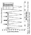
- FIG. 15 shows a plot of sensor power versus time, according to another example embodiment of the present invention.
- FIG. 16 shows another plot of sensor power versus time, according to another example embodiment of the present invention.
- FIG. 17 shows a plot of damage index and flaw depth, according to another example embodiment of the present invention.
- FIG. 18 shows approaches for crack detection, according to another example embodiment of the present invention.
- FIG. 19 shows a plot of sensor power versus time, according to another example embodiment of the present invention.
- FIG. 20 shows a plot of damage index and crack depth, according to another example embodiment of the present invention.
- FIG. 21 shows an approach to detecting characteristics of a specimen, according to another example embodiment of the present invention.
- FIG. 22 shows an approach to detecting characteristics of a specimen, according to another example embodiment of the present invention.
- FIG. 23 shows a plot of damage versus cycles, according to another example embodiment of the present invention.
- FIG. 24 shows another plot of damage versus cycles, according to another example embodiment of the present invention.
- FIG. 25 shows an approach to detecting characteristics of a structure, according to another example embodiment of the present invention.
- FIG. 26 shows a plot of sensor response and loading, according to another example embodiment of the present invention.
- FIG. 27 shows a plot of damage versus cycles, according to another example embodiment of the present invention.
- FIG. 28 shows a plot of damage versus cycles, according to another example embodiment of the present invention.
- FIG. 29 shows an approach to detecting characteristics of a structure, according to another example embodiment of the present invention.
- FIG. 30 shows a plot of damage versus cycles, according to another example embodiment of the present invention.
- FIG. 32 shows an approach to forming an integrated fastener-sensor arrangement, according to another example embodiment of the present invention.
- FIG. 33 shows another approach to forming an integrated fastener-sensor arrangement, according to another example embodiment of the present invention.
- the present invention relates to devices, methods and systems for detecting structural and/or electrical characteristics. While the present invention is not necessarily limited to such approaches, various aspects of the invention may be appreciated through a discussion of examples using these and other contexts.
- a sensor arrangement is implemented in connection with a fastener connected to a structure in order to test or otherwise analyze portions of the structure adjacent to the fastener.
- a fastener connected to a structure in order to test or otherwise analyze portions of the structure adjacent to the fastener.
- Such an approach is useful, for example, to analyze portions of a multi-layer structure that are below or under exposed surfaces and adjacent to fastener locations, such as fasteners used at airplane wing components that are bolted or otherwise fastened together.
- the sensor arrangement induces a response from the structure, detects the response and provides a signal corresponding to the detected response in order to detect characteristics of the structure. Detected characteristics may involve one or more of structural, electrical, corrosion and/or cracking characteristics of the structure.
- a structural health monitoring fastener includes a conformable eddy current sensor film that is integrated with a metallic sleeve that goes around a fastener shank for in-situ monitoring of fatigue cracks at hole locations in layered joints of including conductive material (e.g., metal or semiconducting material).
- Sensors are integrated with the fastener shank to embed the sensors for detecting cracks in airframes, which most commonly initiate at bolt-hole boundaries in metallic components.
- the sensors are located in close proximity to the bolt-hole boundary through the entire joint stack-up, enabling detection of cracks on inner joint layers, which are otherwise inaccessible and cannot be detected by non-destructive inspection equipment without disassembling vehicle components.
- AIME additive, interleaved, multi-layer, electromagnetic
- the sensor system can be permanently integrated with a joint to monitor cracks forming on any layer within the joint stack up, without requiring modification of the joint layers for the purpose of embedding the sensors.
- sensors integrated on the fastener shank facilitate inspection of the fastener both during installation of the fastener into the structure and during the service lifetime of the fastener.
- the resistivity of a single sensor conductor, integrated on the fastener shank is measured for a characteristic directly related to the tension in the fastener. This resistivity is then measured during inspection processes throughout the lifetime of the joint to detect fastener loosening.
- conductors integrated on the fastener shank are used to induce electrical currents in the underlying fastener, and the response of the fastener to those currents is sensed to detect any damage in the form of cracks (e.g., fatigue cracks) and/or corrosion of the fastener.
- an additive, interleaved, multi-layer electromagnetic (AIME) sensor is a conformable eddy current film sensor that has been refined to enhance the capability to inspect adjacent joint layers with liftoff and to track cracks to great depths from the thru-hole boundary.
- Eddy current devices amenable to use with the present invention are described, for example, in references 7-10 cited in the references section below. These references present different example approaches for implementing excitation coils in connection with various example embodiments, such as for a circular or pancake coil, a meandering excitation system, and a planar rectangular coil.
- sensor arrangements implemented herein are manufactured and/or implemented to set induced eddy current direction, facilitate enhanced sensitivity, provide for inspection without contact between sensor and joint layer (with sensor liftoff), and tracking of flaws to increasing depths from bolt-hole boundaries.
- FIG. 3 shows some potential excitation (or active) coil geometries 310 , 320 and 330 , including circular, planar rectangular and meandering coil designs.
- active coil geometries 310 , 320 and 330 including circular, planar rectangular and meandering coil designs.
- the currents produced by the coil flow perpendicular to the axis of the fastener since the eddy current response is highest for cracks that are forming perpendicular to the current direction.
- various discussion herein is based upon the planar rectangular and meandering designs by way of example.
- one embodiments involves using a coil laid out on two layers, with the coils wound such that the current is additive on both layers and in all legs of the coil. Since the winding of the planar coil demands a second layer in order to runout the coil trace once it reaches the inside of the layout, introduction of an additional layer of coil winding may be inconsequential for the final film thickness. This produces a high number of turns for an increased magnetic field strength and improved signal to noise ratio.
- non-destructive inspection is carried out with such coils as eddy current devices, by measuring the electrical impedance of a single active coil and relating impedance changes to the presence of flaws.
- Such approaches may involve, for example, those similar to approaches described in references 11 and 12 cited at the end of this detailed description section.
- a two-coil approach wherein a second, passive coil is used in addition to an excitation coil to facilitate desirable sensitivity and signal to noise ratio.
- the induced voltage on this second passive coil can be measured and responds to the magnitude of the total magnetic field around the active coil, which is a function of the eddy currents and their response to cracks in a material under test (joint layer).
- the strength of the induced field from the active coil is a function of the number of additive turns within this coil.
- the magnitude of the induced voltage on the passive coil is a function of the number of additive turns in this coil according to Faraday's Law. Increasing both the field strength from the active coil and magnitude of the induced voltage on the passive coil leads to a higher signal to noise ratio for the sensor.
- FIG. 4 shows two layers with planar coils on each layer that are wound such that the current is additive in the legs of the coil. Interleaved within the active coil is a passive coil, used to detect changes in the induced field from the excitation coil and eddy currents in the joint layer.
- This approach thus involves an additive, interleaved, multi-layer, electro-magnetic sensor, or AIME sensor.
- An example related sensor film is shown in FIG. 11 (left).
- a sensor arrangement is implemented under conditions involving separation between the sensor and joint layers that are held together and in which characteristics are desirably detected.
- These sensors are applicable for use in slip-fit and interference fit applications (e.g., the latter of which may pertain to integration of the sensor with a fastener shank).
- wear resistant layers are applied to mitigate wear, with the sensors being amenable to sensing (inducing and detecting a response) device characteristics.
- the sensor arrangement is implemented to detect and track flaws as they grow radially from a bolt-hole boundary.
- the sensor is accordingly inserted with a fastener to detect in-situ increases in crack depth which may, for example, occur over days, months or even years.
- finite element (FEM) code Ansoft Maxwell 3D, can be used to model excitation systems and the interaction of induced eddy currents with flaws of various sizes within a joint layer.
- FEM finite element
- Ansoft Maxwell 3D can be used to model excitation systems and the interaction of induced eddy currents with flaws of various sizes within a joint layer.
- the modeled region can be reduced to a small segment of the overall geometry (e.g., as illustrated in FIG. 8 , showing planar rectangular ( 810 ) and meandering ( 820 ) coil applications for a segment 830 ).
- the FEM geometry 840 To the right of the modeled region in FIG. 8 is the FEM geometry 840 .
- the FEM region has been flattened (e.g., assuming that there is no effect caused by the slight curvature in the sensor due to the cylindrical geometry).
- the underlying sleeve and fastener are not included in the model since any eddy currents included in these regions are assumed to be constant and irrelevant for eddy current and flaw interaction.
- the FEM contains both active and passive coil segments, which are interleaved on one or two layers (alternating ones of the coil cross-sections are shown, with segments 910 and 920 labeled by way of example).
- the model boundary restricts the magnetic field to be tangent at this location, which confines the solution to be within this domain.
- a flaw plane as indicated in FIG. 8 .
- an insulating boundary of about zero thickness, which limits the eddy currents from flowing across its surface.
- This is an example method for modeling a crack in this FEA.
- the length, l, and depth, d, of the simulated crack can be adjusted to study the change of eddy current response to changes in the crack size. Similar approaches are applied to in-situ testing of material layers, such as those in aircraft, automobiles, bridges or other structures under test.
- a film 1110 is shown and applied for bonding to form an integrated sleeve 1120 .
- the film 1110 has a tab runout where a connector can be affixed for connecting to the sensor network or data acquisition system and this runs through a slot in the flange of the sleeve.
- an active/passive coil arrangement as described herein is used to detect a condition of corrosion in a battery arrangement.
- an integrated sleeve 1120 can be inserted into a battery and/or around a battery cell to detect corrosion characteristics therein.
- Such an approach can be used to detect characteristics of the battery as may be related to the life or other operational condition thereof.
- This approach is also applicable to a variety of batteries, such as those used in electric or hybrid automobiles, to facilitate the detection of the health of the batteries used to propel an automobile.
- FIG. 12 shows an SHM fastener system 1200 , according to another example embodiment of the present invention.
- the system includes a fastener (bolt) 1210 , a metallic sleeve 1220 , a sensor film 1230 and a wear-resistant coating 1240 .
- the fastener shank is press-fit into the inner diameter of the sleeve during an installation (e.g., into an opening 1250 in a multi-layer structure to be analyzed). This expands the sleeve and sensor radially outward such that the sensor is brought into proximity with the adjacent joint layer at a bolt-hole boundary.
- the tab of the sensor, run-out underneath the head of the fastener is protected from bearing loads by the flange of the sleeve in the fastening system.
- both the voltage on the active coil, Va(t), is measured along with the induced voltage on the passive coil, Vp(t) as shown in FIG. 13 .
- the product of these two are taken to be the sensor power, P(t), for the sensor.
- a damage index, DI, similar to one previously formed for piezo acousto-ultrasonic systems by Ihn and Chang [5] is then formed by taking the root mean square (RMS) value of this scatter signal and scaling it by the RMS value of the baseline signal as shown in Equation 17.
- RMS root mean square
- FIG. 14 shows an example structural health monitoring (SHM) fastener system 1400 , including a sensor/fastener arrangement 1410 connected to a portable data acquisition system 1420 with a real-time display/computer 1430 , according to another example embodiment of the present invention.
- the data acquisition system 1400 may, for example, be implemented with a high-frequency function generator and digital oscilloscope with a sampling rate of up to 200 MHz (e.g., as relevant to FIG. 13 ).
- Sensors are activated with a sinusoidal voltage (e.g., at a frequency of 5 MHz, which can be higher or lower based on the material under test, desired material characteristic that is sought, signal acquisition hardware or other characteristic). Sensor measurements can be acquired either incrementally, or in a real-time mode where measurements are taken a frequency of once per six seconds.
- the display 1430 may present a joint health status monitor (green, yellow, or red indicator) and a real-time plot of the damage index versus cycle number when sensors are run in a real-time mode.
- an integrated SRM fastener/sensor arrangement as described herein may be located at the initiation site of fatigue cracks forming at bolt-hole boundaries, and used to inspect layers within a multi-layer joint with sensor placement in proximity with the thru-hole boundary on all layers of a joint.
- Many embodiments are directed to retro-fit applications involving the replacement of existing bolts or other fasteners with fastener/sensor arrangements as described herein.
- an integrated fastener/sensor arrangement includes a sensor that is coated onto a fastener shank, which is inserted into an opening in a structure to be tested.
- FIG. 31 shows such a sensor arrangement 3100 , according to another example embodiment of the present invention.
- the sensor arrangement 3100 is a fastener with interleaved active and passive sensor traces that run down its shank.
- FIG. 32 shows an example approach to forming a sensor arrangement such as shown in FIG. 31 .
- thermal spray is carried out at 3210 , laser ablation at 3220 and another thermal spray step at 3230 .
- the thermal spray step 3210 involves spraying a conductive material (copper by way of example) onto a bolt shaft.
- laser ablation is used to cut away the sprayed conductive material and form windings.
- another thermal spray application is used to form an additional coating (e.g., for protection, with about 2-3 mils of coating).
- the thermal spray process shown in FIG. 32 can be carried out in a variety of manners.
- a powder is fed into the nozzle of a spray gun, where an arc is formed across the nozzle tip by applying high voltage across an inert gas such as argon that is fed through the gun.
- the combustion of the materials in the nozzle tip atomizes and accelerates the materials out the nozzle of the spray gun in small molten droplets which impact, or splat, then flatten, and cool, upon a substrate.
- Several passes can be used to build up a layer of overlapping droplets upon the substrate.
- the coating is ground after application.
- coated layers are deposited onto a 0.5′′ diameter titanium fastener.
- the layer deposited at step 3230 (and, in some instances, before metal deposition at step 3210 ) is Al 2 O 3 (alumina) mixed with TiO 2 (titania) at a mixture of 80 and 20 percent respectively, and machine ground to a final layer thickness between 2 and 3 mils.
- Alumina can be used as a dielectric and wear resistant material. This ceramic is a dielectric, shielding the copper sensor layer from contact with the underlying part and from the joint layer materials, and has good wear resistance.
- the copper is sprayed down on top of the alumina layer at 3210 to produce a layer 2-3 mils thick.
- the deposited copper is not ground to facilitate adhesion.
- the copper is annealed (e.g. for 1 hr in an atmosphere of argon at a temperature of 1466 F) and then furnace cooled back to room temperature, to facilitate conductivity.
- the laser ablation step at 3220 is used to form copper (or other metal) features as desired for a particular sensor application.
- a 355 nanometer wavelength Neon Indium doped Itrium laser with a 35 nanosecond pulse at 1.23 watts can be used to carry out such an approach.
- FIG. 33 shows an example approach to laser cutting at step 3220 , to produce helical coil features. This approach includes rotating a fastener 3310 in an indexer 3320 while a laser 3330 is revolved, with the fastener translated in the axial direction to produce a cut down the fastener shank. The speed of the part's translation and rotation are controlled such that there is adequate overlap between successive ablated areas to produce a clean cut between traces.
- FIGS. 31 and 32 While various applications described herein, including those shown in FIGS. 31 and 32 involve a fastener shank, a similar or the same coating process is applied on other fasteners or upon a thin metallic sleeve as discussed above. Furthermore, as only one conductive layer is shown applied, two or more such layers may be applied, and interleaved conductor may be formed using different materials. In a more particular embodiment, two layers of copper traces are applied and processed, the first running down the fastener shank and the second running back up the fastener shank with active and passive traces interwoven on each layer.
- a film that includes a coil pattern can be inserted or inlaid into a notch, groove, depression or other structure of a carrier (such as a bolt or fastener) or the material to be sensed.
- a carrier such as a bolt or fastener
- other effects or characteristics of materials may be sensed such as corrosion or other effects due to one or more of chemical, radiation, electromagnetic or other causes.
- fasteners described herein may include both electromagnetic emitting and sensing elements, other embodiments may include only one or the other.
- a fastener may only need to include an emitting (active) coil and the sensing may be performed by a different apparatus (e.g., a different fastener, the material itself).
- the material sensed is not necessarily a metal, and may be any material that is susceptible to electromagnetic eddy current type of sensing.
- conductive or semi-conductive polymers, substrates or other materials amenable to the inducement of a response characterizing structural characteristics may be adaptable for use with embodiments of the present invention.
- sensing may be adaptable with features of the invention.
- currently known or future-developed sensing techniques e.g., GMR, Hall Effect, etc.
- GMR Global System for Mobile Radio
- Hall Effect etc.
- a suitable programming language can be used to implement the routines of particular embodiments, such as C, C++, Java, and assembly language. Different programming techniques can be employed such as procedural or object-oriented.
- the routines can execute on a single processing device or multiple processors. Although the steps, operations, or computations may be presented in a specific order, this order may be changed in different particular embodiments. In some particular embodiments, multiple steps shown as sequential in this specification can be performed at the same time.
- a “computer-readable medium” for purposes of particular embodiments may be a medium that can contain, store, communicate, propagate, or transport the program for use by or in connection with the instruction execution system, apparatus, system, or device.
- the computer readable medium can be, by way of example, an electronic, magnetic, optical, electromagnetic, infrared, or semiconductor system, apparatus, system, device, propagation medium, or computer memory.
- Particular embodiments can be implemented in the form of control logic in software or hardware or a combination of both. The control logic, when executed by one or more processors, may be operable to perform that which is described in particular embodiments.
- Particular embodiments may be implemented by using a programmed general purpose digital computer, by using application specific integrated circuits, programmable logic devices, field programmable gate arrays, optical, chemical, biological, quantum or nano-engineered systems, components and mechanisms may be used.
- the functions of particular embodiments can be achieved using one or more approaches as known in the art.
- Distributed, networked systems, components, and/or circuits can be used. Communication, or transfer, of data may be wired, wireless, or by any other means.
- a comparison between a meandering and planar coil sensor's capability to interrogate an adjacent joint layer with liftoff was carried out.
- Of interest for this comparison is the eddy current density on the surface of the joint layer and how its magnitude is diminished as there is increased separation between the sensor and joint layer.
- a cylindrical model for the regions highlighted in the dashed boxes in FIG. 5 was developed for a planar rectangular 510 and meandering coil 520 film that are wrapped cylindrically and placed in a thru-hole.
- Equation 1 The magnetic vector potential, A, in cylindrical coordinates can be found according to Equation 1 below.
- j represents an imaginary number
- ⁇ the angular frequency of interest and the conductivity of the joint layer material.
- Equation 2 The solution to this magnetic vector potential is shown in Equation 2 where I 1 and K 1 represent modified Bessel functions of the first and second kind respectively, is the permeability of the joint layer and ⁇ , ⁇ 1, a, b, and c are resultant from the separation of variables method used to solve Equation 1.
- Each excitation system consists of a series of pairs of traces, or unit-cells located at r oi and z oi as indicated in FIG. 6 .
- the magnetic vector potential for each unit cell is calculated according to Equation 2 where the function ⁇ (z, Z oi , ⁇ ) is listed in Equation 10 and Equation 11 for the meandering and additive coil designs respectively.
- a solution is formed by applying the principle of linear superposition and summing all of the unit cell solutions over the length of z of interest for a given coil layout according to Equation 5.
- the eddy current density, J(r,z) in the joint layer is found according to Equation 13.
- a 2-D axi-symmetric finite element code is used to solve for the eddy current density for the different excitation systems of interest.
- Ansoft Maxwell 2D is used to solve for the eddy current density for the different excitation systems of interest.
- a trace width of 10 mils is considered with a trace spacing of 30 mils.
- the underlying layer is offset from the upper layer such as shown in FIG. 6 .
- FIG. 7 shows the decay in strength of induced eddy currents on the surface of a joint layer, or at r 1 , as the liftoff between the sensor and joint layer are increased.
- Results are calculated for an excitation frequency of 5 MHz, which corresponds to an eddy current depth of penetration into the joint layer of approximately 1.4 mil.
- the capability to interrogate the adjacent joint layer with liftoff is enhanced in the case of the planar rectangular coil occupying two layers.
- the decay in eddy current density with liftoff in this case is much less than that of the meandering excitation system.
- the planar rectangular coil composed of a high number of turns with current in the same direction leads to an improved capability for inspection of adjacent joint layers with high degrees of separation between sensor and joint layer.
- On the left are contours for the case of the rectangular planar excitation system and on the right are contours for the meandering design.
- the meandering excitation coil leads to eddy currents that are no longer able to cover the complete depth of the flaw.
- the depth of penetration of the eddy currents for this meandering design is a function of the spacing between the traces, summarized as the spatial wavelength of the sensor.
- FIG. 10 shows the total current on the surface of the flaw versus flaw depth. This scalar value was calculated by first integrating the magnitude of the eddy current density vector on the flaw surface according to Equation 14 and calculating the RMS of this time history according to Equation 15.
- I flaw ⁇ ( t ) ⁇ flaw ⁇ ⁇ J ⁇ ( t ) ⁇ ⁇ ⁇ d
- a flaw ⁇ ⁇ I flaw 1 t 2 - t 1 ⁇ ⁇ t 1 t 2 ⁇ I flaw ⁇ ( t ) ⁇ d t Equations ⁇ ⁇ 14 ⁇ ⁇ and ⁇ ⁇ 15
- the total amount of induced current on the flaw surface continues to increase in the case of the planar rectangular coil design, while it flattens, or saturates in the case of the meandering layout.
- the 3D finite element model shown in FIG. 8 for the planar rectangular excitation system and modeled flaw is used to validate the damage index response to increasing flaw size both in width and in depth.
- the length of the insulating boundary on the flaw plane is held fixed in the model while the depth of the insulating boundary was increased.
- the depth of the insulating boundary held fixed, the length of the insulating boundary is increased.
- the product of the voltages on the active and passive traces is calculated.
- the product of the two forms the sensor power and this value is plotted below in FIGS. 15 and 16 for the case of increasing flaw depth and increasing flaw length respectively.
- the damage index, calculated from these signals is shown in FIG. 17 . There is a clear response to flaw growth both in length and in depth in this case.
- a bench-top demonstration of crack detection is carried out by making fine cuts into an A1 6061-T6 plate ( FIG. 18 ) into which the sensor fastener system was installed in slip-fit.
- the crack lengths are (first two slot sizes are triangular starter cuts) [0.010′′ ⁇ 0.025′′, 0.045′′ ⁇ 0.030′′, 0.040′′, 0.065′′, 0.090′′, 0.10′′, 0.17′′, 0.20′′, 0.292′′, 0.395′′, 0.585′′].
- the slot width for each cut is approximately 0.008′′.
- FIG. 21 shows the progression of tests performed to validate the SHM fastener. Each of a slotted, single layer static bench-top specimen 2110 , single layer fatigue specimen 2120 and a double lap-joint fatigue specimen 2130 are tested.
- Fatigue specimen number 2120 is made from a C433-T351 aluminum alloy.
- the specimen geometry is shown in FIG. 22 .
- the single layer specimen is 0.75′′ thick, with a width of 2′′ and length of 10′′.
- the sensor spans 0.75′′, the thickness of the specimen along the fastener shank.
- a spacer block is placed on the backside of the specimen to take up the extra fastener grip length.
- FIG. 22 shows the cross-section of the specimen and details of a starter flaw that is placed on the thru-hole boundary.
- a complete thrucut of 0.005′′ in depth and 0.007′′ in width from the thru-hole boundary is placed in the single layer, forcing a crack to form on that side.
- Measurements of the damage index are taken incrementally during testing of this specimen (see, e.g., Rakow, A, F. K. Chang (In submission) “A Structural Health Monitoring Fastener for Tracking Fatigue Crack Growth in Bolted Metallic Joints. I. Sensor Design and Integration” Structural Health Monitoring, An International Journal .
- the specimen is cycled and then the test machine was stopped at regular intervals (approximately every 2000 cycles) and held at the maximum tensile load while a measurement of the damage index is acquired.
- the incrementally measured damage index is shown in FIG. 23 .
- the specimen is cycled until ultimate failure, with the damage index continuing to track the increase in flaw size out to over 0.7′′ in this aluminum specimen.
- FIG. 24 shows the damage index obtained from this sensor.
- the sensor is operated in a continuous, autonomous mode. In this mode, after a baseline measurement of sensor signals is acquired at the beginning of life of the specimen, the system is cycled to acquire sensor signals constantly at a rate of 0.17 Hz as the specimen is cycled in the test machine.
- a running mean of the continuously acquired data is shown in FIG. 24 .
- This running mean is defined according to the following equation, where the sample window, M, is 50 measurements and DI is the continuously acquired damage index.
- a double-lap joint specimen ( FIG. 25 ) is cycled at a low rate of 0.01 Hz with constant amplitude loads varying between 0 and 12 Kip while the damage index was acquired continuously.
- the double-lap joint specimen includes 0.1875′′ thick outer layer plates of C433-T351 aluminum bonded to the inner, 0.375′′ thick plate of C433-T351 with 0.005′′ thick FM-73 aircraft grade film adhesive.
- the sensor sleeve spans 0.75′′, or the layers of the double-lap joint along the fastener shank.
- the additional grip-length of the fastener is taken up by an additional spacer plate on the backside of the specimen.
- the sensor response to the loads across the joint are shown in FIG. 26 .
- the running mean of continuously obtained sensor signals provides a means to average out these loading effects.
- AFGROW Air Force's Crack Growth Analysis tool
- Fatigue crack growth data obtained for the C433-T351 alloy used in this specimen is input for two different R values, 0.1 and 0.5.
- the Harter-T, point-by-point method is used to extrapolate these tabular fatigue crack growth data to different R values as detailed in the AFGROW reference cited above.
- FIG. 27 the experimentally obtained damage index for single layer specimen #1 is shown above and below is plotted the prediction from AFGROW for this specimen.
- the starter flaw conditions shown in FIG. 22 are input into AFGROW along with the constant amplitude load spectrum.
- the correlation between the increase in the damage index measured and the increase in predicted crack depth is used to indicate that the increase in damage index is indeed due to increases in the crack size in this specimen.
- FIG. 28 shows a damage index and corresponding prediction from AFGROW for increases in flaw size in both A and C directions, or in depth and length for single layer specimen #2.
- a starter flaw at the thru-hole boundary is assumed.
- a double-surface crack at thru-hole condition is used with dimensions of 0.0025′′ ⁇ 0.0025′′ for the starter flaw.
- a double-lap joint shown in FIG. 29 is tested, by first placing a starter flaw on the inner most layer in the stack-up as shown.
- the starter flaw has a width of 0.010′′ and is cut at a depth from the thru-hole boundary on the inner joint layer of 0.020′′.
- the specimen was cycled between 0 and 12Kip at a frequency of 3 Hz.
- Sensor signals were acquired in a continuous, autonomous mode at a rate of 0.11 Hz.
- FIG. 30 shows continuously measured damage index and running mean for the specimen.
- the specimen is cycled until ultimate failure, which included a crack out to the edge of the specimen on the inner layer, propagated from the starter flaw shown in FIG. 29 .
- an SHM fastener system as described herein is capable of tracking cracks out to over 0.7′′ in depth from a thru-hole boundary in a series of single and multi-layer fatigue specimens, and can successfully detect and track a fatigue crack forming on the inner joint layer of an adhesively bonded double-lap joint.
- the trend in damage index versus cycle number obtained experimentally is well matched by fatigue crack growth predictions made with AFGROW for single layer specimens.
- the SHM fastener can be utilized both in an incremental mode and in a continuous, autonomous mode to obtain damage index values versus cycle number.
- a test for durability is performed on a coated bolt prototype.
- the prototype is inserted in an un-bonded double lap-joint specimen, with outer dimensions such as shown in FIG. 25 .
- the hole diameter on all layers is adjusted to result in a neat fit of the fastener shank; a diameter of 0.520 inches.
- a fatigue nut is used to tighten the grip of the fastener and was made hand tight.
- the conductivity of a single copper trace in the prototype bolt is measured from the runout on the fastener head down to the exposed area at the bottom of the fastener shank (e.g., with a value of 71 ohms).
- the double lap-joint specimen is then cycled with constant amplitude loads up to 21.3 ksi with an R-ratio of ⁇ 0.375 (example worst case flight loads as determined by Alcoa).
- the loads are applied at a rate of 0.1 Hz on an MTS 810 loadframe. Testing results in large bearing deformation around the hole in the aluminum double lap-joint layers and subsequent slipping and displacements of the entire joint. Testing is halted after 50 cycles.
Landscapes
- Engineering & Computer Science (AREA)
- General Engineering & Computer Science (AREA)
- Mechanical Engineering (AREA)
- Investigating Or Analyzing Materials By The Use Of Magnetic Means (AREA)
Abstract
Description
P S(t)=P(t)−P B(t)
- 1. Staszewski, W. J. 2000. “Monitoring On-line Integrated Technologies for Operational Reliability—MONITOR,” Air and Space Europe, Vol. 2, No. 4, pp. 189-206.
- 2. Boller, C. (2001) “Ways and Options for Aircraft Structural Health Management,” Smart Materials and Structures, Vol. 10, pp. 432-440.
- 3. Campbell G. S., R. Lahery (1984) A survey of serious aircraft accidents involving fatigue, Int. J. Fatigue, Vol. 6, No. 1 (January 1984).
- 4. J. E. Michaels, T. E. Michaels, B. Mi, A. C. Cobb, D. M Stobbe, (2005) Self-calibrating ultrasonic methods for in-situ monitoring of fatigue crack progression. Review of Progress in Quantitatine Nondestructive Evaluation. American Institute of Physics, New York, Vol. 24B, pp. 1765-1772.
- 5. J.-B Ihn, F-K Chang (2003) “Monitoring Fatigue Crack Growth using a Pair of Piezoelectric Actuator/sensor: Part I. Diagnostics”, Smart Materials and Structures, 2003.
- 6. Giurgiutiu V., J. J. Bao, (2002) Embedded-Ultrasonics Structural Radar for Nondestructive Evaluation of Thin-wall Structures. Proceedings of IMECE 2002, Nov. 17-22, 2002, New Orleans, La.
- 7. Vladimir Zilberstein, Karen Walrath, Dave Grundy, Darrell Schlicker, Neil Goldfine, Eugen Abramovici and Tom Yentzer, “MWM eddycurrent arrays for crack initiation and growth monitoring,” International Journal of Fatigue,
Volume 25, Issues 9-11. - 8. Crouch, A. E., T. Goyen, P. Porter, (2004) New Method Uses Conformable Array to Map External Pipeline Corrosion. Oil Gas J. 102 (41) pp. 55-59.
- 9. Yamada, S.; Katou, M.; Iwahara, M.; Dawson, F. P., (1995) Eddy current testing probe composed of planar coils” Magnetics, IEEE Transactions on, vol. 31, no. 6, pp. 3185-3187
- 10. Fava J., M. Ruch, A. E. Obrutsky, Design and Construction of Eddy Current Sensors with Rectangular Planar Coils (2004). Non-Destructive Testing and Condition Monitoring. Vol 46,
Issue 5, pp. 268-274. - 11. Placko, D.; Dufour, I., (1992) Eddy current sensors for nondestructive inspection of graphite composite materials. Industry Applications Society Annual Meeting, 1992., Conference Record of the 1992 IEEE, vol., no., pp. 1676-1682 vol. 2, 4-9 Oct. 1992
- 12. Hagemaier, D. J. (1983) Eddy Current Impedance Plane Analysis. Materials Evaluation, Vol 41, pp. 211-218.
- 13. Dodd C. V., Deeds, W. E. (1968) Analytical Solutions to Eddy-Current Probe-Coil Problems. J. Appl. Phys. 39, 2929.
- 14. Stawicki K., Gratkowski S., Chady T., Komorowski M., Choice of frequency in eddy current testing of tubes (2003). XII International Symposium on Theoretical Electrical Engineering, ISTET '03, Conference Proceedings, J. (Eds.), Volume II, Warszawa, Poland.
Claims (35)
Priority Applications (1)
| Application Number | Priority Date | Filing Date | Title |
|---|---|---|---|
| US12/205,534 US7762142B2 (en) | 2007-09-07 | 2008-09-05 | Integrated fastener-sensor arrangement |
Applications Claiming Priority (2)
| Application Number | Priority Date | Filing Date | Title |
|---|---|---|---|
| US96777407P | 2007-09-07 | 2007-09-07 | |
| US12/205,534 US7762142B2 (en) | 2007-09-07 | 2008-09-05 | Integrated fastener-sensor arrangement |
Publications (2)
| Publication Number | Publication Date |
|---|---|
| US20090071078A1 US20090071078A1 (en) | 2009-03-19 |
| US7762142B2 true US7762142B2 (en) | 2010-07-27 |
Family
ID=40452993
Family Applications (1)
| Application Number | Title | Priority Date | Filing Date |
|---|---|---|---|
| US12/205,534 Active 2028-12-24 US7762142B2 (en) | 2007-09-07 | 2008-09-05 | Integrated fastener-sensor arrangement |
Country Status (1)
| Country | Link |
|---|---|
| US (1) | US7762142B2 (en) |
Cited By (11)
| Publication number | Priority date | Publication date | Assignee | Title |
|---|---|---|---|---|
| US20090276168A1 (en) * | 2008-04-30 | 2009-11-05 | Bao Liu | Method and apparatus for loosening of fasteners on structures |
| US8538667B2 (en) | 2011-07-28 | 2013-09-17 | International Business Machines Corporation | Evaluating road conditions using a mobile vehicle |
| US8596134B2 (en) | 2011-09-21 | 2013-12-03 | King Fahd University Of Petroleum And Minerals | Bolt tension monitoring system |
| US8706325B2 (en) | 2011-07-27 | 2014-04-22 | International Business Machines Corporation | Evaluating airport runway conditions in real time |
| US8788222B2 (en) | 2011-07-25 | 2014-07-22 | International Business Machines Corporation | Detection of pipeline contaminants |
| US20140244173A1 (en) * | 2013-02-22 | 2014-08-28 | National Oilwell Varco, L.P. | Method and system for monitoring downhole assets |
| US8990033B2 (en) | 2011-07-27 | 2015-03-24 | International Business Machines Corporation | Monitoring operational conditions of a cargo ship through use of sensor grid on intermodal containers |
| US9146112B2 (en) | 2011-10-04 | 2015-09-29 | International Business Machines Corporation | Mobility route optimization |
| US9207089B2 (en) | 2011-10-04 | 2015-12-08 | International Business Machines Corporation | Mobility route optimization |
| US9322657B2 (en) | 2011-10-04 | 2016-04-26 | International Business Machines Corporation | Mobility route optimization |
| JP2019020324A (en) * | 2017-07-20 | 2019-02-07 | 三菱重工業株式会社 | Zipper, collar, repairing structure, and method for detecting damages |
Families Citing this family (11)
| Publication number | Priority date | Publication date | Assignee | Title |
|---|---|---|---|---|
| US8810370B2 (en) * | 2010-01-22 | 2014-08-19 | The Boeing Company | Wireless collection of fastener data |
| US8521448B1 (en) * | 2009-10-21 | 2013-08-27 | The Boeing Company | Structural analysis using measurement of fastener parameters |
| US8683869B2 (en) * | 2008-09-04 | 2014-04-01 | The Boeing Company | Monitoring fastener preload |
| US8978967B2 (en) * | 2007-10-31 | 2015-03-17 | The Boeing Campany | Intelligent fastener system |
| GB201514470D0 (en) * | 2015-08-14 | 2015-09-30 | The Technology Partnership Plc | Material inspection |
| US9964134B1 (en) * | 2016-05-03 | 2018-05-08 | Bao Tran | Smart IOT sensor having an elongated stress sensor |
| US9897127B1 (en) | 2017-05-02 | 2018-02-20 | General Electric Company | Fastening device with integrated sensor |
| US20190128770A1 (en) * | 2017-10-27 | 2019-05-02 | Bell Helicopter Textron Inc. | Method of fatigue testing a complex structure |
| WO2020027877A2 (en) * | 2018-03-06 | 2020-02-06 | Metis Design Corporation | Damage detection system and method for detecting damage in fastened structures |
| US10938447B1 (en) * | 2019-08-08 | 2021-03-02 | The Boeing Company | Radio-frequency-identification-based smart fastener |
| US10968638B1 (en) * | 2020-01-16 | 2021-04-06 | Ronald Hohmann, Jr. | Systems and methods for an insulated thermal wall anchor |
Citations (3)
| Publication number | Priority date | Publication date | Assignee | Title |
|---|---|---|---|---|
| US4808927A (en) * | 1987-02-19 | 1989-02-28 | Atomic Energy Of Canada Limited | Circumferentially compensating eddy current probe with alternately polarized receiver coil |
| US4849693A (en) * | 1988-02-29 | 1989-07-18 | Battelle Memorial Institute | Automated measurement system employing eddy currents to adjust probe position and determine metal hardness |
| US5510709A (en) | 1993-09-27 | 1996-04-23 | General Electric Company | Eddy current surface inspection probe for aircraft fastener inspection, and inspection method |
-
2008
- 2008-09-05 US US12/205,534 patent/US7762142B2/en active Active
Patent Citations (3)
| Publication number | Priority date | Publication date | Assignee | Title |
|---|---|---|---|---|
| US4808927A (en) * | 1987-02-19 | 1989-02-28 | Atomic Energy Of Canada Limited | Circumferentially compensating eddy current probe with alternately polarized receiver coil |
| US4849693A (en) * | 1988-02-29 | 1989-07-18 | Battelle Memorial Institute | Automated measurement system employing eddy currents to adjust probe position and determine metal hardness |
| US5510709A (en) | 1993-09-27 | 1996-04-23 | General Electric Company | Eddy current surface inspection probe for aircraft fastener inspection, and inspection method |
Non-Patent Citations (18)
| Title |
|---|
| A.E. Crouch and G.L. Burkhardt, "Conformable Eddy Current Array for Mapping External Pipeline Corrosion," Proceedings of IPC'02: 4th Int'l Pipeline Conf., IPC02-27147, Sep. 29-Oct. 3, 2002, Alberta, Canada, pp. 1-7. |
| A.E. Crouch, T. Goyen and P. Porter, "New Method Uses Conformable Array to Map External Pipeline Corrosion," Oil Gas J. 102 (41), pp. 55-59 (2004). |
| A.Rakow and F.K. Chang, "A Structural Health Monitoring Fastener for Tracking Fatigue Crack Growth in Bolted Metallic Joints: I. Sensor Design and Integration," Structural Health Monitoring, An International Journal, pp. 1-13. |
| C. Boller, "Ways and Options for Aircraft Structural Health Management," Smart Materials and Structures 10, pp. 432-440 (2001). |
| C.V. Dodd and W.E. Deeds, "Analytical Solutions to Eddy-Current Probe-Coil Problems," J. Appl. Phys., vol. 39, No. 6, pp. 2829-2838 (May 1968). |
| D. Placko and I. Dufour, "Eddy current sensors for nondestructive inspection of graphite composite materials," Industry Applications Society Annual Meeting, 1992, Conference Record of the 1992 IEEE, vol. 2, No. 4-9, pp. 1676-1682 (Oct.1992). |
| D.J. Hagemaier, "Eddy Current Impedance Plane Analysis," Materials Evaluation, vol. 41, pp. 211-218 (1983). |
| G.S. Campbell and R. Lahey, "A survey of serious aircraft accidents involving fatigue fracture," Int. J. Fatigue, vol. 6, No. 1 (Jan. 1984), pp. 25-30 (1984). |
| J. Fava and M. Ruch (2004), "Design, construction and characterisation of ECT sensors with rectangular planar coils," Insight, vol. 46, Issue 5, pp. 268-274 (May 2004). |
| J.B. Ihn and F.K. Chang, "Detection and monitoring of hidden fatigue crack growth using a built-in piezoelectric sensor/actuator network: I. Diagnostics," Smart Materials and Structures 13, pp. 609-620 (2004). |
| J.B. Ihn and F.K. Chang, "Monitoring Fatigue Crack Growth using a Pair of Piezoelectric Actuator/sensor: Part I. Diagnostics," Smart Materials and Structures, (2003). |
| J.E. Michaels, T.E. Michaels, B. Mi, A.C. Cobb and D.M. Stobbe, "Self-calibrating ultrasonic methods for in-situ monitoring of fatigue crack progression," Review of Quantitative Nondestructive Evaluation. American Institute of Physics, New York, vol. 24, pp. 1765-1772 (2005). |
| K. Stawicki, S. Gratkowski, T. Chady and M. Komorowski, "Choice of Frequency in eddy current testing of tubes," XII International Symposium on Theoretical Electrical Engineering, ISTET '03, Conference Proceedings, J. (Eds.), vol. II, Warszawa, Poland (2003). |
| S. Yamada, M. Katou, M. lwahara and F.P. Dawson, "Eddy current testing probe composed of planar coils," IEEE Transactions on Magnetics, vol. 31, No. 6, pp. 3185-3187 (Nov. 1995). |
| V. Giurgiutiu and J.J. Bao, "Embedded-Ultrasonics Structural Radar for Nondestructive Evaluation of Thin-Wall Structures," Proceedings of IMECE 2002: 2002 ASME Int'l Mechanical Engineering Congress, ImECE2002-39017, Nov. 17-22, 2002, New Orleans, Louisiana, pp. 1-8. |
| V. Zilberstein, K. Walrath, D. Grundy, D. Schlicker, N. Goldfine, E. Abramovici and T. Yentzer, "MWM eddy-current arrays for crack initiation and growth monitoring," Int. J. Fatigue, vol. 25, pp. 1147-1155 (2003). |
| W. Staszewski, "Monitoring On-line Integrated Technologies for Operational Reliability-MONITOR." Air and Space Europe, vol. 2, No. 4, pp. 67-72 (2000). |
| W.J. Staszewski, "Monitoring On-line Integrated Technologies for Operational Reliablity-MONITOR," Air and Space Europe, vol. 2, No. 4, pp. 189-206 (2000). |
Cited By (16)
| Publication number | Priority date | Publication date | Assignee | Title |
|---|---|---|---|---|
| US8229680B2 (en) * | 2008-04-30 | 2012-07-24 | Acellent Technologies, Inc. | Method and apparatus for loosening of fasteners on structures |
| US20090276168A1 (en) * | 2008-04-30 | 2009-11-05 | Bao Liu | Method and apparatus for loosening of fasteners on structures |
| US8788222B2 (en) | 2011-07-25 | 2014-07-22 | International Business Machines Corporation | Detection of pipeline contaminants |
| US9182314B2 (en) | 2011-07-25 | 2015-11-10 | International Business Machines Corporation | Detection of pipeline contaminants |
| US8990033B2 (en) | 2011-07-27 | 2015-03-24 | International Business Machines Corporation | Monitoring operational conditions of a cargo ship through use of sensor grid on intermodal containers |
| US8706325B2 (en) | 2011-07-27 | 2014-04-22 | International Business Machines Corporation | Evaluating airport runway conditions in real time |
| US8731807B2 (en) | 2011-07-28 | 2014-05-20 | International Business Machines Corporation | Evaluating road conditions using a mobile vehicle |
| US8538667B2 (en) | 2011-07-28 | 2013-09-17 | International Business Machines Corporation | Evaluating road conditions using a mobile vehicle |
| US8596134B2 (en) | 2011-09-21 | 2013-12-03 | King Fahd University Of Petroleum And Minerals | Bolt tension monitoring system |
| US9146112B2 (en) | 2011-10-04 | 2015-09-29 | International Business Machines Corporation | Mobility route optimization |
| US9207089B2 (en) | 2011-10-04 | 2015-12-08 | International Business Machines Corporation | Mobility route optimization |
| US9322657B2 (en) | 2011-10-04 | 2016-04-26 | International Business Machines Corporation | Mobility route optimization |
| US20140244173A1 (en) * | 2013-02-22 | 2014-08-28 | National Oilwell Varco, L.P. | Method and system for monitoring downhole assets |
| US9269199B2 (en) * | 2013-02-22 | 2016-02-23 | National Oilwell Varco, L.P. | Method and system for monitoring downhole assets |
| JP2019020324A (en) * | 2017-07-20 | 2019-02-07 | 三菱重工業株式会社 | Zipper, collar, repairing structure, and method for detecting damages |
| US11209399B2 (en) | 2017-07-20 | 2021-12-28 | Mitsubishi Heavy Industries, Ltd. | Repairing member, fastener, and collar |
Also Published As
| Publication number | Publication date |
|---|---|
| US20090071078A1 (en) | 2009-03-19 |
Similar Documents
| Publication | Publication Date | Title |
|---|---|---|
| US7762142B2 (en) | Integrated fastener-sensor arrangement | |
| Rakow et al. | A structural health monitoring fastener for tracking fatigue crack growth in bolted metallic joints | |
| US7451657B2 (en) | Material condition monitoring with multiple sensing modes | |
| US6420867B1 (en) | Method of detecting widespread fatigue and cracks in a metal structure | |
| US7528598B2 (en) | Fastener and fitting based sensing methods | |
| US7188532B2 (en) | Self-monitoring metals, alloys and materials | |
| US7518360B2 (en) | Hybrid wound/etched winding constructs for scanning and monitoring | |
| US20030071615A1 (en) | Eddy current sensor arrays | |
| US20070250277A1 (en) | System and method for depth determination of cracks in conducting structures | |
| CN107422030A (en) | The method of flexible eddy current array sensor and monitoring bolt attachment structure hole-edge crack | |
| US7161351B2 (en) | Hidden feature characterization using a database of sensor responses | |
| US7106055B2 (en) | Fabrication of samples having predetermined material conditions | |
| US20070069720A1 (en) | Material characterization with model based sensors | |
| US7289913B2 (en) | Local feature characterization using quasistatic electromagnetic sensors | |
| Raine et al. | A review of the alternating current field measurement inspection technique | |
| CN112683999A (en) | Eddy current array sensor based on magnetoresistive element and crack quantitative monitoring method thereof | |
| Chen et al. | A structural crack monitoring gasket for aircraft bolt-jointed structures with temperature compensation | |
| US8841904B1 (en) | Nondestructive inspection probe and method | |
| Tytko et al. | High frequency eddy current method in inspection of aluminide coatings integrity after simulating service loads | |
| Goldfine et al. | Surface mounted and scanning periodic field eddy-current sensors for structural health monitoring | |
| Goldfine et al. | Introduction to the Meandering Winding Magnetometer (MWM) and the grid measurement approach | |
| Tytko et al. | Eddy current method in non-magnetic aluminide coating thickness assessment | |
| Yu et al. | Prediction of inhomogeneous stress in metal structures: A hybrid approach combining eddy current technique and finite element method | |
| Kurnyta et al. | Assessment of sensor technologies for aircraft SHM systems | |
| Sheiretov et al. | TBC characterization using magnetic and electric field sensors |
Legal Events
| Date | Code | Title | Description |
|---|---|---|---|
| AS | Assignment |
Owner name: THE BOARD OF TRUSTEES OF THE LELAND STANFORD JUNIO Free format text: ASSIGNMENT OF ASSIGNORS INTEREST;ASSIGNORS:RAKOW, ALEXI;CHANG, FU-KUO;REEL/FRAME:021687/0001;SIGNING DATES FROM 20080905 TO 20081014 Owner name: THE BOARD OF TRUSTEES OF THE LELAND STANFORD JUNIO Free format text: ASSIGNMENT OF ASSIGNORS INTEREST;ASSIGNORS:RAKOW, ALEXI;CHANG, FU-KUO;SIGNING DATES FROM 20080905 TO 20081014;REEL/FRAME:021687/0001 |
|
| STCF | Information on status: patent grant |
Free format text: PATENTED CASE |
|
| FEPP | Fee payment procedure |
Free format text: PAT HOLDER NO LONGER CLAIMS SMALL ENTITY STATUS, ENTITY STATUS SET TO UNDISCOUNTED (ORIGINAL EVENT CODE: STOL); ENTITY STATUS OF PATENT OWNER: SMALL ENTITY |
|
| SULP | Surcharge for late payment | ||
| FPAY | Fee payment |
Year of fee payment: 4 |
|
| FEPP | Fee payment procedure |
Free format text: MAINTENANCE FEE REMINDER MAILED (ORIGINAL EVENT CODE: REM.) |
|
| FEPP | Fee payment procedure |
Free format text: 7.5 YR SURCHARGE - LATE PMT W/IN 6 MO, LARGE ENTITY (ORIGINAL EVENT CODE: M1555) |
|
| MAFP | Maintenance fee payment |
Free format text: PAYMENT OF MAINTENANCE FEE, 8TH YEAR, LARGE ENTITY (ORIGINAL EVENT CODE: M1552) Year of fee payment: 8 |
|
| FEPP | Fee payment procedure |
Free format text: ENTITY STATUS SET TO SMALL (ORIGINAL EVENT CODE: SMAL); ENTITY STATUS OF PATENT OWNER: SMALL ENTITY |
|
| MAFP | Maintenance fee payment |
Free format text: PAYMENT OF MAINTENANCE FEE, 12TH YR, SMALL ENTITY (ORIGINAL EVENT CODE: M2553); ENTITY STATUS OF PATENT OWNER: SMALL ENTITY Year of fee payment: 12 |