US7748758B2 - Cylinder lock having improved torsional strength - Google Patents
Cylinder lock having improved torsional strength Download PDFInfo
- Publication number
- US7748758B2 US7748758B2 US11/652,834 US65283407A US7748758B2 US 7748758 B2 US7748758 B2 US 7748758B2 US 65283407 A US65283407 A US 65283407A US 7748758 B2 US7748758 B2 US 7748758B2
- Authority
- US
- United States
- Prior art keywords
- cover plate
- drive spindle
- end portion
- cylinder lock
- latch retractor
- Prior art date
- Legal status (The legal status is an assumption and is not a legal conclusion. Google has not performed a legal analysis and makes no representation as to the accuracy of the status listed.)
- Active, expires
Links
- 230000003014 reinforcing effect Effects 0.000 claims abstract description 25
- 230000008878 coupling Effects 0.000 claims abstract description 16
- 238000010168 coupling process Methods 0.000 claims abstract description 16
- 238000005859 coupling reaction Methods 0.000 claims abstract description 16
- 230000007246 mechanism Effects 0.000 claims description 24
- 235000004789 Rosa xanthina Nutrition 0.000 claims 4
- 241000109329 Rosa xanthina Species 0.000 claims 4
- 230000006835 compression Effects 0.000 abstract description 3
- 238000007906 compression Methods 0.000 abstract description 3
- 230000002787 reinforcement Effects 0.000 abstract description 2
- 238000004873 anchoring Methods 0.000 description 6
- 241000220317 Rosa Species 0.000 description 5
- 238000007373 indentation Methods 0.000 description 2
- 230000014759 maintenance of location Effects 0.000 description 2
- 230000009471 action Effects 0.000 description 1
- 230000004048 modification Effects 0.000 description 1
- 238000012986 modification Methods 0.000 description 1
Images


Classifications
-
- E—FIXED CONSTRUCTIONS
- E05—LOCKS; KEYS; WINDOW OR DOOR FITTINGS; SAFES
- E05B—LOCKS; ACCESSORIES THEREFOR; HANDCUFFS
- E05B55/00—Locks in which a sliding latch is used also as a locking bolt
- E05B55/005—Cylindrical or tubular locks
-
- Y—GENERAL TAGGING OF NEW TECHNOLOGICAL DEVELOPMENTS; GENERAL TAGGING OF CROSS-SECTIONAL TECHNOLOGIES SPANNING OVER SEVERAL SECTIONS OF THE IPC; TECHNICAL SUBJECTS COVERED BY FORMER USPC CROSS-REFERENCE ART COLLECTIONS [XRACs] AND DIGESTS
- Y10—TECHNICAL SUBJECTS COVERED BY FORMER USPC
- Y10S—TECHNICAL SUBJECTS COVERED BY FORMER USPC CROSS-REFERENCE ART COLLECTIONS [XRACs] AND DIGESTS
- Y10S292/00—Closure fasteners
- Y10S292/64—Assembly
-
- Y—GENERAL TAGGING OF NEW TECHNOLOGICAL DEVELOPMENTS; GENERAL TAGGING OF CROSS-SECTIONAL TECHNOLOGIES SPANNING OVER SEVERAL SECTIONS OF THE IPC; TECHNICAL SUBJECTS COVERED BY FORMER USPC CROSS-REFERENCE ART COLLECTIONS [XRACs] AND DIGESTS
- Y10—TECHNICAL SUBJECTS COVERED BY FORMER USPC
- Y10T—TECHNICAL SUBJECTS COVERED BY FORMER US CLASSIFICATION
- Y10T292/00—Closure fasteners
- Y10T292/82—Knobs
-
- Y—GENERAL TAGGING OF NEW TECHNOLOGICAL DEVELOPMENTS; GENERAL TAGGING OF CROSS-SECTIONAL TECHNOLOGIES SPANNING OVER SEVERAL SECTIONS OF THE IPC; TECHNICAL SUBJECTS COVERED BY FORMER USPC CROSS-REFERENCE ART COLLECTIONS [XRACs] AND DIGESTS
- Y10—TECHNICAL SUBJECTS COVERED BY FORMER USPC
- Y10T—TECHNICAL SUBJECTS COVERED BY FORMER US CLASSIFICATION
- Y10T70/00—Locks
- Y10T70/50—Special application
- Y10T70/5611—For control and machine elements
- Y10T70/5757—Handle, handwheel or knob
- Y10T70/5832—Lock and handle assembly
Definitions
- the invention relates to a cylinder lock mountable on a door panel to control a latch, more particularly to a cylinder lock having improved mechanical strengths to bear against high torsional, compression and tensile stresses.
- a cylinder lock typically includes a drive mechanism that can be operated through an inner or outer handle so as to retract a door latch to an unlatching position.
- the drive mechanism generally includes inner and outer drive spindles connected respectively to the inner and outer handles, and a latch retractor connected to the inner and outer drive spindles and coupled to the door latch.
- the inner or outer handle When the inner or outer handle is rotated, the rotational movement thereof is transmitted to the inner or outer drive spindle, and the latch retractor moves the door latch to the unlatching position.
- the inner and outer drive spindles are prone to damage when a torque is applied improperly or excessively to the inner or outer handle.
- U.S. Pat. No. 6,893,059 discloses a cylinder lock that has two axially extending mounting rods to reinforce torsional strength of a drive mechanism.
- Each of the mounting rods has two ends fixed to inner and outer rose liners of the cylinder lock, and is embedded partially and axially in an outer shell of the drive mechanism so that a portion of each mounting rod protrudes from the outer shell of the drive mechanism.
- To assemble the drive mechanism in a door panel in addition to a cylindrical lock hole formed in the door panel to receive the drive mechanism, positioning grooves are provided in the door panel at two diametrically opposed positions of the cylindrical lock hole for receiving partially the mounting rods.
- the outer shell of the drive mechanism As the outer shell of the drive mechanism is coupled rigidly to the inner and outer rose liners through the mounting rods, the outer shell of the drive mechanism has an increased torsional strength to bear the torque applied to the drive mechanism.
- the mounting rods are insufficient to strengthen interior component parts of the drive mechanism, such as a latch retractor housing, disposed within the outer shell.
- an object of the present invention is to provide a cylinder lock with a reinforcement that strengthen interior component parts disposed within an outer shell of a drive mechanism that is used to operate a latch.
- the present invention provides a cylinder lock which comprises: a latch retractor adapted to be connected to a latch; a latch retractor housing receiving the latch retractor and having an inner cover plate; and inner and outer drive spindles extending into the latch retractor housing to operate the latch retractor.
- the inner drive spindle extends through the inner cover plate.
- the cylinder lock further comprises a sleeve, an outer shell, and at least one rigid coupling member.
- the sleeve is connected to the latch retractor housing, surrounds the outer drive spindle, and has a flange projecting radially from the sleeve and opposite to the inner cover plate.
- the outer shell surrounds the inner drive spindle and is associated with the sleeve to encase the latch retractor housing.
- the rigid coupling member is disposed within the outer shell and engages the inner cover plate and the flange.
- the rigid coupling member is offset from and is substantially parallel to a rotation axis of the inner and outer drive spindles.
- a cylinder lock having a drive mechanism comprises: an outer handle having a tubular end portion; an outer drive spindle connected to the tubular end portion, adapted to transmit a torque from the outer handle to the drive mechanism, and having a portion inserted into the tubular end portion; a reinforcing ring sleeved around another portion of the outer drive spindle and having two opposite ends respectively engaging the tubular end portion and the another portion of the outer drive spindle.
- FIG. 1 is an exploded view of a cylinder lock embodying the present invention
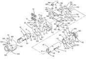
- FIG. 2 is an exploded view showing all component parts of a drive mechanism of the cylinder lock in an unassembled state
- FIG. 3 is another exploded view showing the unassembled component parts of the drive mechanism except inner and outer drive spindles and a latch retractor;
- FIG. 4 is a partly exploded view showing that all parts of the drive mechanism are assembled together except an outer shell of the drive mechanism;
- FIG. 5 is an exploded perspective view showing an outer handle, an outer drive spindle and a reinforcing ring;
- FIG. 6 is a perspective view showing the components of FIG. 5 in an assembled state.
- a cylinder lock mountable on a door panel including a drive mechanism 6 having an inner end connected to an inner rose 4 and an inner handle 2 , and an outer end connected to an outer rose 5 and an outer handle 1 .
- the drive mechanism 6 includes a latch retractor housing 61 made up of a base 64 , an inner cover plate 65 , and an outer cover plate 75 .
- the base 64 has upper and lower plates 644 , and a vertical plate 645 connected between the upper and lower plates 644 .
- the vertical plate 645 has two retention studs 643 (only one is shown).
- the upper and lower plates 644 bridge the inner and outer cover plates 65 , 75 .
- Each of the upper and lower plates 644 has two opposite ends respectively formed with two pairs of anchoring tabs 642 .
- Each anchoring tab 642 has a hook 641 .
- the anchoring tabs 642 extend outward through the inner and outer cover plates 65 , 75 .
- the inner cover plate 65 has a central hole 651 , and upper and lower projections 654 projecting from upper and lower edges of the inner cover plate 65 .
- Each projection 654 has an edge notch 653 .
- Indentations 652 are formed in the inner cover plate 65 at left and right sides of each projection 654 for passage of the respective anchoring tabs 642 of the upper and lower plates 644 .
- the inner cover plate 65 is therefore coupled to the base 64 .
- the outer cover plate 75 has a central hole 751 and projections 754 projecting from upper and lower edges of the outer cover plate 75 .
- Each projection 754 has an edge notch 753 .
- Indentations 752 are formed in the outer cover plate 75 at left and right sides of each projection 754 for passage of the respective anchoring tabs 642 of the base 64 .
- the outer cover plate 75 is thus coupled to the base 64 .
- the inner and outer cover plates 65 , 75 and the base 64 cooperate to form the latch retractor housing 61 .
- the latch retractor housing 61 encases a latch retractor 71 that has a linking part 713 to connect a latch mechanism 3 so that a latch 32 can be pulled inward.
- a receiving part 712 is provided at a rear side of the latch retractor 71 .
- a bearing part 711 is disposed between the linking part 713 and the receiving part 712 .
- the latch retractor 71 further has a positioning member 72 which is provided with two retaining elements 721 and which is assembled within the receiving part 712 , and two springs 73 each positioned between one of retaining elements 721 and one of the retention studs 643 of the base 64 .
- the springs 73 serve as a resilient support for the latch retractor 71 .
- the drive mechanism 6 further includes an inner drive spindle 8 , an outer drive spindle 9 , a sleeve 62 , an outer shell 63 , a reinforcing ring 10 , and two rigid coupling members 66 .
- the outer drive spindle 9 has a turning tab 91 at one end thereof to abut against the bearing part 711 of the latch retractor 71 , two diametrically opposite first protrusions 92 (only one is shown) projecting radially from the outer drive spindle 9 , and a second protrusion 93 projecting radially from the outer drive spindle 9 between the first protrusions 92 .
- the first and second protrusions 92 , 93 are proximate to the turning tab 91 .
- the outer drive spindle 9 is inserted partially into a tubular end portion 13 of the outer handle 1 .
- a resiliently supported handle retainer 94 is disposed at the middle of the outer drive spindle 9 . When the outer drive spindle 9 is inserted into the tubular end portion 13 of the outer handle 1 , the handle retainer 94 engages a slot 12 formed in the outer handle 1 .
- the inner drive spindle 8 has a turning tab 81 at one end thereof to abut against the bearing part 711 of the latch retractor 71 . Another end of the inner drive spindle 8 is connected directly to the inner handle 2 .
- the inner drive spindle 8 further has a spring-supported handle retainer 83 .
- the handle retainer 83 engages a hole 22 in the inner handle 2 when the inner drive spindle 8 is inserted into a central hole 21 of the inner handle 2 , thereby connecting the inner handle 2 to the inner drive spindle 8 .
- a ring 82 is sleeved around the inner drive spindle 8 .
- the outer drive spindle 9 has a portion inserted into the tubular end portion 13 of the outer handle 1 .
- the reinforcing ring 10 has a central hole 104 and is sleeved around another portion of the outer drive spindle 9 .
- One end of the reinforcing ring 10 has two diametrically opposite first cutouts 101 , and a second cutout 103 between the first cutouts 101 .
- the other end of the reinforcing ring 10 has two diametrically opposite fingers 102 projecting axially therefrom.
- the first cutouts 101 engage the respective first protrusions 92 of the outer drive spindle 9
- the fingers 102 engage respectively third cutouts 11 that are formed in the tubular end portion 13 of the outer handle 1 at two diametrically opposite positions.
- the second cutout 103 of the reinforcing ring 10 engages the second protrusion 93 of the outer drive spindle 9 .
- the sleeve 62 is a hollow cylinder and has a central hole 623 for extension of the outer drive spindle 9 .
- the sleeve 62 further has a flange 624 that extends annularly and radially from one end of the sleeve 62 .
- a pair of edge notches 621 and four apertures 622 are formed in the flange 624 .
- the apertures 622 permit extension of the hooks 641 of the base 64 .
- the hooks 641 are bent after extending through the respective apertures 622 so that the sleeve 62 is fixed to the latch retractor housing 61 .
- the edge notches 621 of the sleeve 62 are aligned axially with the respective edge notches 753 formed in the outer cover plate 75 .
- the rigid coupling members 66 are offset from and substantially parallel to a rotation axis of the inner and outer drive spindles 8 , 9 .
- the rigid coupling members 66 are formed as tubes 660 which are disposed at two diametrically opposite positions and each of which engages the aligned edge notches 653 , 753 of the latch retractor housing 61 and the edge notches 621 of the sleeve 62 .
- Each tube 660 has two opposite ends respectively provided with circumferentially extending first and second slots 661 , 662 .
- each tube 660 engages the respective edge notch 653 in the inner cover plate 65
- the second slot 662 thereof engages the respective edge notch 753 on the outer cover plate 75 and the respective edge notch 621 in the sleeve 62
- Each tube 66 further has an internal thread 663 .
- the outer shell 63 is substantially cylindrical and has a large tubular part 630 , a small tubular part 634 , and a shoulder plate 631 formed between the large and small tubular parts 630 , 634 .
- the shoulder plate 631 has four apertures 632 , and two screw holes 633 .
- the small tubular part 634 is sleeved around the inner driver spindle 8 .
- the large tubular part 630 encases the latch retractor housing 61 by associating with the flange 624 of the sleeve 62 .
- the large tubular part 630 is disposed around the latch retractor housing 61 , the anchoring tabs 642 extend through the inner and outer cover plates 65 , 75 , and the hooks 641 engaged in the respective apertures 622 in the flange 624 and the respective apertures 632 formed in the shoulder plate 631 .
- the screw holes 633 in the shoulder plate 631 are aligned with the respective internal threads 663 of the tubes 660 , and the screws 41 are inserted into the respective holes 42 of the inner rose 4 , the respective screw holes 633 and the respective internal threads 663 .
- the outer shell 63 further has a connecting part 635 in the large tubular part 630 .
- the connecting part 635 engages hooks 31 (only one is shown) of the latch mechanism 3 , whereas the linking part 713 of the latch retractor 71 is connected to the latch 32 .
- the outer drive spindle 9 moves the latch retractor 71 , thereby moving the latch 32 to a retracted position.
- the latch retractor 71 returns to its extended position by the action of the springs 73 so that the latch 32 returns to its protruding position.
- the rigid coupling members 66 (tubes 660 ) couple together the sleeve 62 and the inner and outer cover plates 65 , 75 , the entire assembly of the cylinder lock is reinforced in terms of torsional strength, compression strength and tensile strength so that the cylinder lock can resist stresses induced upon frequent movements of the outer handle 1 and the outer drive spindle 9 .
- the reinforcing ring 10 provides a coupling force between the outer handle 1 and the outer drive spindle 9 , the torsional strength of the outer drive spindle 9 is further increased.
- the reinforcing ring 10 may also be used to reinforce the inner drive spindle 8 by coupling the inner drive spindle 8 to the inner handle 2 .
Landscapes
- Automotive Seat Belt Assembly (AREA)
- Lock And Its Accessories (AREA)
Abstract
Description
Claims (18)
Priority Applications (1)
| Application Number | Priority Date | Filing Date | Title |
|---|---|---|---|
| US12/051,902 US8182005B2 (en) | 2007-01-12 | 2008-03-20 | Cylinder lock with reinforcements to improve structural strength |
Applications Claiming Priority (3)
| Application Number | Priority Date | Filing Date | Title |
|---|---|---|---|
| TW095201062 | 2006-01-16 | ||
| TW95201062U | 2006-01-16 | ||
| TW95201062U TWM294541U (en) | 2006-01-16 | 2006-01-16 | Structure of door lock |
Related Child Applications (1)
| Application Number | Title | Priority Date | Filing Date |
|---|---|---|---|
| US12/051,902 Continuation-In-Part US8182005B2 (en) | 2007-01-12 | 2008-03-20 | Cylinder lock with reinforcements to improve structural strength |
Publications (2)
| Publication Number | Publication Date |
|---|---|
| US20070182169A1 US20070182169A1 (en) | 2007-08-09 |
| US7748758B2 true US7748758B2 (en) | 2010-07-06 |
Family
ID=37765820
Family Applications (1)
| Application Number | Title | Priority Date | Filing Date |
|---|---|---|---|
| US11/652,834 Active 2028-11-01 US7748758B2 (en) | 2006-01-16 | 2007-01-12 | Cylinder lock having improved torsional strength |
Country Status (3)
| Country | Link |
|---|---|
| US (1) | US7748758B2 (en) |
| CA (1) | CA2573895C (en) |
| TW (1) | TWM294541U (en) |
Cited By (10)
| Publication number | Priority date | Publication date | Assignee | Title |
|---|---|---|---|---|
| US20080168809A1 (en) * | 2007-01-12 | 2008-07-17 | Cheng-Chung Liu | Cylinder lock with reinforcements to improve structural strength |
| US20110185777A1 (en) * | 2010-02-04 | 2011-08-04 | Cmech (Guangzhou) Industrial Ltd. | Side-hung door or window single latch lock |
| US20120061974A1 (en) * | 2010-09-09 | 2012-03-15 | Laverty Edward T | Cavity door end pull latch set and lock set |
| US20140062098A1 (en) * | 2012-09-05 | 2014-03-06 | Kia Motors Corporation | Two step link hood latch apparatus for vehicle |
| US20140196509A1 (en) * | 2013-01-15 | 2014-07-17 | Townsteel, Inc. | Attack-Thwarting Cylindrical Lockset |
| US9528300B2 (en) | 2012-03-14 | 2016-12-27 | Townsteel, Inc. | Cylindrical lockset |
| US10151125B2 (en) * | 2014-09-11 | 2018-12-11 | New York Air Brake, LLC | Hatch cover lock |
| US10316544B2 (en) | 2015-10-09 | 2019-06-11 | Endura Products, Inc. | Return cartridge for door handles |
| US11053711B2 (en) * | 2015-08-20 | 2021-07-06 | Assa Abloy Limited | Door latch installation |
| US11131118B2 (en) * | 2015-09-02 | 2021-09-28 | Tnbt Holdings Pty Ltd | Latchbolt retractor, a latchbolt assembly, and an assembly for a lockset |
Families Citing this family (7)
| Publication number | Priority date | Publication date | Assignee | Title |
|---|---|---|---|---|
| US20080307836A1 (en) * | 2007-06-14 | 2008-12-18 | Hyundae Metal Co., Ltd. | Door handle module and door lock using the same |
| IT1390950B1 (en) * | 2008-08-29 | 2011-10-27 | Polo Srl | SAFETY CHISURA DEVICE FOR DRAWERS AND DOORS. |
| US20110047756A1 (en) * | 2009-08-27 | 2011-03-03 | Fangchang Fan | Reversing Handle Structure |
| US9267310B2 (en) * | 2010-12-20 | 2016-02-23 | Industrilås i NässjöAB | Handle assembly for double-walled door |
| US8939477B2 (en) | 2011-04-22 | 2015-01-27 | Schlage Lock Company | Clutch mechanism for a lock assembly |
| TWI485312B (en) * | 2012-03-14 | 2015-05-21 | Townsteel Inc | Cylindrical lockset |
| CA3129004A1 (en) | 2019-02-11 | 2020-08-20 | Spectrum Brands, Inc. | Support structure for handle assembly |
Citations (23)
| Publication number | Priority date | Publication date | Assignee | Title |
|---|---|---|---|---|
| US323393A (en) * | 1885-08-04 | Knob attachment | ||
| US2538688A (en) | 1946-09-24 | 1951-01-16 | Yale & Towne Mfg Co | Lock casing |
| US4201069A (en) * | 1977-11-29 | 1980-05-06 | Akira Katayama | Knob for a door lock |
| US4428212A (en) * | 1981-10-08 | 1984-01-31 | Best Lock Corporation | Cylinder lock retractor and chassis assembly |
| US5335948A (en) | 1992-10-16 | 1994-08-09 | Corbin Russwin, Inc. | Cylindrical lockset |
| US5845522A (en) * | 1997-03-10 | 1998-12-08 | Shen; Mu-Lin | Fastening arrangement for a cylindrical lock |
| US6141998A (en) * | 1998-01-15 | 2000-11-07 | Seo; Jung-Yoon | Door lock device |
| US20010023600A1 (en) * | 2000-01-19 | 2001-09-27 | Pompeii Dario L. | Lock architecture |
| US20020104345A1 (en) * | 2001-02-06 | 2002-08-08 | Taiwan Fu Hsing Industrial Co., Ltd. | Outer handle structure of a lock which may be idle |
| US6470721B2 (en) | 2001-01-05 | 2002-10-29 | Taiwan Fu Hsing Industrial Co., Ltd. | Strength reinforcing structure of a lock outer handle |
| US20030056556A1 (en) * | 2001-09-21 | 2003-03-27 | Park Dea San | Lever door lock device |
| US6553799B2 (en) * | 2001-02-23 | 2003-04-29 | Schlage Lock Company | Push button door locking mechanism |
| US6615630B2 (en) * | 2000-12-05 | 2003-09-09 | Tong-Lung Metal Industry Co., Ltd. | Door lock |
| US6698803B2 (en) * | 2001-01-12 | 2004-03-02 | Schlage Lock Company | Door latching mechanism |
| US20040168491A1 (en) * | 2001-07-25 | 2004-09-02 | Triangle Brass Manufacturing Company, Inc. | Anti-vandal door lock apparatus |
| US6893059B2 (en) * | 2002-11-25 | 2005-05-17 | Shen Mu-Lin | Cylindrical lock with improved resistance to torque |
| US6935148B2 (en) * | 2002-07-29 | 2005-08-30 | Tung Lung Metal Industry Co., Ltd. | Lock engaging-and-disengaging mechanism |
| US20060042333A1 (en) * | 2004-08-24 | 2006-03-02 | Wen-Pin Wu | Doorknob |
| US7066507B2 (en) * | 2003-01-29 | 2006-06-27 | Tong Lung Metal Industry Co., Ltd. | Post-removable construction of a door lock device |
| US20070028657A1 (en) | 2005-08-05 | 2007-02-08 | Taiwan Fu Hsing Industrial Co., Ltd. | Strengthened lock structure |
| US20070096479A1 (en) | 2005-10-27 | 2007-05-03 | Taiwan Fu Hsing Industrial Co., Ltd. | Positioning structure for a door lock mechanism |
| US20080168809A1 (en) * | 2007-01-12 | 2008-07-17 | Cheng-Chung Liu | Cylinder lock with reinforcements to improve structural strength |
| US20090025438A1 (en) * | 2007-07-27 | 2009-01-29 | Lan-Kun Don | Lockset having an electrically operated clutch to control transmission of rotation from an outside handle to an outside spindle |
-
2006
- 2006-01-16 TW TW95201062U patent/TWM294541U/en not_active IP Right Cessation
-
2007
- 2007-01-12 US US11/652,834 patent/US7748758B2/en active Active
- 2007-01-15 CA CA2573895A patent/CA2573895C/en active Active
Patent Citations (25)
| Publication number | Priority date | Publication date | Assignee | Title |
|---|---|---|---|---|
| US323393A (en) * | 1885-08-04 | Knob attachment | ||
| US2538688A (en) | 1946-09-24 | 1951-01-16 | Yale & Towne Mfg Co | Lock casing |
| US4201069A (en) * | 1977-11-29 | 1980-05-06 | Akira Katayama | Knob for a door lock |
| US4428212A (en) * | 1981-10-08 | 1984-01-31 | Best Lock Corporation | Cylinder lock retractor and chassis assembly |
| US5335948A (en) | 1992-10-16 | 1994-08-09 | Corbin Russwin, Inc. | Cylindrical lockset |
| US5845522A (en) * | 1997-03-10 | 1998-12-08 | Shen; Mu-Lin | Fastening arrangement for a cylindrical lock |
| US6141998A (en) * | 1998-01-15 | 2000-11-07 | Seo; Jung-Yoon | Door lock device |
| US20010023600A1 (en) * | 2000-01-19 | 2001-09-27 | Pompeii Dario L. | Lock architecture |
| US6615630B2 (en) * | 2000-12-05 | 2003-09-09 | Tong-Lung Metal Industry Co., Ltd. | Door lock |
| US6470721B2 (en) | 2001-01-05 | 2002-10-29 | Taiwan Fu Hsing Industrial Co., Ltd. | Strength reinforcing structure of a lock outer handle |
| US6698803B2 (en) * | 2001-01-12 | 2004-03-02 | Schlage Lock Company | Door latching mechanism |
| US20020104345A1 (en) * | 2001-02-06 | 2002-08-08 | Taiwan Fu Hsing Industrial Co., Ltd. | Outer handle structure of a lock which may be idle |
| US6497126B2 (en) * | 2001-02-06 | 2002-12-24 | Taiwan Fu Hsing Industrial Co., Ltd. | Outer handle structure of a lock which may be idle |
| US6553799B2 (en) * | 2001-02-23 | 2003-04-29 | Schlage Lock Company | Push button door locking mechanism |
| US20040168491A1 (en) * | 2001-07-25 | 2004-09-02 | Triangle Brass Manufacturing Company, Inc. | Anti-vandal door lock apparatus |
| US20040187531A1 (en) * | 2001-07-25 | 2004-09-30 | Triangle Brass Manufacturing Company, Inc. | Anti-vandal door lock apparatus |
| US20030056556A1 (en) * | 2001-09-21 | 2003-03-27 | Park Dea San | Lever door lock device |
| US6935148B2 (en) * | 2002-07-29 | 2005-08-30 | Tung Lung Metal Industry Co., Ltd. | Lock engaging-and-disengaging mechanism |
| US6893059B2 (en) * | 2002-11-25 | 2005-05-17 | Shen Mu-Lin | Cylindrical lock with improved resistance to torque |
| US7066507B2 (en) * | 2003-01-29 | 2006-06-27 | Tong Lung Metal Industry Co., Ltd. | Post-removable construction of a door lock device |
| US20060042333A1 (en) * | 2004-08-24 | 2006-03-02 | Wen-Pin Wu | Doorknob |
| US20070028657A1 (en) | 2005-08-05 | 2007-02-08 | Taiwan Fu Hsing Industrial Co., Ltd. | Strengthened lock structure |
| US20070096479A1 (en) | 2005-10-27 | 2007-05-03 | Taiwan Fu Hsing Industrial Co., Ltd. | Positioning structure for a door lock mechanism |
| US20080168809A1 (en) * | 2007-01-12 | 2008-07-17 | Cheng-Chung Liu | Cylinder lock with reinforcements to improve structural strength |
| US20090025438A1 (en) * | 2007-07-27 | 2009-01-29 | Lan-Kun Don | Lockset having an electrically operated clutch to control transmission of rotation from an outside handle to an outside spindle |
Cited By (17)
| Publication number | Priority date | Publication date | Assignee | Title |
|---|---|---|---|---|
| US20080168809A1 (en) * | 2007-01-12 | 2008-07-17 | Cheng-Chung Liu | Cylinder lock with reinforcements to improve structural strength |
| US8182005B2 (en) * | 2007-01-12 | 2012-05-22 | Tong Lung Metal Industry Co., Ltd. | Cylinder lock with reinforcements to improve structural strength |
| US20110185777A1 (en) * | 2010-02-04 | 2011-08-04 | Cmech (Guangzhou) Industrial Ltd. | Side-hung door or window single latch lock |
| US8419081B2 (en) * | 2010-02-04 | 2013-04-16 | Cmech (Guangzhou) Industrial, Ltd. | Side-hung door or window single latch lock |
| US20120061974A1 (en) * | 2010-09-09 | 2012-03-15 | Laverty Edward T | Cavity door end pull latch set and lock set |
| US9528300B2 (en) | 2012-03-14 | 2016-12-27 | Townsteel, Inc. | Cylindrical lockset |
| US20140062098A1 (en) * | 2012-09-05 | 2014-03-06 | Kia Motors Corporation | Two step link hood latch apparatus for vehicle |
| US9187936B2 (en) * | 2012-09-05 | 2015-11-17 | Hyundai Motor Company | Two step link hood latch apparatus for vehicle |
| US9394722B2 (en) * | 2013-01-15 | 2016-07-19 | Townsteel, Inc. | Attack-thwarting cylindrical lockset |
| US20160305160A1 (en) * | 2013-01-15 | 2016-10-20 | Townsteel, Inc. | Retractor assembly for a cylindrical lockset |
| US20140196509A1 (en) * | 2013-01-15 | 2014-07-17 | Townsteel, Inc. | Attack-Thwarting Cylindrical Lockset |
| US9732542B2 (en) * | 2013-01-15 | 2017-08-15 | Townsteel, Inc. | Retractor assembly for a cylindrical lockset |
| US10151125B2 (en) * | 2014-09-11 | 2018-12-11 | New York Air Brake, LLC | Hatch cover lock |
| US11053711B2 (en) * | 2015-08-20 | 2021-07-06 | Assa Abloy Limited | Door latch installation |
| US11131118B2 (en) * | 2015-09-02 | 2021-09-28 | Tnbt Holdings Pty Ltd | Latchbolt retractor, a latchbolt assembly, and an assembly for a lockset |
| US10316544B2 (en) | 2015-10-09 | 2019-06-11 | Endura Products, Inc. | Return cartridge for door handles |
| US11035148B2 (en) | 2015-10-09 | 2021-06-15 | Endura Products, Llc | Return cartridge for door handles |
Also Published As
| Publication number | Publication date |
|---|---|
| CA2573895A1 (en) | 2007-07-16 |
| US20070182169A1 (en) | 2007-08-09 |
| CA2573895C (en) | 2013-04-09 |
| TWM294541U (en) | 2006-07-21 |
Similar Documents
| Publication | Publication Date | Title |
|---|---|---|
| US7748758B2 (en) | Cylinder lock having improved torsional strength | |
| US8182005B2 (en) | Cylinder lock with reinforcements to improve structural strength | |
| CA2666704C (en) | Cylinder lock having a reinforcement structure coupled to an outer rose disc | |
| US7137657B2 (en) | Reinforced apparatus for a lever handle of a door lock | |
| KR101755226B1 (en) | Spindle of door handle | |
| US8256253B2 (en) | Cylindrical lock | |
| US20090146439A1 (en) | Ironmongery | |
| US6623053B1 (en) | Inside locking device of flat handle lock | |
| US6357807B1 (en) | Door lock | |
| US6676178B2 (en) | Door lock assembly having escutcheon with removable posts | |
| US11299917B2 (en) | Vehicle door latch device | |
| US20060156770A1 (en) | Restraining plate cooperating with a locking/unlocking control bar for use in a door lock mechanism | |
| US20080098775A1 (en) | Door lock assembly that causes a handle to idle when placed in a locking position | |
| US20080083253A1 (en) | Door lock assembly with which a door cannot be unlatched by rotating a handle | |
| US20060208507A1 (en) | Latch driving unit for a door lock | |
| US20040227361A1 (en) | Restoring structure of a lock | |
| US7357010B1 (en) | Plug assembly for a door lock | |
| US20050223763A1 (en) | Returning device for lock | |
| JP2683324B2 (en) | Door handle mounting seat | |
| US7047775B2 (en) | Assembling structure for a door lock | |
| US20070163312A1 (en) | Reinforced handle assembly for lock | |
| WO2015098542A1 (en) | Shift lever device | |
| US20050125954A1 (en) | Face plate and door handle assembly | |
| CA2626410C (en) | Cylinder lock with reinforcements to improve structural strength | |
| CN208518462U (en) | Lock |
Legal Events
| Date | Code | Title | Description |
|---|---|---|---|
| AS | Assignment |
Owner name: TONG-LUNG METAL INDUSTRY CO., LTD., TAIWAN Free format text: ASSIGNMENT OF ASSIGNORS INTEREST;ASSIGNORS:FANG, JEFF;LIU, CHENG-CHUNG;DON, LAN-KUN;REEL/FRAME:018801/0595 Effective date: 20061229 |
|
| STCF | Information on status: patent grant |
Free format text: PATENTED CASE |
|
| FPAY | Fee payment |
Year of fee payment: 4 |
|
| AS | Assignment |
Owner name: STANLEY SECURITY SOLUTIONS TAIWAN LTD., TAIWAN Free format text: ASSIGNMENT OF ASSIGNORS INTEREST;ASSIGNOR:TONG LUNG METAL INDUSTRY CO., LTD.;REEL/FRAME:033750/0497 Effective date: 20140827 |
|
| AS | Assignment |
Owner name: TUNG LUNG HARDWARE MANUFACTURING CO., LTD., TAIWAN Free format text: CHANGE OF NAME;ASSIGNOR:STANLEY SECURITY SOLUTIONS TAIWAN LTD.;REEL/FRAME:042763/0092 Effective date: 20170501 |
|
| FEPP | Fee payment procedure |
Free format text: ENTITY STATUS SET TO SMALL (ORIGINAL EVENT CODE: SMAL) |
|
| MAFP | Maintenance fee payment |
Free format text: PAYMENT OF MAINTENANCE FEE, 8TH YR, SMALL ENTITY (ORIGINAL EVENT CODE: M2552) Year of fee payment: 8 |
|
| AS | Assignment |
Owner name: TLHM CO., LTD., TAIWAN Free format text: CHANGE OF NAME;ASSIGNOR:TUNG LUNG HARDWARE MANUFACTURING CO., LTD.;REEL/FRAME:044907/0254 Effective date: 20170804 |
|
| MAFP | Maintenance fee payment |
Free format text: PAYMENT OF MAINTENANCE FEE, 12TH YR, SMALL ENTITY (ORIGINAL EVENT CODE: M2553); ENTITY STATUS OF PATENT OWNER: SMALL ENTITY Year of fee payment: 12 |