US7748508B2 - Wheeled luggage case - Google Patents
Wheeled luggage case Download PDFInfo
- Publication number
- US7748508B2 US7748508B2 US10/587,415 US58741505A US7748508B2 US 7748508 B2 US7748508 B2 US 7748508B2 US 58741505 A US58741505 A US 58741505A US 7748508 B2 US7748508 B2 US 7748508B2
- Authority
- US
- United States
- Prior art keywords
- wheel assembly
- luggage
- steering wheel
- case
- receptacle
- Prior art date
- Legal status (The legal status is an assumption and is not a legal conclusion. Google has not performed a legal analysis and makes no representation as to the accuracy of the status listed.)
- Expired - Fee Related, expires
Links
Images


Classifications
-
- A—HUMAN NECESSITIES
- A45—HAND OR TRAVELLING ARTICLES
- A45C—PURSES; LUGGAGE; HAND CARRIED BAGS
- A45C5/00—Rigid or semi-rigid luggage
- A45C5/14—Rigid or semi-rigid luggage with built-in rolling means
-
- A—HUMAN NECESSITIES
- A45—HAND OR TRAVELLING ARTICLES
- A45C—PURSES; LUGGAGE; HAND CARRIED BAGS
- A45C5/00—Rigid or semi-rigid luggage
- A45C5/04—Trunks; Travelling baskets
-
- A—HUMAN NECESSITIES
- A45—HAND OR TRAVELLING ARTICLES
- A45C—PURSES; LUGGAGE; HAND CARRIED BAGS
- A45C13/00—Details; Accessories
- A45C13/38—Luggage carriers
- A45C13/385—Luggage carriers with rolling means
-
- A—HUMAN NECESSITIES
- A45—HAND OR TRAVELLING ARTICLES
- A45C—PURSES; LUGGAGE; HAND CARRIED BAGS
- A45C5/00—Rigid or semi-rigid luggage
- A45C5/14—Rigid or semi-rigid luggage with built-in rolling means
- A45C5/141—Rigid or semi-rigid luggage with built-in rolling means the rolling means being formed by the trunk itself
-
- A—HUMAN NECESSITIES
- A45—HAND OR TRAVELLING ARTICLES
- A45C—PURSES; LUGGAGE; HAND CARRIED BAGS
- A45C13/00—Details; Accessories
- A45C13/26—Special adaptations of handles
- A45C13/262—Special adaptations of handles for wheeled luggage
-
- A—HUMAN NECESSITIES
- A45—HAND OR TRAVELLING ARTICLES
- A45C—PURSES; LUGGAGE; HAND CARRIED BAGS
- A45C5/00—Rigid or semi-rigid luggage
- A45C5/14—Rigid or semi-rigid luggage with built-in rolling means
- A45C5/146—Rigid or semi-rigid luggage with built-in rolling means retractable
Definitions
- This invention relates to traveller's luggage cases and more particularly to luggage cases which are equipped with wheels and a push-handle to facilitate movement of the case along a floor, walkway or the like.
- Rental luggage carts are available at certain sites of this kind but the renting process is itself an inconvenience and such carts do not remain with the traveller after leaving the site of rental.
- wheeled luggage carriers which typically have a lightweight and foldable construction to facilitate handling and storage of the device when it is not in use, have been used.
- An example of such a carrier is shown in FIG. 1 .
- Such carriers are essentially small hand trucks of the type which have a platform on which the luggage case is rested, a pair of wheels which extend below one edge region of the platform and a handle which extends upward from the edge region. The user grasps and tilts the handle to lift the platform and luggage case upward from the underlying floor or the like and the carrier may then be pulled or pushed to the destination of the case.
- Such carriers are helpful but are not entirely free of inconveniences of their own.
- the carrier is not self-stabilized and it is not entirely self-supporting during movement. A person who is pulling or pushing such a carrier must continually exert additional effort in order to hold the carrier at the tilted orientation that enables it to be travelled along the floor or other surface. In the absence of such effort by the user, gravity pivots the carrier until either the platform or the handle itself contacts the floor.
- Retractable handles were built into wheeled luggage cases to facilitate movement of the case as shown in FIG. 3 .
- the handle When the handle is extended, the unit may be tilted about the wheels and be operated in essentially the same manner as the previously discussed luggage case carriers.
- the holding mechanisms are not always able to support the weight of the often heavy luggage for prolonged use which results in failure of the holding mechanism and luggage of this type will often have to be repaired or replaced on a regular basis.
- a wheeled luggage case having a luggage receptacle, the receptacle having two opposing major walls and having end walls forming a luggage compartment, whereof a major wall of the receptacle is adapted to serve as a bottom wall that faces the ground during use of the wheels, wherein said luggage case further comprises:
- the opposing major walls of the case are the opposing walls of the case that are of largest surface area.
- the handle means is located at the same end of the luggage receptacle as the support wheels.
- the steering wheel assembly in the active position, extends further from the base wall than the support wheels.
- This arrangement whereby the luggage receptacle is tilted back towards the support wheels displaces the centre of gravity towards the user pushing the case and makes it easier to push.
- This arrangement also displaces the centre of gravity away from the steering wheels, thus off-loading it and making it easier to steer.
- the wheeled luggage comprises two support wheels and one retractable steering wheel assembly in a tricycle wheel configuration.
- This tricycle configuration confers additional manoeuvrability with good stability while minimising total luggage weight and optimising ease and convenience of operating the wheeling system.
- This arrangement optimises manoeuvrability with good stability while minimising total luggage weight and optimising ease and convenience of operating the wheeling system.
- the support wheels are only ‘activated’ when steering wheel(s) is extended and tilts the case backwards. This arrangement optimises the ease and convenience of activating and inactivating the wheeling system and minimising the weight of wheeling system.
- the retractable wheel assembly is pivotally mounted or mounted in a slotted fashion.
- the luggage receptacle incorporates recesses in both the end wall and the bottom wall adapted to accommodate the steering wheel assembly in the inactive and active positions respectively.
- the wheel of the steering wheel assembly is pivotally mounted in the assembly such that it can rotate about its own axis and about an axis substantially perpendicular to it. This arrangement facilitates steering.
- the steering wheel assembly when in an active position, is supported by a support surface on the base wall of the case.
- the support surface is recessed into the base wall of the case.
- the support surface for the wheel assembly in the base wall is located at an acute angle to the base wall of the case with respect to a line between the front of the case and the support wheels so that the support surface is about parallel to the ground surface.
- the steering wheel assembly and support wheels are so sized and shaped such that, with the steering wheel assembly in its active position, the base wall forms an acute angle with respect to the surface the case is standing on, the acute angle extending away from the support wheels.
- This arrangement displaces the centre of gravity of the case contents toward the support wheels and towards the handle and the user. This makes the case easier to push the load. At the same time, this arrangement displaces the centre of gravity of the case contents away from the steering wheel to offload it and makes it easier to steer the case.
- the broad base of the case is parallel to the supporting ground on a ‘stopper’ at one end of the case base and on support wheels on the other end.
- the front steering wheel in extended in the active position, it tilts the case and automatically ‘activates’ the rear support wheels into play.
- the handle means can be moved between an active position at which the handle extends outwards from the luggage receptacle and can be engaged by the user at an inactive position at which the handle is contained substantially within the luggage receptacle.
- the luggage case can be carried by a handle placed at the long narrow surface like an ordinary carrying case.
- the handle when the wheeling system is activated and the case tilted backwards, the handle is also tilted backwards away from the posterior case surface to allow for sufficient striding space.
- the posterior surface of the case is optionally recessed to provide additional striding space.
- the case is made of robust material not only for durability and protection of the contents, but to be able to provide a platform for carrying other pieces of luggage stacked on top of it.
- the case can act as a cart/trolley for carrying other pieces of luggage.
- the case can be conveniently converted into a push pram for babies or toddlers with suitable accessorial and safety attachment.
- a simple braking system is installed for safety and convenience purposes.
- FIG. 1 illustrates a prior art wheeled luggage carrier
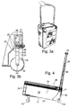
- FIG. 2 illustrates a prior art wheeled luggage case
- FIG. 3 a illustrates a prior art wheeled luggage case with handle
- FIG. 3 b illustrates a close up view of prior art retractable wheel
- FIG. 4 illustrates a side view of a luggage case according to one embodiment of the present invention where the steering wheel and handle are in an active position
- FIG. 4 a illustrates a close up view of the steering wheel assembly
- FIG. 5 illustrates a side view of the luggage case of FIG. 4 where the steering wheel assembly is moving towards an inactive position
- FIG. 6 shows a side view of the luggage case of FIG. 4 in between an active and inactive position
- FIG. 7 shows a side view of the luggage case of FIG. 4 in an inactive position
- FIG. 8 shows a perspective view of the luggage case of the first embodiment
- FIG. 9 illustrates a slightly different embodiment of the invention.
- FIGS. 10 to 15 illustrate a further slightly different embodiment of the invention.
- FIGS. 16 to 19 illustrate a yet further embodiment.
- FIGS. 1-3 show various prior art designs for mounting a luggage case on wheels.
- FIG. 1 shows a foldable frame upon which luggage would be placed to facilitate movement.
- FIG. 2 shows a case with wheels mounted at one end of a narrow edge surface.
- FIG. 3 a shows an alternate wheel mounted case with a retractable handle to facilitate movement. All of these designs suffer from the various drawbacks above.
- FIG. 3 b An example of a typical retraction means is shown in FIG. 3 b.
- a wheel 20 is partially situated in an alcove 21 formed in the frame of the receptacle 22 .
- the axle 23 of the wheel 20 engages a fork 24 having a shank 25 that extends up into a vertical passage 26 in a thickened portion of the frame 27 .
- the shank and passage are of sufficient length to enable the raising of the wheel to the point where the lower edge of the wheel is above the level of the underside of the receptacle.
- the retraction means includes a pin 28 which extends through a passage in the frame and which may be entered into either of a pair of bores 29 which corresponds with either the raised or lowered position.
- a compression spring acts against a flange to resist withdrawal of the pin.
- the multiple retractable wheels along with the holding mechanisms are flimsy, cumbersome and inconvenient to activate and retract. More pertinently, they make the whole case too heavy for practical purposes.
- FIGS. 4-10 shows a wheeled luggage case 30 according to one embodiment of the present invention.
- FIG. 4 shows a side view of a luggage case comprising a luggage receptacle 31 , support wheel assemblies 32 a ( 32 b is not shown), a steering wheel assembly 33 and a retractable handle 39 .
- the luggage receptacle 31 is defined by a base 34 , a front end wall 35 , a rear end wall 36 , a side wall 37 (the other side wall not shown) which forms a luggage compartment.
- the lid 38 spans the top of the compartment when the case is closed.
- Receptacle 31 and lid 38 may jointly have the general configuration and construction of a typical traveller's suitcase except for the specialised structural features which will be hereinafter described.
- the receptacle 31 and lid 38 jointly have a generally rectangular configuration. Both such components are formed of a durable material.
- the case 30 may, of course, have other shapes and be formed of other materials and is equally adaptable to any sized luggage case.
- the luggage receptacle 31 and lid 38 jointly have a length and a width which both exceed their height as this provides for maximum stability.
- the lid can be fastened to the luggage receptacle by various means known to those skilled in the art and there are various ways in which the lid can be held closed including but not limited to zips, locks, clasps or any holding means.
- the case 30 is designed to be wheeled along a floor, walkway or the like, it is preferably provided with a conventional hand grip (not shown) to enable carrying of the case when it is being moved for only a short distance.
- the invention is equally adaptable to luggage cases which have other forms of hinges, closures, latching means and provisions for carrying the case.
- a generally U-shaped retractable handle 39 enables the traveller to push the case 30 while walking in a normal upright posture.
- the handle has a pair of coplanar parallel arms 40 which can be retracted into a chamber 41 so that the top of the handle does not protrude beyond the lid 38 when not in use and does not interfere with storage of the case in restricted spaces.
- the opposite ends of the arms are linked by a cross member 42 which is grasped by the user during travel of the case.
- the handle 34 is extendible and contractible as each arm is formed by telescoping members. Means are provided to lock the arms in position during use which can optionally allow the traveller to select the degree of extension.
- the handle can be positioned during use and subsequently stored away when the case in not being used.
- the handle could be formed from a generally U-shaped pivoting or folding handle.
- the handle can easily be manufactured to various designs and the present invention encompasses any handle design.
- Spaced apart support wheel assemblies 32 a and 32 b are disposed at opposite side regions of the luggage receptacle 31 in proximity to the back end wall 36 of receptacle 31 and extend downward to contact the supporting surface. This can be seen more clearly in FIG. 8 .
- the inclination of the base of the case from the supporting surface tilts the handle bar backwards away from the posterior surface and postero-inferior edge of the case to provide striding space.
- a portion of the posterior surface of the case is optionally recessed to provide additional striding space (see drawing).
- a steering wheel assembly 33 is shown in FIG. 4 and a close up view of the steering wheel is shown in FIG. 4 a .
- the axle 43 of the wheel 44 is connected to a holding bracket 45 , which in turn is connected to a turning element 45 a which can pivot about a substantially vertical axis in order to self adjust to turns in the path of the travel case.
- the turning element is connected to a pivotally mounted section 46 which allows the steering wheel to be moved between an active position in which the steering wheel assembly 33 extends below the bottom wall of the luggage receptacle 34 and an inactive position in which the steering wheel assembly is substantially contained within the luggage receptacle and does not protrude significantly beyond the front wall 35 and does not interfere with storage of the case in restricted spaces.
- the luggage receptacle has a recess or opening 47 which is of sufficient size to receive the steering wheel assembly 33 .
- the wheel and turning element are in line during storage but any orientation could be used.
- the pivot 48 allows the pivotally mounting section to rotate between the active and inactive position. In the active position the top 49 of the pivotally mounting section 46 engages with a portion 50 of the support surface attached to the base 34 of the luggage receptacle 31 . In this example the portion 50 is recessed slightly. Because the entire top of the pivotally mounting section engages with the support surface at the base of the luggage receptacle forces acting on the steering wheel assembly will pass through the turning element and pivotally mounting section and dissipate into the support surface and the luggage receptacle itself. This greatly reduces the stress on any one section of the steering wheel assembly and as such greatly increases its durability and strength.
- portion 50 is angled by some 15° in a line from the pivot point away from the base of the case and into the body of the case.
- a consequence of this design is that during forward motion of the case the load on the steering wheel assembly is taken mostly on the surface of portion 50 which is in contact with the steering wheel assembly, rather than being transmitted entirely through the pivot point, which is the case in earlier retractable wheel assembly designs.
- the angle of portion 50 with respect to the base of the case is not critical. Any angle, for example 45°, could be used. Generally an angle of 15° ⁇ 10° is preferred.
- FIG. 4 shows that the steering wheel assembly 33 protrudes further from the base of the luggage receptacle than the support wheel assembly therefore when the steering wheel assembly is in an active position the luggage receptacle sits at an angle, the front end being higher than the back end which has a number of advantages.
- the angle means that a greater portion of the forces acting on the luggage receptacle will act though the support wheels, this has the effect that the luggage receptacle will appear lighter and will be easier to manoeuvre and steer through a fulcrum like effect.
- the angle means that if any articles are placed on top of the luggage receptacle they will naturally fall towards the handle which will mean that they will stay on top of the luggage receptacle more easily.
- FIG. 5 shows the luggage receptacle wherein the steering wheel assembly 33 is in a partially inactive position.
- FIG. 6 shows the luggage receptacle wherein the steering wheel assembly 33 is in an almost fully inactive position.
- the turning section 45 has been rotated perpendicularly to the direction of forward linear motion to facilitate complete retraction into the opening 47 .
- the retractable handle 39 is in a semi-retracted or inactive position.
- FIG. 7 shows the steering wheel assembly 33 and the handle 39 in an inactive position. Neither substantially protrude beyond the surface of the luggage receptacle.
- FIG. 9 shows an alternative embodiment of the invention which includes a stopper 49 attached to the underside of the base 34 of the luggage receptacle.
- the stopper could comprise a single, centred, stopper but more preferably a plurality (e.g. 2 or more) positioned so as to support the luggage receptacle in the inactive position. This means that when the steering wheel assembly 33 is in the inactive position the luggage receptacle will rest on the stopper 49 and not the base 34 .
- the stopper 49 is of a size to protrude substantially the same amount from the base as the support wheels which means that the luggage receptacle will be largely level when the steering wheel assembly 33 is in the inactive position. When the steering wheel assembly 33 is in the active position the stopper 49 will not interfere with the movement of the luggage case 30 .
- the self-supporting and self stabilizing characteristics of the wheeled luggage case make it suitable for transporting an infant in addition to the contents of the case.
- a child seat may be disposed on top of lid and be secured to the case Alternatively other luggage or items may be placed on top of the case.
- a simple braking system is installed for safety and convenience purposes.
- FIGS. 10 to 15 show a slightly different embodiment with modifications to the invention including a quick release latch 60 for releasing the steering wheel for use and a ring handle guide 61 for pulling out and also, suitably, retracting the steering wheel assembly back into the slot recess of the case.
- a latch mechanism here a spring-loaded ball catch lock, of the steering wheel L-frame on to the support surface at the base of the case can be used to prevent detachment during wheel lift-off and an L-shaped steering wheel frame to decrease likelihood of collapse of the steering wheel system, especially during lift-off and when engaging resistance during reversing.
- this embodiment of the case differs from the preceding embodiment in a number of respects. It will be seen that the case is moulded with reinforcing ribs and from FIG. 19 it will be seen that the handle bar arrangement has three uprights instead of two in order to give even greater strength to the handle. Furthermore, as can be seen from FIGS. 16 to 18 , the steering wheel assembly is housed wholly within a recess in the bottom wall of the case and which runs to the end wall but here there is no separate recess in the end wall, i.e. unlike the preceding embodiment the steering wheel assembly does not move from a recess in the end wall to a recess in the bottom wall.
- the pivotable castor wheel of the steering wheel assembly in this latest embodiment is generally accommodated in its recessed state lying along the channel shaped recess in the bottom wall and with the wheel in the orientation in which it would be when extended.
- the wheel In FIG. 17 , the wheel is seen in a partially extended state and in FIG. 18 it is seen fully retracted into the recess/channel.
- extension and retraction of the steering wheel assembly in this embodiment is through a simple single pivoting motion about pivot axis 48 ′ within the channel recess.
- this embodiment also has a latch mechanism to prevent detachment of the steering wheel assembly when in its operative position and which here is under user control through manual operation of the button 62 .
- the present invention provides a new design for the large size travel suitcase that is easily portable with minimal effort and is highly manoeuvrable, stable and convenient to use.
- the proposed suitcase is a light-weight, robust, trolley-type design with a retractable push handle and retractable wheels (e.g. see FIGS. 4 to 7 inclusive).
- the design with a wide base and a low centre of gravity is inherently more stable compared to various traditional suitcase designs. Unlike cases towed on wheels at an incline (e.g. U.S. Pat. No. 5,116,289), this design is self-stabilised and self-supporting during movement.
- a tricycle wheel configuration with two unidirectional rear wheels located one at each side and a single multidirectional front wheel, will confer maximum manoeuvrability (see FIG. 8 ).
- a retractable push handle will enable the suitcase to be carried in an upright manner like a conventional case, when the handle and wheels are retracted.
- the retractable handle can be easily manufactured to various design options.
- the retractable wheels allows the wheels to come into play only when needed and avoid potential damage of exposed wheels during luggage transfer.
- Prior U.S. Pat. No. 5,407,039 has multiple retractable wheels that are cumbersome and heavy.
- a third ‘flippable’ wheel in the front tilts the case to bring the rear wheels into play and enables the case to function as a cart tricycle (see diagram). This design minimises bulk and weight on the case itself and makes the case practical and convenient to use.
- the push-trolley suitcase design is more ergonomically suited for moving large and heavy loads. Furthermore, it is easier to push than to pull a heavy load.
- This push-trolley suitcase design enables one to cart a heavy suitcase load with more control and with much less effort. Furthermore, this trolley suitcase design can also be adapted for pulling purposes such as reversing from a right corner and reversing down from a step.
- the push trolley suitcase design can be used as a push trolley in itself.
- Other luggage can be piled on top of it and carted around as with the use of an airport or train station push trolley. This is possible with contemporary plastic that is tough, light-weight and strong.
- Other options include the use of canvass with aluminium skeletal frame reinforcement.
- the push trolley suitcase can conveniently be converted into a push pram for babies or toddlers with suitable accessorial and safety attachment.
- the base of suitcase is at an incline when the retractable wheel is in use. This helps to bring the hind-wheels into play, and shifts the centre of gravity backwards towards the hind-wheels to improve stability on the tricycle and manoeuvrability of the front multidirectional wheel. It also tilts the handle bar backwards to allow for foot clearance when walking and pushing the case and keeps the stacked luggage on the trolley in place.
- the L-shape wheel frame design confers stability to all directions of wheel movement, takes up minimal luggage space when retracted and resists compressive forces when in use and requires less material bulk.
- a retractable steering wheel assembly as illustrated in FIG. 4 and as described above could be employed in a luggage case where the steering wheel assembly and support wheels were of substantially equivalent size.
- the luggage case would be substantially parallel to the surface on which it was being wheeled.
Landscapes
- Purses, Travelling Bags, Baskets, Or Suitcases (AREA)
- Handcart (AREA)
- Addition Polymer Or Copolymer, Post-Treatments, Or Chemical Modifications (AREA)
- Crystals, And After-Treatments Of Crystals (AREA)
- Cash Registers Or Receiving Machines (AREA)
- Investigating, Analyzing Materials By Fluorescence Or Luminescence (AREA)
Abstract
Description
- (i) a plurality of support wheels located at one end of the bottom wall;
- (ii) a retractable steering wheel assembly, located on the bottom wall, distanced from the support wheels, said steering wheel assembly having at least one wheel and being moveable between an active position at which the wheel assembly extends below the bottom wall of the luggage receptacle or an inactive position at which the wheel assembly is substantially within the profile of the luggage receptacle; and
- (iii) a handle means located at one end of the luggage receptacle for steering, pushing, pulling and lifting purposes; the steering wheel assembly and support wheels being configured such that with the steering wheel assembly in its active position, the base wall forms an acute angle with respect to the ground, the acute angle extending away from the support wheels.
Claims (21)
Applications Claiming Priority (3)
| Application Number | Priority Date | Filing Date | Title |
|---|---|---|---|
| GB0404464A GB2411393B (en) | 2004-02-28 | 2004-02-28 | Improved luggage |
| GB0404464.0 | 2004-02-28 | ||
| PCT/GB2005/000749 WO2005084481A1 (en) | 2004-02-28 | 2005-02-28 | Wheeled luggage case |
Publications (2)
| Publication Number | Publication Date |
|---|---|
| US20080000742A1 US20080000742A1 (en) | 2008-01-03 |
| US7748508B2 true US7748508B2 (en) | 2010-07-06 |
Family
ID=32051045
Family Applications (1)
| Application Number | Title | Priority Date | Filing Date |
|---|---|---|---|
| US10/587,415 Expired - Fee Related US7748508B2 (en) | 2004-02-28 | 2005-02-28 | Wheeled luggage case |
Country Status (12)
| Country | Link |
|---|---|
| US (1) | US7748508B2 (en) |
| EP (1) | EP1718183B1 (en) |
| JP (1) | JP4538495B2 (en) |
| KR (1) | KR101012572B1 (en) |
| CN (1) | CN1925768B (en) |
| AT (1) | ATE523105T1 (en) |
| AU (1) | AU2005220052B2 (en) |
| CA (1) | CA2557603C (en) |
| DE (1) | DE602005012366D1 (en) |
| ES (1) | ES2373304T3 (en) |
| GB (1) | GB2411393B (en) |
| WO (1) | WO2005084481A1 (en) |
Cited By (13)
| Publication number | Priority date | Publication date | Assignee | Title |
|---|---|---|---|---|
| US20080236972A1 (en) * | 2005-08-31 | 2008-10-02 | Paul Tee Hui Lee | Luggage |
| US20090242344A1 (en) * | 2006-07-17 | 2009-10-01 | Sedat Selvi | Luggage construction |
| US20110209959A1 (en) * | 2010-02-28 | 2011-09-01 | Joy Tong | Mobile base for luggage case |
| US20120146302A1 (en) * | 2006-11-28 | 2012-06-14 | Parsons Corporation | Portable vapor containment structure |
| US20120261223A1 (en) * | 2011-04-18 | 2012-10-18 | Dipen Pattni | Roller ball luggage system |
| US20150208776A1 (en) * | 2014-01-24 | 2015-07-30 | Charles Evans Bennett | Luggage and case caddy |
| US20160051022A1 (en) * | 2013-04-09 | 2016-02-25 | Rimowa Gmbh | Suitcase, Especially A Pilot Suitcase |
| US9468277B2 (en) | 2013-02-25 | 2016-10-18 | Samsonite Ip Holdings S.A.R.L. | Retractable spinner wheels for a luggage case |
| US20170043621A1 (en) * | 2014-04-24 | 2017-02-16 | Ingenious Designs Llc | Caster wheel assembly |
| US9861170B1 (en) | 2016-06-21 | 2018-01-09 | Robert M. Hamaty | Rolling suitcase that converts to a luggage cart |
| US10681969B2 (en) | 2016-12-24 | 2020-06-16 | 24-7 International LLC | Luggage cases |
| US20210114646A1 (en) * | 2019-10-17 | 2021-04-22 | Tadao Hashimoto | Suitcase and hand truck for ascending and descending stairs |
| US12004620B2 (en) | 2017-09-29 | 2024-06-11 | It Luggage Limited | Article of luggage |
Families Citing this family (17)
| Publication number | Priority date | Publication date | Assignee | Title |
|---|---|---|---|---|
| GB2432815A (en) * | 2005-11-30 | 2007-06-06 | V I P Ind Ltd | Wheels for luggage items |
| US8118145B1 (en) * | 2006-06-09 | 2012-02-21 | Regev Hamamy | Convertible pushcart luggage |
| GB2443158A (en) * | 2006-10-28 | 2008-04-30 | Anthony Lemboye | Suitcase usable as a trolley |
| US7550684B2 (en) * | 2007-04-11 | 2009-06-23 | Ronald Kritzler | Portable handheld electronic scale |
| US8636122B2 (en) * | 2009-11-04 | 2014-01-28 | Tim Smith | Customizable luggage and method of forming same |
| US20120267208A1 (en) * | 2011-04-23 | 2012-10-25 | D Angelo Eduardo Felipe | Universal wheeled bag system |
| WO2014009261A1 (en) | 2012-07-09 | 2014-01-16 | Royalty Bugaboo Gmbh | A luggage item, a luggage item system, a luggage item adaptor |
| CN105792698B (en) * | 2013-10-03 | 2018-05-04 | 皇家巴格布公司 | Luggage component and frame |
| EP2873341B1 (en) | 2013-11-13 | 2018-08-01 | Samsonite IP Holdings S.a.r.l | Luggage case structure with protruding lower portion |
| WO2015164974A1 (en) * | 2014-04-30 | 2015-11-05 | Heys International Ltd. | Article of luggage with stowable wheels |
| EP3097813A1 (en) | 2015-05-28 | 2016-11-30 | Samsonite IP Holdings S.à.r.l. | Luggage article with foldable base assembly |
| KR200480207Y1 (en) | 2016-02-02 | 2016-04-25 | 염보름 | Travel carrier |
| JP2017213300A (en) * | 2016-06-02 | 2017-12-07 | 美衛 新井 | Carry Bag |
| US9848681B1 (en) * | 2017-01-31 | 2017-12-26 | Wei-Chih Chen | Travel luggage with push and pull functions |
| WO2018227243A1 (en) * | 2017-06-13 | 2018-12-20 | Glide Luggage Pty Ltd | Interconnecting luggage system |
| CN108836017B (en) * | 2018-09-05 | 2024-04-09 | 岭南师范学院 | Baby carriage combining walker and luggage case |
| WO2020146006A1 (en) * | 2019-01-10 | 2020-07-16 | Pdss Luggage Llc | Linear action mechanism for retractable luggage wheels |
Citations (17)
| Publication number | Priority date | Publication date | Assignee | Title |
|---|---|---|---|---|
| US2002836A (en) | 1933-12-04 | 1935-05-28 | Anastasio Petrocelli | Baggage carrier |
| FR968949A (en) | 1948-07-03 | 1950-12-08 | Rolling suitcase | |
| US4228877A (en) | 1978-12-26 | 1980-10-21 | Cothary Walter G | Wheeled suitcase with extendable handle means |
| US4261447A (en) * | 1980-01-28 | 1981-04-14 | Arias Antonio M | Suitcase cart |
| GB2124589A (en) | 1982-08-05 | 1984-02-22 | Chih Chang Chiang | Luggage having rollers |
| FR2598897A1 (en) * | 1986-05-23 | 1987-11-27 | Chomard Bernard | Luggage which can be converted into a trolley |
| US4717168A (en) * | 1986-09-10 | 1988-01-05 | Moon Sr James R | Utility cart |
| US4890705A (en) * | 1988-06-10 | 1990-01-02 | Pineda Jose J | Portable file with retracting handle |
| US5044476A (en) * | 1989-01-20 | 1991-09-03 | Delsey S.A. | Rigid or semi-rigid suitcase made of plastic material |
| US5249438A (en) | 1992-08-20 | 1993-10-05 | Systemwide Product | Mobile cooler with retractable wheels and handles |
| US5407039A (en) * | 1993-06-04 | 1995-04-18 | Alper; Brad | Wheeled luggage case |
| US5873439A (en) | 1997-02-28 | 1999-02-23 | Liang; Sung-Ming | Supporting device for a wheeled suitcase |
| US6082510A (en) | 1997-02-28 | 2000-07-04 | Liang; Sung-Ming | Supporting device for a wheeled suitcase |
| US6182981B1 (en) * | 1998-07-02 | 2001-02-06 | Chaw Khong Technology Co., Ltd. | Two-stage expansion/collapse control mechanism for use on a hand-trailable luggage case |
| US6193033B1 (en) * | 1997-06-09 | 2001-02-27 | Outrigger, Inc. | Towable carrying case |
| US6241313B1 (en) * | 2000-05-18 | 2001-06-05 | Randall G. Lenz | Child seat attachable to a suitcase |
| US7051853B2 (en) * | 2001-04-20 | 2006-05-30 | Deborah Brown | Convertible luggage device |
Family Cites Families (25)
| Publication number | Priority date | Publication date | Assignee | Title |
|---|---|---|---|---|
| US2484951A (en) * | 1947-08-07 | 1949-10-18 | Gerald G Kubo | Retractable wheeled support for luggage |
| JPS4032146Y1 (en) * | 1964-12-23 | 1965-11-10 | ||
| JPS4936571Y1 (en) * | 1969-01-28 | 1974-10-05 | ||
| JPS5141329Y2 (en) * | 1971-08-12 | 1976-10-07 | ||
| JPS5467104U (en) * | 1977-10-21 | 1979-05-12 | ||
| JPS5955018U (en) * | 1982-10-05 | 1984-04-11 | 松本 寿夫 | suitcase |
| DE3272180D1 (en) * | 1982-10-22 | 1986-08-28 | Gunter Schneider | Suitcase with castors |
| EP0142770A1 (en) * | 1983-11-17 | 1985-05-29 | Erich A. Kägi | Portable recipient convertible into a wheeled carrier and travel case set with a portable recipient |
| JPS61199803A (en) * | 1985-02-27 | 1986-09-04 | アメリカン ツ−リスタ−,インコ−ポレイテイド | Suitscase with castors |
| DE4010424A1 (en) * | 1990-03-31 | 1991-10-02 | Hilti Ag | FAULT CURRENT PROTECTIVE DEVICE |
| JP2507200Y2 (en) * | 1993-04-09 | 1996-08-14 | トルク精密工業株式会社 | Folding caster for bag |
| JP3316258B2 (en) * | 1993-06-23 | 2002-08-19 | 三洋電機株式会社 | Transport vehicle |
| MY133692A (en) * | 1995-11-22 | 2007-11-30 | Samsonite Corp | Ergonomic upright wheeled luggage |
| US5984326A (en) * | 1996-06-19 | 1999-11-16 | 500 Group, Inc. | Roller mechanism for container or cart |
| JP2901932B2 (en) * | 1997-01-07 | 1999-06-07 | 株式会社スワニー | bag |
| DE19726311C2 (en) * | 1997-06-20 | 1999-07-22 | Guenter Schneider | Suitcase |
| JPH11152036A (en) * | 1997-11-21 | 1999-06-08 | Ishikawa Kigyo Kk | Disaster container box and truck for this container box |
| JP2002505127A (en) * | 1998-03-04 | 2002-02-19 | 500 グループ,インコーポレイテッド | Improvement of wheeled bag and related equipment |
| JPH11346815A (en) * | 1998-06-10 | 1999-12-21 | Kazutoshi Kiyotaki | Carrier bag for travel |
| JP3068224U (en) * | 1999-10-15 | 2000-04-28 | 保 佐藤 | Wheelbarrow |
| CA2405305A1 (en) * | 2000-03-28 | 2002-09-27 | Klaus Roder | Baggage item with rollers |
| JP4499255B2 (en) * | 2000-07-28 | 2010-07-07 | 株式会社大成 | Carry cart |
| TW480949U (en) * | 2001-05-03 | 2002-03-21 | Yi-Chiuan Shiu | Portable bag/case with sliding functions |
| US6869086B2 (en) * | 2001-11-02 | 2005-03-22 | Outrigger, Inc. | Handle assembly for wheeled luggage |
| KR20020041386A (en) * | 2002-05-13 | 2002-06-01 | 백수곤 | Handy Baggage Cart |
-
2004
- 2004-02-28 GB GB0404464A patent/GB2411393B/en not_active Expired - Fee Related
-
2005
- 2005-02-28 ES ES05717828T patent/ES2373304T3/en not_active Expired - Lifetime
- 2005-02-28 KR KR1020067019114A patent/KR101012572B1/en not_active Expired - Fee Related
- 2005-02-28 DE DE602005012366T patent/DE602005012366D1/en not_active Expired - Lifetime
- 2005-02-28 CN CN2005800063141A patent/CN1925768B/en not_active Expired - Fee Related
- 2005-02-28 WO PCT/GB2005/000749 patent/WO2005084481A1/en not_active Ceased
- 2005-02-28 EP EP05717828A patent/EP1718183B1/en not_active Expired - Lifetime
- 2005-02-28 AT AT05717828T patent/ATE523105T1/en active
- 2005-02-28 CA CA2557603A patent/CA2557603C/en not_active Expired - Fee Related
- 2005-02-28 US US10/587,415 patent/US7748508B2/en not_active Expired - Fee Related
- 2005-02-28 AU AU2005220052A patent/AU2005220052B2/en not_active Ceased
- 2005-02-28 JP JP2007500298A patent/JP4538495B2/en not_active Expired - Fee Related
Patent Citations (17)
| Publication number | Priority date | Publication date | Assignee | Title |
|---|---|---|---|---|
| US2002836A (en) | 1933-12-04 | 1935-05-28 | Anastasio Petrocelli | Baggage carrier |
| FR968949A (en) | 1948-07-03 | 1950-12-08 | Rolling suitcase | |
| US4228877A (en) | 1978-12-26 | 1980-10-21 | Cothary Walter G | Wheeled suitcase with extendable handle means |
| US4261447A (en) * | 1980-01-28 | 1981-04-14 | Arias Antonio M | Suitcase cart |
| GB2124589A (en) | 1982-08-05 | 1984-02-22 | Chih Chang Chiang | Luggage having rollers |
| FR2598897A1 (en) * | 1986-05-23 | 1987-11-27 | Chomard Bernard | Luggage which can be converted into a trolley |
| US4717168A (en) * | 1986-09-10 | 1988-01-05 | Moon Sr James R | Utility cart |
| US4890705A (en) * | 1988-06-10 | 1990-01-02 | Pineda Jose J | Portable file with retracting handle |
| US5044476A (en) * | 1989-01-20 | 1991-09-03 | Delsey S.A. | Rigid or semi-rigid suitcase made of plastic material |
| US5249438A (en) | 1992-08-20 | 1993-10-05 | Systemwide Product | Mobile cooler with retractable wheels and handles |
| US5407039A (en) * | 1993-06-04 | 1995-04-18 | Alper; Brad | Wheeled luggage case |
| US5873439A (en) | 1997-02-28 | 1999-02-23 | Liang; Sung-Ming | Supporting device for a wheeled suitcase |
| US6082510A (en) | 1997-02-28 | 2000-07-04 | Liang; Sung-Ming | Supporting device for a wheeled suitcase |
| US6193033B1 (en) * | 1997-06-09 | 2001-02-27 | Outrigger, Inc. | Towable carrying case |
| US6182981B1 (en) * | 1998-07-02 | 2001-02-06 | Chaw Khong Technology Co., Ltd. | Two-stage expansion/collapse control mechanism for use on a hand-trailable luggage case |
| US6241313B1 (en) * | 2000-05-18 | 2001-06-05 | Randall G. Lenz | Child seat attachable to a suitcase |
| US7051853B2 (en) * | 2001-04-20 | 2006-05-30 | Deborah Brown | Convertible luggage device |
Non-Patent Citations (4)
| Title |
|---|
| Chinese Patent Office, "Report of First Office Action" for CN Pat. Appln. No. 200580006314.1, mailing date of May 9, 2008. |
| Coniglio, C; International Search Report PCT/GB2005/000749; Jun. 27, 2005; 3 pages; Netherland, Rijswijk. |
| Conniglio, C; International Search Report PCT/GB2005/000749; Jun. 27, 2005; 3 Pages; Form PCT/ISA210 (Patent Family Annex); Netherlands. |
| English Translation of Chomard FR2598897, obtained from esp2cenet.com, Jul. 9, 2009. |
Cited By (21)
| Publication number | Priority date | Publication date | Assignee | Title |
|---|---|---|---|---|
| US9700110B2 (en) | 2005-08-31 | 2017-07-11 | Paul Tee Hui Lee | Luggage |
| US8490765B2 (en) * | 2005-08-31 | 2013-07-23 | Paul Tee Hui Lee | Luggage |
| US20080236972A1 (en) * | 2005-08-31 | 2008-10-02 | Paul Tee Hui Lee | Luggage |
| US20090242344A1 (en) * | 2006-07-17 | 2009-10-01 | Sedat Selvi | Luggage construction |
| US10334926B2 (en) | 2006-07-17 | 2019-07-02 | It Luggage Limited | Luggage construction |
| US9220326B2 (en) * | 2006-07-17 | 2015-12-29 | It Luggage Limited | Luggage construction |
| US20120146302A1 (en) * | 2006-11-28 | 2012-06-14 | Parsons Corporation | Portable vapor containment structure |
| US8297022B2 (en) * | 2006-11-28 | 2012-10-30 | Parsons Corporation | Portable vapor containment structure |
| US20110209959A1 (en) * | 2010-02-28 | 2011-09-01 | Joy Tong | Mobile base for luggage case |
| US8517155B2 (en) * | 2010-02-28 | 2013-08-27 | Joy Tong | Mobile base for luggage case |
| US20120261223A1 (en) * | 2011-04-18 | 2012-10-18 | Dipen Pattni | Roller ball luggage system |
| US9468277B2 (en) | 2013-02-25 | 2016-10-18 | Samsonite Ip Holdings S.A.R.L. | Retractable spinner wheels for a luggage case |
| US20160051022A1 (en) * | 2013-04-09 | 2016-02-25 | Rimowa Gmbh | Suitcase, Especially A Pilot Suitcase |
| US9968170B2 (en) * | 2013-04-09 | 2018-05-15 | Rimowa Gmbh | Suitcase, especially a pilot suitcase |
| US20150208776A1 (en) * | 2014-01-24 | 2015-07-30 | Charles Evans Bennett | Luggage and case caddy |
| US20170043621A1 (en) * | 2014-04-24 | 2017-02-16 | Ingenious Designs Llc | Caster wheel assembly |
| US9914327B2 (en) * | 2014-04-24 | 2018-03-13 | Ingenious Designs Llc | Caster wheel assembly |
| US9861170B1 (en) | 2016-06-21 | 2018-01-09 | Robert M. Hamaty | Rolling suitcase that converts to a luggage cart |
| US10681969B2 (en) | 2016-12-24 | 2020-06-16 | 24-7 International LLC | Luggage cases |
| US12004620B2 (en) | 2017-09-29 | 2024-06-11 | It Luggage Limited | Article of luggage |
| US20210114646A1 (en) * | 2019-10-17 | 2021-04-22 | Tadao Hashimoto | Suitcase and hand truck for ascending and descending stairs |
Also Published As
| Publication number | Publication date |
|---|---|
| GB2411393A (en) | 2005-08-31 |
| KR20070006779A (en) | 2007-01-11 |
| JP2007524490A (en) | 2007-08-30 |
| EP1718183B1 (en) | 2011-09-07 |
| GB0404464D0 (en) | 2004-03-31 |
| AU2005220052B2 (en) | 2011-03-10 |
| JP4538495B2 (en) | 2010-09-08 |
| AU2005220052A1 (en) | 2005-09-15 |
| CA2557603C (en) | 2013-05-28 |
| ES2373304T3 (en) | 2012-02-02 |
| EP1718183A1 (en) | 2006-11-08 |
| US20080000742A1 (en) | 2008-01-03 |
| CN1925768A (en) | 2007-03-07 |
| CA2557603A1 (en) | 2005-09-15 |
| DE602005012366D1 (en) | 2009-03-05 |
| GB2411393B (en) | 2006-01-11 |
| KR101012572B1 (en) | 2011-02-07 |
| WO2005084481A1 (en) | 2005-09-15 |
| ATE523105T1 (en) | 2011-09-15 |
| CN1925768B (en) | 2011-03-30 |
Similar Documents
| Publication | Publication Date | Title |
|---|---|---|
| US7748508B2 (en) | Wheeled luggage case | |
| US8490765B2 (en) | Luggage | |
| US5568848A (en) | Laterally movable suitcase with wheeled, pivotable leg | |
| US6446987B2 (en) | Roller mechanism for container or cart | |
| US5407039A (en) | Wheeled luggage case | |
| GB2443945A (en) | Luggage with flexible handle | |
| GB2436486A (en) | Wheeled luggage with retractable steering wheel assembly | |
| MX2008002946A (en) | Improved luggage |
Legal Events
| Date | Code | Title | Description |
|---|---|---|---|
| AS | Assignment |
Owner name: LEE, PAUL TEE HUI, UNITED KINGDOM Free format text: ASSIGNMENT OF ASSIGNORS INTEREST;ASSIGNORS:LEE, PAUL TEE HUI;LEE, MARC TEE HUANG;REEL/FRAME:019351/0009 Effective date: 20070201 Owner name: LEE, MARC TEE HUANG, SINGAPORE Free format text: ASSIGNMENT OF ASSIGNORS INTEREST;ASSIGNORS:LEE, PAUL TEE HUI;LEE, MARC TEE HUANG;REEL/FRAME:019351/0009 Effective date: 20070201 Owner name: MUTHESIUS, BIANCA, UNITED KINGDOM Free format text: ASSIGNMENT OF ASSIGNORS INTEREST;ASSIGNORS:LEE, PAUL TEE HUI;LEE, MARC TEE HUANG;REEL/FRAME:019351/0009 Effective date: 20070201 Owner name: LEE, TOM SIANG ENG, SINGAPORE Free format text: ASSIGNMENT OF ASSIGNORS INTEREST;ASSIGNORS:LEE, PAUL TEE HUI;LEE, MARC TEE HUANG;REEL/FRAME:019351/0009 Effective date: 20070201 |
|
| STCF | Information on status: patent grant |
Free format text: PATENTED CASE |
|
| FPAY | Fee payment |
Year of fee payment: 4 |
|
| MAFP | Maintenance fee payment |
Free format text: PAYMENT OF MAINTENANCE FEE, 8TH YR, SMALL ENTITY (ORIGINAL EVENT CODE: M2552) Year of fee payment: 8 |
|
| FEPP | Fee payment procedure |
Free format text: MAINTENANCE FEE REMINDER MAILED (ORIGINAL EVENT CODE: REM.); ENTITY STATUS OF PATENT OWNER: SMALL ENTITY |
|
| LAPS | Lapse for failure to pay maintenance fees |
Free format text: PATENT EXPIRED FOR FAILURE TO PAY MAINTENANCE FEES (ORIGINAL EVENT CODE: EXP.); ENTITY STATUS OF PATENT OWNER: SMALL ENTITY |
|
| STCH | Information on status: patent discontinuation |
Free format text: PATENT EXPIRED DUE TO NONPAYMENT OF MAINTENANCE FEES UNDER 37 CFR 1.362 |
|
| FP | Lapsed due to failure to pay maintenance fee |
Effective date: 20220706 |