US7746596B2 - Linear tape drive module for a linear tape drive system - Google Patents
Linear tape drive module for a linear tape drive system Download PDFInfo
- Publication number
- US7746596B2 US7746596B2 US11/619,330 US61933007A US7746596B2 US 7746596 B2 US7746596 B2 US 7746596B2 US 61933007 A US61933007 A US 61933007A US 7746596 B2 US7746596 B2 US 7746596B2
- Authority
- US
- United States
- Prior art keywords
- module
- thin film
- servo
- substrate
- track
- Prior art date
- Legal status (The legal status is an assumption and is not a legal conclusion. Google has not performed a legal analysis and makes no representation as to the accuracy of the status listed.)
- Active, expires
Links
Images


Classifications
-
- G—PHYSICS
- G11—INFORMATION STORAGE
- G11B—INFORMATION STORAGE BASED ON RELATIVE MOVEMENT BETWEEN RECORD CARRIER AND TRANSDUCER
- G11B5/00—Recording by magnetisation or demagnetisation of a record carrier; Reproducing by magnetic means; Record carriers therefor
- G11B5/48—Disposition or mounting of heads or head supports relative to record carriers ; arrangements of heads, e.g. for scanning the record carrier to increase the relative speed
- G11B5/58—Disposition or mounting of heads or head supports relative to record carriers ; arrangements of heads, e.g. for scanning the record carrier to increase the relative speed with provision for moving the head for the purpose of maintaining alignment of the head relative to the record carrier during transducing operation, e.g. to compensate for surface irregularities of the latter or for track following
- G11B5/584—Disposition or mounting of heads or head supports relative to record carriers ; arrangements of heads, e.g. for scanning the record carrier to increase the relative speed with provision for moving the head for the purpose of maintaining alignment of the head relative to the record carrier during transducing operation, e.g. to compensate for surface irregularities of the latter or for track following for track following on tapes
- G11B5/588—Disposition or mounting of heads or head supports relative to record carriers ; arrangements of heads, e.g. for scanning the record carrier to increase the relative speed with provision for moving the head for the purpose of maintaining alignment of the head relative to the record carrier during transducing operation, e.g. to compensate for surface irregularities of the latter or for track following for track following on tapes by controlling the position of the rotating heads
-
- G—PHYSICS
- G11—INFORMATION STORAGE
- G11B—INFORMATION STORAGE BASED ON RELATIVE MOVEMENT BETWEEN RECORD CARRIER AND TRANSDUCER
- G11B5/00—Recording by magnetisation or demagnetisation of a record carrier; Reproducing by magnetic means; Record carriers therefor
- G11B5/48—Disposition or mounting of heads or head supports relative to record carriers ; arrangements of heads, e.g. for scanning the record carrier to increase the relative speed
- G11B5/58—Disposition or mounting of heads or head supports relative to record carriers ; arrangements of heads, e.g. for scanning the record carrier to increase the relative speed with provision for moving the head for the purpose of maintaining alignment of the head relative to the record carrier during transducing operation, e.g. to compensate for surface irregularities of the latter or for track following
- G11B5/584—Disposition or mounting of heads or head supports relative to record carriers ; arrangements of heads, e.g. for scanning the record carrier to increase the relative speed with provision for moving the head for the purpose of maintaining alignment of the head relative to the record carrier during transducing operation, e.g. to compensate for surface irregularities of the latter or for track following for track following on tapes
Definitions
- the invention relates to linear tape drive modules for linear tape drive systems.
- Linear tape drive systems may include a tape that has data transitions perpendicular to a path direction of the tape and a pre-recorded servo track having angled transitions relative to the data transitions. Data elements may run parallel to the data transitions and a servo element may run across the angled transitions. By indexing across the width of the tape, the servo allows a head to serpentine within a plurality of defined data bands.
- a data read element may be 50% of the width of a written track thus allowing for “off track” wander without intercepting the adjacent written track data.
- the over-sizing of the written track to compensate for off track wander may limit the number of tracks that can be packed across the width of the tape while keeping the magnetic read element width such that a useful signal may be reliably generated.
- Helical scan drives may include several independent single track heads mounted on an angle in a rotating drum which spins in the direction of tape motion without the use of an active servo positioning system reference to the tape. While helical scan drives may have lower data rates due to low read/write element count and lower linear data density, it may offer the advantage of packing tracks horizontally on tape next to, or over lapping, each other due to the data signal cancelling realized when a read element is parallel to the desired track transition and up to perpendicular to the adjacent track transition. This allows the read element to be up to the same size as the written track to increase signal output and maximize horizontal track packing.
- Embodiments of the invention may take the form of a linear tape drive module for a linear tape drive system.
- the system includes a tape having a path direction, a data track having data transitions at an azimuthal orientation relative to the path direction, and a servo track having servo positioning transitions.
- the module includes a substrate to provide a tape bearing surface for the tape and a thin film data track element constructed on the substrate and configured to at least one of read from and write to the data track at the azimuthal orientation.
- the module also includes a thin film servo track sensing element constructed on the substrate and configured to read the positioning transitions from the servo track.
- FIG. 1 is a schematic diagram of an embodiment of a portion of a linear tape drive system
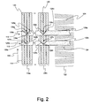
- FIG. 2 is a schematic diagram of an alternative embodiment of a portion of a linear tape drive system
- FIGS. 3 a - 3 c are schematic diagrams, in cross-section, of a substrate undergoing a shadowed deposition process to create a recessed angled sensor;
- FIGS. 4 a - 4 c are schematic diagrams, in cross-section, of a substrate undergoing an anisotropic etching process to create raised angled sensor;
- FIG. 5 a is a schematic diagram, in cross-section, of a read sensor
- FIG. 5 b is a schematic diagram, in cross-section, of a write sensor
- FIG. 5 c is a schematic diagram, in cross-section, of a merged pole sensor.
- FIG. 6 is a schematic diagram of an embodiment of a module with canted servo tracks for a linear tape drive system.
- FIG. 1 is a schematic diagram of a portion of a linear tape drive system.
- the system includes a portion of linear tape drive module 10 and tape 14 having path direction 16 .
- Tape 14 includes data tracks 18 a - 18 n with data transitions 20 at azimuthal orientations relative to path direction 16 .
- the azimuthal orientations shown are +/ ⁇ 45°. Other azimuthal orientations may also be used, e.g.,
- Tape 14 also includes servo track 22 with servo positioning transitions 24 .
- Servo positioning transitions 24 are shown at angles of +/ ⁇ 7°. Other angles may also be used.
- Portion of linear tape drive module 10 includes substrate 26 that provides a tape bearing surface for tape 14 , read sensors 28 a - 28 n constructed on substrate 26 that read data transitions 20 at the azimuthal orientation, and servo sensor 30 oriented substantially perpendicular to path direction 16 that reads servo positioning transitions 24 .
- Servo sensor 30 is disposed in recessed area 32 of substrate 26 .
- Servo sensor 30 is constructed on side wall 34 of recessed area 32 as will be explained in detail below.
- FIG. 2 is a schematic diagram of an alternative embodiment of a linear tape drive system. Numbered elements of FIG. 2 that differ by 100 relative to numbered elements in FIG. 1 have similar descriptions, e.g., 122 and 22 are each servo tracks.
- Substrate 126 a includes recessed areas 136 a - 136 n .
- Read sensors 128 a - 128 n are disposed on side walls 138 a - 138 n of recessed areas 136 a - 136 n respectively.
- Read sensors 128 a - 128 n read data transitions 120 at the azimuthal orientation.
- Substrate 126 b includes recessed areas 137 a - 137 n .
- Read sensors 129 a - 129 n are disposed on side walls 139 a - 139 n of recessed areas 137 a - 137 n respectively.
- Read sensors 129 a - 129 n read data transitions 120 at the azimuthal orientation.
- FIGS. 3 a - 3 c are schematic diagrams, in cross-section, of a substrate undergoing a shadowed deposition process to create a recessed area.
- FIG. 3 a shows substrate 226 and hard windows 240 , e.g., alumina, prior to the shadowed deposition process.
- FIG. 3 b shows substrate 226 and hard windows 240 as material 242 , e.g., CZT, is being deposited.
- material 242 e.g., CZT
- FIG. 3 c shows that once material 242 has been deposited and prepared accordingly, servo sensor 230 may be constructed on side wall 234 of recessed area 232 . Data sensors 228 a and 228 b may also be constructed accordingly.
- FIGS. 4 a - 4 c are schematic diagrams, in cross-section, of a substrate undergoing an anisotropic etching process to create raised features.
- FIG. 4 a shows substrate 326 and material 344 , e.g. AlFeSi, to be anisotropically etched.
- Photoresist portions 346 a , 346 b , and 346 c will facilitate the formation of raised features 344 a , 344 b , and 344 c as described in detail below.
- FIG. 4 b shows raised features 344 a , 344 b , and 344 c after material 344 has been wet etched.
- Raised feature 344 a includes side wall surface 348 a .
- Raised feature 344 b includes side wall 348 b .
- Raised feature 344 c includes side walls 350 .
- FIG. 4 c shows that, once the photoresist portions 346 a , 346 b , and 346 c have been removed, read sensor 328 a may be deposited on surface 352 a of raised feature 344 a and read sensor 328 b may be deposited on surface 352 b of raised feature 344 b .
- read sensor 328 a may be deposited on side wall 348 a of raised feature 344 a and read sensor 328 b may be deposited on side wall 348 b of raised feature 344 b.
- Servo sensor 332 is deposited on one of side walls 350 of raised feature 344 c .
- servo sensor 332 may be deposited on surface 354 of raised feature 344 c.
- FIG. 5 a is a schematic diagram, in cross-section, of read sensor 28 a .
- Read sensor 28 a is constructed on substrate 26 , e.g., AlTiC with insulative cap, and includes bottom shield 56 , e.g., NiFe, AlFeSi, gap alumina 58 , 59 , sensor element 60 , and top shield 62 , e.g., NiFe, CZT.
- FIG. 5 b is a schematic diagram, in cross-section, of write sensor element 63 .
- Write sensor element 63 may be constructed on substrate 26 .
- Write sensor element 63 includes bottom shield 64 , e.g., NiFe, AlFeSi, gap alumina 66 , and top pole 68 , e.g., NiFe, CZT.
- FIG. 5 c is a schematic diagram, in cross-section, of merged pole sensor element 69 .
- Merged pole sensor element 69 may be constructed on substrate 26 .
- Merged pole sensor element 69 includes bottom shield 70 , e.g., NiFe, AlFeSi, read gap alumina 72 , 73 , read sensor element 74 , shared shield 76 , e.g., NiFe, CZT, write gap alumina 78 , and top pole 80 , e.g., NiFe, CZT.
- Read and/or write sensor elements may be constructed in any desired fashion, e.g., piggyback, interleaved.
- FIG. 6 is a schematic diagram of module 410 with canted servo tracks 422 a and 422 b for a linear tape drive system.
- the system includes tape 414 having path direction 416 .
- Tape 414 includes data tracks 418 with data transitions 420 at an azimuthal orientation of
- Other azimuthal orientations may be used, e.g.,
- Servo track 422 a includes servo positioning transitions 424 a at +/ ⁇ 7°.
- Servo track 422 b includes servo positioning transitions 424 b similarly configured to servo positioning transitions 424 a.
- Substrate 426 a provides a tape bearing surface for tape 414 and includes recessed areas 432 a .
- Servo sensors 430 are disposed in recessed areas 432 a and are configured to read servo positioning transitions 424 a and 424 b respectively.
- Merged pole read/write sensors 469 are constructed on substrate 426 a as shown. Merged pole read/write sensors 469 are oriented substantially parallel to data transitions 420 at, for example, ⁇ 45°.
- Closure 427 a e.g., AlTiC, is associated with substrate 426 a.
- Substrate 426 b and its associated servo sensor elements 430 , merged pole read/write sensor elements 469 , and closure 427 b are generally configured as described with reference to substrate 426 a.
- Substrate 426 c and its associated servo sensor elements 430 , merged pole read/write sensor elements 469 , and associated closure 427 c are generally configured as described above but in the complimentary position relative to substrate 426 a.
- Substrate 426 d and its associated servo sensor elements 430 , merged pole read/write sensor elements 469 , and associated closure 427 d are likewise generally configured as described above but shown in the complimentary position relative to substrate 426 b.
- any desired architecture may be used.
- a two module architecture e.g., read/write-write/read for merged pole or piggyback read/write sensor elements may be used.
- This two module architecture would include a first substrate and a first set of one or more read/write sensor elements associated with the first substrate, a closure, a second set of one or more read/write elements, and a second substrate.
- Two module architectures may also use, for example, interleaved read/write sensor elements.
- Three module architectures may also be used. In any of these architectures the servo tracks may be canted or the data tracks may be canted.
Landscapes
- Adjustment Of The Magnetic Head Position Track Following On Tapes (AREA)
Abstract
Description
Claims (20)
Priority Applications (1)
| Application Number | Priority Date | Filing Date | Title |
|---|---|---|---|
| US11/619,330 US7746596B2 (en) | 2007-01-03 | 2007-01-03 | Linear tape drive module for a linear tape drive system |
Applications Claiming Priority (1)
| Application Number | Priority Date | Filing Date | Title |
|---|---|---|---|
| US11/619,330 US7746596B2 (en) | 2007-01-03 | 2007-01-03 | Linear tape drive module for a linear tape drive system |
Publications (2)
| Publication Number | Publication Date |
|---|---|
| US20080158719A1 US20080158719A1 (en) | 2008-07-03 |
| US7746596B2 true US7746596B2 (en) | 2010-06-29 |
Family
ID=39583532
Family Applications (1)
| Application Number | Title | Priority Date | Filing Date |
|---|---|---|---|
| US11/619,330 Active 2029-04-30 US7746596B2 (en) | 2007-01-03 | 2007-01-03 | Linear tape drive module for a linear tape drive system |
Country Status (1)
| Country | Link |
|---|---|
| US (1) | US7746596B2 (en) |
Citations (5)
| Publication number | Priority date | Publication date | Assignee | Title |
|---|---|---|---|---|
| US5523904A (en) * | 1992-06-24 | 1996-06-04 | Quantum Corporation | Linear tape write servo using embedded azimuth servo blocks |
| US6031673A (en) * | 1998-03-04 | 2000-02-29 | Hewlett-Packard Company | Servo band verification in linear tape systems having timing-based servo formats |
| US6700729B1 (en) * | 2000-10-17 | 2004-03-02 | Hewlett-Packard Development Company | Alignment marks for tape head positioning |
| US20040174628A1 (en) * | 2003-03-05 | 2004-09-09 | Schwarz Theodore A. | Large angle azimuth recording and head configurations |
| US7301716B2 (en) * | 2004-02-17 | 2007-11-27 | Advanced Research Corporation | Stepped time based servo pattern and head |
-
2007
- 2007-01-03 US US11/619,330 patent/US7746596B2/en active Active
Patent Citations (6)
| Publication number | Priority date | Publication date | Assignee | Title |
|---|---|---|---|---|
| US5523904A (en) * | 1992-06-24 | 1996-06-04 | Quantum Corporation | Linear tape write servo using embedded azimuth servo blocks |
| US6031673A (en) * | 1998-03-04 | 2000-02-29 | Hewlett-Packard Company | Servo band verification in linear tape systems having timing-based servo formats |
| US6700729B1 (en) * | 2000-10-17 | 2004-03-02 | Hewlett-Packard Development Company | Alignment marks for tape head positioning |
| US20040109257A1 (en) * | 2000-10-17 | 2004-06-10 | Beck Patricia A. | Media with pre-recorded alignment transitions |
| US20040174628A1 (en) * | 2003-03-05 | 2004-09-09 | Schwarz Theodore A. | Large angle azimuth recording and head configurations |
| US7301716B2 (en) * | 2004-02-17 | 2007-11-27 | Advanced Research Corporation | Stepped time based servo pattern and head |
Also Published As
| Publication number | Publication date |
|---|---|
| US20080158719A1 (en) | 2008-07-03 |
Similar Documents
| Publication | Publication Date | Title |
|---|---|---|
| US7551393B2 (en) | Tape recording head with multiple planes of transducer arrays | |
| US9754616B2 (en) | Magnetic head and system having offset arrays | |
| US10199060B2 (en) | Magnetic recording head having longitudinally spaced offset arrays | |
| US9715886B2 (en) | Miniskirt tape head having quasi-statically tilted transducer arrays | |
| US9218838B2 (en) | Quasi-statically tilted head having offset reader/writer transducer pairs | |
| US8797682B1 (en) | Quasi-statically tilted magnetic tape head having backward compatibility | |
| US8810957B1 (en) | Quasi-statically tilted head having dilated transducer pitch | |
| US9129614B2 (en) | Magnetic head having canted arrays | |
| US20140334033A1 (en) | Quasi-statically oriented head for recording non-legacy formats | |
| US9336805B2 (en) | Recording medium having independent track for velocity, timing and/or longitudinal position | |
| US10068590B2 (en) | Method of making magnetically shielded write transducers | |
| US20160196841A1 (en) | Tmr head design with insulative layers for shorting mitigation | |
| US20070030594A1 (en) | Tape recording head with overlapping read transducers | |
| CN103377657A (en) | Module provided with quilted-type coating, data storage system and magnetic recording head | |
| US7746596B2 (en) | Linear tape drive module for a linear tape drive system | |
| US8427780B2 (en) | Planar magnetic writer having offset portions | |
| US9036296B2 (en) | Multiple writers with reduced crosstalk |
Legal Events
| Date | Code | Title | Description |
|---|---|---|---|
| AS | Assignment |
Owner name: SUN MICROSYSTEMS, INC., CALIFORNIA Free format text: ASSIGNMENT OF ASSIGNORS INTEREST;ASSIGNORS:NIBARGER, JOHN P.;DENISON, EDWARD V.;REEL/FRAME:018702/0497 Effective date: 20061218 Owner name: SUN MICROSYSTEMS, INC.,CALIFORNIA Free format text: ASSIGNMENT OF ASSIGNORS INTEREST;ASSIGNORS:NIBARGER, JOHN P.;DENISON, EDWARD V.;REEL/FRAME:018702/0497 Effective date: 20061218 |
|
| STCF | Information on status: patent grant |
Free format text: PATENTED CASE |
|
| FPAY | Fee payment |
Year of fee payment: 4 |
|
| AS | Assignment |
Owner name: ORACLE AMERICA, INC., CALIFORNIA Free format text: MERGER AND CHANGE OF NAME;ASSIGNORS:ORACLE USA, INC.;SUN MICROSYSTEMS, INC.;ORACLE AMERICA, INC.;REEL/FRAME:037306/0292 Effective date: 20100212 |
|
| MAFP | Maintenance fee payment |
Free format text: PAYMENT OF MAINTENANCE FEE, 8TH YEAR, LARGE ENTITY (ORIGINAL EVENT CODE: M1552) Year of fee payment: 8 |
|
| MAFP | Maintenance fee payment |
Free format text: PAYMENT OF MAINTENANCE FEE, 12TH YEAR, LARGE ENTITY (ORIGINAL EVENT CODE: M1553); ENTITY STATUS OF PATENT OWNER: LARGE ENTITY Year of fee payment: 12 |