US7744398B1 - Locking device for an electrical connector - Google Patents
Locking device for an electrical connector Download PDFInfo
- Publication number
- US7744398B1 US7744398B1 US12/362,135 US36213509A US7744398B1 US 7744398 B1 US7744398 B1 US 7744398B1 US 36213509 A US36213509 A US 36213509A US 7744398 B1 US7744398 B1 US 7744398B1
- Authority
- US
- United States
- Prior art keywords
- plug connector
- locking clip
- top wall
- mount header
- catch
- Prior art date
- Legal status (The legal status is an assumption and is not a legal conclusion. Google has not performed a legal analysis and makes no representation as to the accuracy of the status listed.)
- Active
Links
Images


Classifications
-
- H—ELECTRICITY
- H01—ELECTRIC ELEMENTS
- H01R—ELECTRICALLY-CONDUCTIVE CONNECTIONS; STRUCTURAL ASSOCIATIONS OF A PLURALITY OF MUTUALLY-INSULATED ELECTRICAL CONNECTING ELEMENTS; COUPLING DEVICES; CURRENT COLLECTORS
- H01R13/00—Details of coupling devices of the kinds covered by groups H01R12/70 or H01R24/00 - H01R33/00
- H01R13/62—Means for facilitating engagement or disengagement of coupling parts or for holding them in engagement
- H01R13/627—Snap or like fastening
- H01R13/6275—Latching arms not integral with the housing
-
- H—ELECTRICITY
- H01—ELECTRIC ELEMENTS
- H01R—ELECTRICALLY-CONDUCTIVE CONNECTIONS; STRUCTURAL ASSOCIATIONS OF A PLURALITY OF MUTUALLY-INSULATED ELECTRICAL CONNECTING ELEMENTS; COUPLING DEVICES; CURRENT COLLECTORS
- H01R12/00—Structural associations of a plurality of mutually-insulated electrical connecting elements, specially adapted for printed circuits, e.g. printed circuit boards [PCB], flat or ribbon cables, or like generally planar structures, e.g. terminal strips, terminal blocks; Coupling devices specially adapted for printed circuits, flat or ribbon cables, or like generally planar structures; Terminals specially adapted for contact with, or insertion into, printed circuits, flat or ribbon cables, or like generally planar structures
- H01R12/70—Coupling devices
- H01R12/71—Coupling devices for rigid printing circuits or like structures
- H01R12/712—Coupling devices for rigid printing circuits or like structures co-operating with the surface of the printed circuit or with a coupling device exclusively provided on the surface of the printed circuit
- H01R12/716—Coupling device provided on the PCB
- H01R12/718—Contact members provided on the PCB without an insulating housing
-
- H—ELECTRICITY
- H01—ELECTRIC ELEMENTS
- H01R—ELECTRICALLY-CONDUCTIVE CONNECTIONS; STRUCTURAL ASSOCIATIONS OF A PLURALITY OF MUTUALLY-INSULATED ELECTRICAL CONNECTING ELEMENTS; COUPLING DEVICES; CURRENT COLLECTORS
- H01R12/00—Structural associations of a plurality of mutually-insulated electrical connecting elements, specially adapted for printed circuits, e.g. printed circuit boards [PCB], flat or ribbon cables, or like generally planar structures, e.g. terminal strips, terminal blocks; Coupling devices specially adapted for printed circuits, flat or ribbon cables, or like generally planar structures; Terminals specially adapted for contact with, or insertion into, printed circuits, flat or ribbon cables, or like generally planar structures
- H01R12/70—Coupling devices
- H01R12/71—Coupling devices for rigid printing circuits or like structures
- H01R12/72—Coupling devices for rigid printing circuits or like structures coupling with the edge of the rigid printed circuits or like structures
- H01R12/722—Coupling devices for rigid printing circuits or like structures coupling with the edge of the rigid printed circuits or like structures coupling devices mounted on the edge of the printed circuits
- H01R12/724—Coupling devices for rigid printing circuits or like structures coupling with the edge of the rigid printed circuits or like structures coupling devices mounted on the edge of the printed circuits containing contact members forming a right angle
Definitions
- the present invention is generally directed to electronic connectors, and more specifically to securing the connection of a surface-mount header on a printed circuit board with one or more mated plug connectors.
- PCB printed circuit board
- a PCB mounted inside the device housing may have a cable connected to it. This cable may carry power and/or communication signals necessary for the pillow speaker to operate properly. As the pillow speaker nears end of life, or if it needs repair or service, the pillow speaker may need to be opened and the cable disconnected from the PCB.
- a plug connector is commonly used so that the cable can be easily removed from the PCB and easily reconnected to the PCB.
- a plug connector allows an electrical connection to be made without having to attach the cable to the PCB in a way that may potentially damage the PCB.
- One drawback to this method is that the plug connector at the end of the cable can sometimes loosen from mated engagement and become disconnected from the PCB connection header, resulting in device failure or improper operation.
- many PCB connection headers use a “shrouded” connector having a notch that allows the plug connector at the end of the cable to snap into place. This creates a mechanical lock for the mating header and plug connector as well as an electrical connection.
- Prior art locking connector designs typically require the locking device to be part of the PCB connection header. These devices typically do not allow for a low profile locking connection, as the shrouded header is typically high and consumes a lot of space. These devices are generally incompatible with surface-mount technology (SMT) PCB connectors.
- SMT surface-mount technology
- the present invention provides a locking device for securing a surface-mount header and at least one plug connector in mating engagement with one another.
- the locking device may be embodied as a low-profile locking clip that installs on a surface-mount header and secures one or more plug connectors in mating engagement with the surface-mount header. Where more than one plug connector mates with a single surface-mount header, the invention provides a key for ensuring that each plug connector is mated at its proper pin location on the surface-mount header.
- a locking clip of the present invention comprises a top wall including a recess for each plug connector, a rear wall extending downwardly from the top wall, and a pair of laterally spaced side walls extending downwardly from the top wall, each side wall being spaced from the rear wall to define a respective side opening between the side wall and the rear wall.
- the locking clip additionally comprises a plurality of laterally spaced catch members extending downwardly from the top wall and aligned with the pair of side openings, each catch member having an upwardly facing catch surface. The catch surfaces of the plurality of catch members are open in forward and rearward directions and in a direction toward one of the pair of side openings.
- the rear wall engages a rear portion of the surface-mount header to restrict forward displacement of the locking clip
- the pair of side walls engage opposite sides of the plug connector or group of plug connectors to restrict lateral displacement of the locking clip
- the plurality of catch members each engage a corresponding lead pin of the surface-mount header to restrict upward displacement of the locking clip.
- Each recess of the top wall receives a detent tab of a respective plug connector to prevent separation of the at least one plug connector from the surface-mount header.
- the recesses may be laterally spaced to align with the detent tab of a corresponding plug connector only if the plug connector is at the proper pin location on the surface-mount header.
- An undersurface of the top wall may have a beveled portion adjacent a front edge of the top wall to facilitate insertion of a plug connector into mating and locked engagement with the surface mount-header.
- the invention extends to an assembly comprising a locking clip as summarized above in combination with a PCB including a surface-mount header and at least one plug connector mated therewith.
- the invention also covers a method for securing a surface-mount header and a plug connector in mating engagement with one another comprising the steps of (i) installing a locking clip onto the surface-mount header, wherein the locking clip includes at least one catch member engaging a corresponding lead pin of the surface-mount header, and (ii) mating a plug connector with the surface-mount header, wherein the locking clip includes a recess receiving a detent tab of the plug connector.
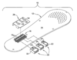
- FIG. 1 is an exploded perspective view of an assembly including a locking clip formed in accordance with a first embodiment of the present invention
- FIG. 2 is an enlarged perspective view of the locking clip shown in FIG. 1 ;
- FIG. 3 is a front elevational view thereof
- FIG. 4 is a side elevational view thereof
- FIG. 5 is a side elevational view of the locking clip installed on a surface-mount header and a plug connector mated with the surface-mount header;
- FIG. 6 is an enlarged perspective view of a locking clip formed in accordance with a second embodiment of the present invention.
- FIG. 7 is a front elevational view of the locking clip shown in FIG. 6 ;
- FIG. 8 is a side elevational view thereof.
- FIG. 9 is a perspective view of the locking clip of the second embodiment installed on a surface-mount header and a plug connector mated with the surface-mount header.
- FIG. 1 shows an assembly 10 that embodies the present invention.
- Assembly 10 comprises a printed circuit board (PCB) 12 having a surface 14 and a surface-mount header 16 by which a cable (not shown) conducting electrical signals may be connected to circuitry on PCB 12 .
- surface-mount header 16 includes a plurality of conductive lead pins 18 soldered to surface 14 of PCB 12 for connection to plug connectors 20 at an end of the cable.
- lead pins 18 may protrude from PCB surface 14 and bend to extend in a direction substantially parallel to PCB surface 14 .
- Each plug connector 20 is configured to mate with surface-mount header 16 to electrically connect individual conductors within the cable to corresponding lead pins 18 .
- the number of lead pins 18 in surface-mount header 16 and number of conductors associated with a given plug connector 20 is subject to variation. As shown, it is possible to have one or more than one plug connector 20 mated with a given surface-mount header 16 .
- surface-mount header 16 is a 24-pin header mating with three different plug connectors 20 , including a 10-pin plug connector (leftmost), an 8-pin plug connector (middle), and a 6-pin plug connector (rightmost).
- surface mount header 16 may be configured and intended to mate with only one plug connector 20 .
- the gender of surface-mount header 16 and plug connector(s) 20 may be interchangeable.
- surface-mount header 16 may have a male configuration and plug connector(s) 20 a mating female configuration, or surface-mount header 16 may have a female configuration and plug connector(s) 20 a mating male configuration.
- Each plug connector 20 includes opposite sides 22 and a detent tab 24 .
- assembly 10 further comprises a locking clip 26 that installs onto surface-mount header 16 and physically retains plug connectors 20 in mating engagement with surface mount-header 16 .
- Locking clip 26 comprises a top wall 28 including one recess 34 for each plug connector 20 , a rear wall 30 extending downwardly from the top wall, and a pair of laterally spaced side walls 32 extending downwardly from the top wall.
- Each side wall 32 may be spaced from rear wall 30 to define respective side openings 40 between side walls 32 and the rear wall 30 (only one side opening being visible in FIG. 2 ).
- each recess 34 is positioned and sized to receive the detent tab 24 of a corresponding plug connector.
- Recess 34 is recessed relative to an undersurface 29 of top wall 28 , and may be embodied as an opening that extends entirely through top wall 28 to allow visual verification that detent tab 24 has been received in the recess.
- Locking clip 26 also includes a plurality of laterally spaced catch members 36 extending downwardly from top wall 28 and aligned with the pair of side openings 40 , whereby catch members 36 are visible in a side view such as FIG. 4 .
- Each catch member 36 has an upwardly facing catch surface 44 that is open in forward and rearward directions and in the same lateral direction toward one of the pair of side openings.
- catch surfaces 44 are open toward the left side of locking clip 26 and closed toward the right side of locking clip 26 by the vertical portion of the catch member.
- catch surfaces 44 are open in forward and rearward directions of locking clip 26 .
- Top wall 28 may include a plurality of through-holes 38 , each through-hole 38 being located overtop a respective one of the plurality of catch surfaces 44 .
- top wall 28 may have a beveled portion 42 adjacent a front edge 31 of the top wall, as best seen in FIGS. 4 and 5 .
- Rear wall 30 may form a slightly obtuse angle “A” with top wall 28 as illustrated in FIG. 4 .
- Locking clip 26 may be economically formed as a molded plastic unit, however other materials and manufacturing methods may be employed without straying from the invention.
- locking clip 26 is installed onto surface-mount header 16 by moving the locking clip forwardly and slightly laterally until each catch member 36 engages a corresponding lead pin 18 and rear wall 30 abuts against a rear portion of surface-mount header 16 where lead pins 18 extend upwardly from solder points on PCB surface 14 .
- each plug connector 20 is mated with surface-mount header 16 at its proper pin location by inserting the plug connector in a rearward direction until its detent tab 24 is received in an aligned recess 34 of locking clip 26 .
- locking clip 26 of the present invention acts as a “key” to ensure proper arrangement of plug connectors 20 .
- rear wall 30 extends from top wall 28 toward PCB surface 14 and engages lead pins 18 at a rear portion of the surface-mount header, thereby restricting forward displacement of locking clip 26 .
- Side walls 32 of locking clip extend from top wall 28 toward board surface 14 to engage opposite sides of the plurality of plug connectors 20 . Where a plurality of plug connectors 20 are arranged side-by-side as shown in FIG. 1 , side walls 32 will engage the exposed side 22 of the leftmost plug connector and the exposed side 22 of the rightmost plug connector to restrict lateral displacement of the locking clip.
- each catch surface 44 is positioned directly under the associated lead wire 18 as shown in FIG. 5 to prevent upwardly directed removal of locking clip 26 .
- top wall 28 may be accomplished manually by reaching into the gap between beveled portion 42 and the top of plug connector 20 with a finger or a tool, for example a screwdriver.
- FIGS. 6-9 show a second embodiment of the present invention, wherein a locking clip 126 is designed for use in securing a single plug connector 20 in mated engagement with a corresponding surface-mount header 16 .
- Locking clip 126 is generally similar to locking clip 26 in its construction and use, however locking clip 126 is narrower side-to-side, has only one recess 34 , and fewer catch members 36 .
- side walls 32 engage opposite sides 22 of single plug connector 20 to restrict lateral displacement of locking clip 126 .
Abstract
Description
-
- 10 Assembly
- 12 Printed circuit board (PCB)
- 14 Surface of PCB
- 16 Surface-mount header
- 18 Lead pins
- 20 Plug connector
- 22 Side of plug connector
- 24 Detent tab of plug connector
- 26 Locking clip
- 28 Top wall of locking clip
- 29 Undersurface of top wall
- 30 Rear wall of locking clip
- 31 Front edge of top wall
- 32 Side wall of locking clip
- 34 Recess
- 36 Catch member
- 38 Through-hole
- 40 Side opening
- 42 Beveled portion of undersurface
- 44 Catch surface of catch member
Claims (14)
Priority Applications (1)
| Application Number | Priority Date | Filing Date | Title |
|---|---|---|---|
| US12/362,135 US7744398B1 (en) | 2009-01-29 | 2009-01-29 | Locking device for an electrical connector |
Applications Claiming Priority (1)
| Application Number | Priority Date | Filing Date | Title |
|---|---|---|---|
| US12/362,135 US7744398B1 (en) | 2009-01-29 | 2009-01-29 | Locking device for an electrical connector |
Publications (1)
| Publication Number | Publication Date |
|---|---|
| US7744398B1 true US7744398B1 (en) | 2010-06-29 |
Family
ID=42271125
Family Applications (1)
| Application Number | Title | Priority Date | Filing Date |
|---|---|---|---|
| US12/362,135 Active US7744398B1 (en) | 2009-01-29 | 2009-01-29 | Locking device for an electrical connector |
Country Status (1)
| Country | Link |
|---|---|
| US (1) | US7744398B1 (en) |
Cited By (3)
| Publication number | Priority date | Publication date | Assignee | Title |
|---|---|---|---|---|
| WO1999046154A1 (en) | 1998-03-10 | 1999-09-16 | Acta Maritime Development Corporation | Container transfer terminal system and method |
| US20180277990A1 (en) * | 2017-03-27 | 2018-09-27 | Molex, Llc | Electrical connection device |
| WO2021231137A1 (en) * | 2020-05-12 | 2021-11-18 | Microsoft Technology Licensing, Llc | Connector bracket for a cable connector |
Citations (4)
| Publication number | Priority date | Publication date | Assignee | Title |
|---|---|---|---|---|
| US4418976A (en) * | 1981-10-16 | 1983-12-06 | Teletype Corporation | Retaining clip for an electrical connector |
| US4509813A (en) * | 1983-11-01 | 1985-04-09 | Allied Corporation | Retaining clip for holding a connector to a panel |
| US5151034A (en) * | 1991-10-07 | 1992-09-29 | Alcatel Network Systems, Inc. | Connector retainer |
| US5316489A (en) * | 1992-10-23 | 1994-05-31 | Molex Incorporated | Surface mount electrical connector |
-
2009
- 2009-01-29 US US12/362,135 patent/US7744398B1/en active Active
Patent Citations (4)
| Publication number | Priority date | Publication date | Assignee | Title |
|---|---|---|---|---|
| US4418976A (en) * | 1981-10-16 | 1983-12-06 | Teletype Corporation | Retaining clip for an electrical connector |
| US4509813A (en) * | 1983-11-01 | 1985-04-09 | Allied Corporation | Retaining clip for holding a connector to a panel |
| US5151034A (en) * | 1991-10-07 | 1992-09-29 | Alcatel Network Systems, Inc. | Connector retainer |
| US5316489A (en) * | 1992-10-23 | 1994-05-31 | Molex Incorporated | Surface mount electrical connector |
Cited By (5)
| Publication number | Priority date | Publication date | Assignee | Title |
|---|---|---|---|---|
| WO1999046154A1 (en) | 1998-03-10 | 1999-09-16 | Acta Maritime Development Corporation | Container transfer terminal system and method |
| US20180277990A1 (en) * | 2017-03-27 | 2018-09-27 | Molex, Llc | Electrical connection device |
| US10170857B2 (en) * | 2017-03-27 | 2019-01-01 | Molex, Llc | Electrical connection device |
| WO2021231137A1 (en) * | 2020-05-12 | 2021-11-18 | Microsoft Technology Licensing, Llc | Connector bracket for a cable connector |
| NL2025563B1 (en) * | 2020-05-12 | 2021-11-30 | Microsoft Technology Licensing Llc | Connector bracket for a cable connector |
Similar Documents
| Publication | Publication Date | Title |
|---|---|---|
| US6210240B1 (en) | Electrical connector with improved terminal | |
| EP2122771B1 (en) | Pluggable screwless wire connector system | |
| EP2610974A2 (en) | Electrical connector | |
| US5772452A (en) | Connector for a circuit board | |
| US8647141B2 (en) | Board-to-board connector assembly | |
| KR101562398B1 (en) | Blade and receptacle power connector | |
| US6767235B2 (en) | Electrical connector having retention system for mounting onto a printed circuit board | |
| KR20090121212A (en) | Stacking connector | |
| US20050287860A1 (en) | Interlocking member for an electrical connector | |
| US20080026608A1 (en) | Connector for Printed Circuit Boards Stacked One On Another | |
| US20080045078A1 (en) | Electrical connector | |
| US9640886B2 (en) | Fitting confirmation construction for connectors | |
| CN100566050C (en) | Board mounted electrical connector assembly | |
| EP1990872A1 (en) | Electric connector assembly | |
| US6808427B1 (en) | Electrical connector with anti-mismating device | |
| TWI323532B (en) | Panel mounted modular jack terminated to a circuit board | |
| CA2099029C (en) | Circuit pack interconnection | |
| US6994595B2 (en) | Finger proof, keyed power connector and methods thereof | |
| EP0729206B1 (en) | PCMCIA input/output card connector | |
| US8851928B2 (en) | Electrical connector | |
| JP2006510169A (en) | Electrical connector with terminal position maintenance system | |
| US7744398B1 (en) | Locking device for an electrical connector | |
| JP5049619B2 (en) | Plug connection adapter | |
| US6884094B1 (en) | Connector with hermaphroditic center ground plane | |
| US9252540B2 (en) | Electrical plug connector having an upstream contact terminal |
Legal Events
| Date | Code | Title | Description |
|---|---|---|---|
| AS | Assignment |
Owner name: CURBELL ELECTRONICS, INC.,NEW YORK Free format text: ASSIGNMENT OF ASSIGNORS INTEREST;ASSIGNORS:WILKOLASKI, EDWARD A.;CAMACHO, CHRISTOPHER P.;SIGNING DATES FROM 20090128 TO 20090129;REEL/FRAME:022189/0318 |
|
| STCF | Information on status: patent grant |
Free format text: PATENTED CASE |
|
| AS | Assignment |
Owner name: CURBELL MEDICAL PRODUCTS, INC., NEW YORK Free format text: CHANGE OF NAME;ASSIGNOR:CURBELL ELECTRONICS, INC.;REEL/FRAME:027795/0746 Effective date: 20120206 |
|
| FPAY | Fee payment |
Year of fee payment: 4 |
|
| MAFP | Maintenance fee payment |
Free format text: PAYMENT OF MAINTENANCE FEE, 8TH YR, SMALL ENTITY (ORIGINAL EVENT CODE: M2552) Year of fee payment: 8 |
|
| MAFP | Maintenance fee payment |
Free format text: PAYMENT OF MAINTENANCE FEE, 12TH YR, SMALL ENTITY (ORIGINAL EVENT CODE: M2553); ENTITY STATUS OF PATENT OWNER: SMALL ENTITY Year of fee payment: 12 |