US7742249B2 - Color wheel - Google Patents
Color wheel Download PDFInfo
- Publication number
- US7742249B2 US7742249B2 US11/829,304 US82930407A US7742249B2 US 7742249 B2 US7742249 B2 US 7742249B2 US 82930407 A US82930407 A US 82930407A US 7742249 B2 US7742249 B2 US 7742249B2
- Authority
- US
- United States
- Prior art keywords
- ring
- ring filter
- fixing
- supporting portion
- color wheel
- Prior art date
- Legal status (The legal status is an assumption and is not a legal conclusion. Google has not performed a legal analysis and makes no representation as to the accuracy of the status listed.)
- Expired - Fee Related, expires
Links
Images


Classifications
-
- G—PHYSICS
- G02—OPTICS
- G02B—OPTICAL ELEMENTS, SYSTEMS OR APPARATUS
- G02B26/00—Optical devices or arrangements for the control of light using movable or deformable optical elements
- G02B26/007—Optical devices or arrangements for the control of light using movable or deformable optical elements the movable or deformable optical element controlling the colour, i.e. a spectral characteristic, of the light
- G02B26/008—Optical devices or arrangements for the control of light using movable or deformable optical elements the movable or deformable optical element controlling the colour, i.e. a spectral characteristic, of the light in the form of devices for effecting sequential colour changes, e.g. colour wheels
-
- G—PHYSICS
- G02—OPTICS
- G02B—OPTICAL ELEMENTS, SYSTEMS OR APPARATUS
- G02B7/00—Mountings, adjusting means, or light-tight connections, for optical elements
- G02B7/006—Filter holders
Definitions
- Taiwan application serial no. 96105014 filed on Feb. 12, 2007. All disclosure of the Taiwan application is incorporated herein by reference.
- the present invention relates to a projector. More particularly, the present invention relates to a color wheel of a projector.
- a digital light processing (DLP) projection device includes an illumination system, a digital micro-mirror device (DMD), and a projection lens.
- the illumination system capable of providing an illuminating light beam, includes a color wheel and a plurality of lenses. After being filtered by the color wheel, the light beam is focused by the lenses and projected onto the DMD.
- the DMD has a plurality of micro-mirrors, which are in ON, OFF, or FLAT states respectively, so as to convert the illuminating light beam into an image light beam.
- the projection lens is used to project the image light beam onto a screen to form an image.
- a conventional color wheel 100 includes a ring filter 110 , a washer 120 , and a motor 130 .
- the ring filter 110 is formed by arranging a plurality of sector sub-filters 112 , and each of the sub-filters 112 is adhered on the motor 130 by dispensing. The joints between the sub-filters 112 are not adhered.
- the washer 120 is located above the ring filter 110 and is adhered to the motor 130 by dispensing.
- the sub-filters 112 are likely to come loose and escape when the motor 130 is rotated at a high speed.
- U.S. Pat. No. 6,504,598 and ROC Patent No. 534329 also provide solutions for the problem that the sub-filters may easily come loose and escape when the motor 130 is rotated at a high speed, but each of the solutions must employ an adhesive to achieve the purpose.
- an adhesive material is coated on the two sides of the filter
- an adhesive of epoxy resin is used to adhere the outer margin of the filter to the inner margin of a circumferential ring. Therefore, the problem that the adhesive is easily deteriorated and carbonized still exists.
- the present invention is directed to provide a color wheel, in which the sub-filters are well secured when the motor is rotated at a high speed.
- one embodiment of the present invention provides a color wheel including a fixing base, a ring filter, a washer and a fixing ring.
- the fixing base has a protrusion portion and a supporting portion.
- the ring filter is fit on the protrusion portion and an inner margin of the ring filter leans on the supporting portion.
- the washer is connected to the protrusion portion, and the ring filter is disposed between the washer and the supporting portion.
- the washer and the supporting portion are capable of clipping the inner margin of the ring filter.
- the fixing ring has an annular supporting portion, a side wall that surrounds the annular supporting portion, and a plurality of fixing blocks connected to the side wall.
- the fixing blocks are dotted on an outer margin of the ring filter.
- the outer margin of the ring filter leans on the annular supporting portion.
- the fixing blocks, the side wall, and the annular supporting portion are capable of clipping the outer margin of the ring filter.
- a color wheel including a fixing base, a ring filter, a washer, and a fixing ring.
- the fixing base has a protrusion portion and a supporting portion.
- the ring filter is fit on the protrusion portion, and an inner margin of the ring filter leans on the supporting portion.
- the washer is connected to the protrusion portion, and the washer and the supporting portion are capable of clipping the inner margin of the ring filter.
- the inner wall of the fixing ring has an annular groove, an outer margin of the ring filter is located in the annular groove, and the two opposite side walls of the annular groove are capable of clipping the outer margin of the ring filter.
- the fixing ring is adopted to clip the ring filter in the present invention, the axial displacement of the ring filter is avoided, and the side wall of the fixing ring secures each sub-filter in the ring filter and thereby reduce the possibility of coming loose and escape due to the centrifugal force when the color wheel is rotated at a high speed. Therefore, the reliability of the color wheel of the present invention is effectively increased.
- the fixing ring is formed by two half-rings, so that it is simple to assemble the color wheel, thus improve the assembly efficiency.
- FIG. 1 is an exploded structural view of a conventional color wheel.
- FIG. 2A is a top view of a color wheel according to a first embodiment of the present invention.
- FIG. 2B is a side view of the color wheel in FIG. 2A .
- FIG. 3 is an exploded view of the color wheel in FIG. 2A .
- FIG. 4 is a schematic sectional view along Line I-I′ in FIG. 2A .
- FIG. 5A is a top view of a fixing base and a washer of a color wheel according a second embodiment of the present invention.
- FIG. 5B is a sectional view along Line J-J′ in FIG. 5A .
- FIG. 5C is a schematic assembly view of the fixing base, the washer, and the ring filter in FIG. 5A .
- FIG. 6 is a sectional view of a color wheel according to another embodiment of the present invention.
- FIGS. 7A and 7B are schematic assembly views of a color wheel according to a third embodiment of the present invention.
- FIG. 8 is a schematic view of another color wheel according to the third embodiment of the present invention.
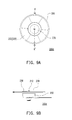
- FIG. 9A is a top view of a color wheel according to a fourth embodiment of the present invention.
- FIG. 9B is a side view of the color wheel in FIG. 9A .
- FIG. 10 is an exploded view of the color wheel in FIG. 9A .
- FIG. 11A is a perspective view of the fixing ring, the washer, and the ring filter in FIG. 9A .
- FIG. 11B is a combination diagram of the fixing ring in FIG. 9A .
- FIG. 11C is a schematic view of assembling the ring filter in FIG. 9A to the fixing ring.
- the description of “A” component facing “B” component herein may contain the situations that “A” component facing “B” component directly or one or more additional components is between “A” component and “B” component.
- the description of “A” component “adjacent to” “B” component herein may contain the situations that “A” component is directly “adjacent to” “B” component or one or more additional components is between “A” component and “B” component. Accordingly, the drawings and descriptions will be regarded as illustrative in nature and not as restrictive.
- a color wheel 200 includes a fixing base 210 , a ring filter 220 , a washer 230 , and a fixing ring 240 .
- the fixing base 210 has a protrusion portion 212 and a supporting portion 214 .
- the ring filter 220 is fit on the protrusion portion 212 , and an inner margin of the ring filter 220 leans on the supporting portion 214 .
- the ring filter 220 is, for example, formed by a plurality of sector sub-filters 222 of different colors. For example, the colors of the sub-filters 222 are red, green, and blue.
- the washer 230 is connected to the protrusion portion 212 , such that the ring filter 220 is disposed between the washer 230 and the supporting portion 214 .
- the washer 230 and the supporting portion 214 clip the inner margin of the ring filter 220 , so as to fix the ring filter 220 onto the fixing base 210 .
- the fixing ring 240 has an annular supporting portion 242 , a side wall 244 that surrounds the annular supporting portion 242 , and a plurality of fixing blocks 246 connected to the side wall 244 .
- the fixing blocks 246 are dotted on an outer margin of the ring filter 220 , for example, dotted on joints 223 of the outer margins of the sub-filters 222 .
- One end of each fixing block 246 is connected to the side wall 244 , and the other end is pressed on the joint 223 of two adjacent sub-filters 222 .
- the outer margin of the ring filter 220 leans on the annular supporting portion 242 .
- the fixing blocks 246 , the annular supporting portion 242 , and the side wall 244 are capable of clipping the outer margin of the ring filter 220 , so as to fix the ring filter 220 onto the fixing ring 240 .
- the fixing blocks 246 avoid axial displacement along a Y-axis of the ring filter 220 , and fix the joints 223 of the ring filter 220 , thus preventing the sub-filters 222 being separated from each other, such that no gap is generated to cause light leakage.
- the side wall 244 avoids axial displacement along an X-axis of the ring filter, so as to prevent the sub-filters 222 in the ring filter 220 from departing due to the centrifugal force when the color wheel 200 is rotated at a high speed.
- the dotted fixing blocks 246 , the annular supporting portion 242 , and the side wall 244 are used to clip the ring filter 220 , so the ring filter 220 is properly secured and the possibility of coming loose due to the centrifugal force when the color wheel 200 is rotated at a high speed is effectively reduced, and no axial displacement along the Y-axis occurs. Moreover, the color wheel 200 has a simple structure and the material cost is thus reduced. Further, in this embodiment, it is not necessary to adhere the sub-filters 222 of the ring filter 220 onto the fixing base 210 or the joints 223 with a large amount of adhesive, so the deterioration of the adhesive caused by high temperature is prevented, thus the reliability of the color wheel 200 is effectively increased.
- the color wheel 200 further includes a motor 250 , the supporting portion 214 of the fixing base 210 is, for example, a surface of a rotating disk of the motor 250 , and the protrusion portion 212 is, for example, a rotating shaft of the motor 250 .
- the fixing base 210 is also a component independent from the motor 250 , the motor 250 has a rotating disk (not shown), and the fixing base 210 is firmly connected to the rotating disk, such that the fixing base 210 is driven to rotate through the rotation of the rotating disk, and this embodiment is not limited herein.
- a buffer member is used to fill the gap, such that the ring filter 220 , the side wall 244 , and the protrusion portion 212 are securely joined, thereby reducing the possibility of damage caused by the collision between the ring filter 220 , the protrusion portion 212 , and the side wall 244 .
- the material of the buffer member is, for example, but not limited to, rubber or silica gel.
- each sub-filter 222 is leant on the supporting portion 214
- the outer margin of the ring filter 220 is leant on the annular supporting portion 242 .
- the fixing blocks 246 are fixed on the side wall 244 and the ring filter 220 .
- the washer 230 is connected to the protrusion portion 212 .
- the washer 230 and the protrusion portion 212 are connected by means of screw locking, integral formation, or snapping, and so on.
- screw locking scheme referring to FIG. 3 , the washer 230 has a tapped hole 231 , and the protrusion portion 212 has an external thread for being screwed with the tapped hole 231 , so as to connect the washer 230 to the protrusion portion 212 .
- the fixing base 210 a and the washer 230 a are integrally formed or not, and the fixing base 210 a is a component of the motor or a component independent from the motor.
- the fixing base 210 a and the washer 230 a are integrally formed.
- the protrusion portion 212 a of the fixing base 210 a has a center hole 213 a
- the washer 230 a has a center hole 231 a communicating with the center hole 213 a
- the center holes 213 a , 231 a are connected to a rotating shaft (not shown) of the motor.
- An accommodation space 215 a is formed between the washer 230 a , the protrusion portion 212 a , and the supporting portion 214 a , and the inner margin of each sub-filter 222 of the ring filter 220 is disposed in the accommodation space 215 a by inserting, so as to form a ring filter.
- the fixing base 210 a and the washer 230 a are independent components respectively.
- the difference between the fixing base 210 a and the washer 230 a integrally formed or not is the joint place of the fixing base 210 a and the washer 230 a .
- the difference is illustrated in detail below, and the similarities thereof will not be described herein again.
- a top surface 216 a of the protrusion portion 212 a of the fixing base 210 a is pressed by a bottom surface 232 a of the washer 230 a for forming an accommodation space 215 a between the washer 230 a , the protrusion portion 212 a , and the supporting portion 214 a , and the inner margin of the ring filter 222 is disposed in the accommodation space 215 a .
- the snapping scheme referring to FIG.
- the washer 230 b and the fixing base 210 are separate components, in which the fixing base 210 is a component of the motor or a component independent from the motor.
- the fixing base 210 b includes a supporting portion 214 b and a protrusion portion 212 b .
- the top of the protrusion portion 212 b has at least two hooks 216 , and a notch 217 exists between the hooks 216 , in which the notch 217 is suitable for accommodating the deformed hooks 216 .
- the washer 230 b has a center hole 231 b .
- the ring filter 220 Upon assembling, the ring filter 220 is first disposed on the fixing base 210 b , and then the center hole 231 b penetrates the protrusion portion 212 b by the elastic deformation of the hooks 216 , such that the washer 230 b is fit on the protrusion portion 212 b . At this time, the hooks 216 are pressed on the washer 230 b , and thus the washer 230 b and the ring filter 220 are fixed on the fixing base 210 b . It should be noted that, in the present invention, the connection of the washer to the fixing base is not limited.
- the fixing blocks 246 are fixed onto the side wall 244 and the ring filter 220 by means of adhesion, bending, welding, or fusion, and so on.
- the fixing blocks are a plurality of adhesives, such as solid adhesives or ultraviolet curing adhesives.
- the adhesives are dotted on the joints 223 of the sub-filters 222 , so as to fix by the adhesiveness of the adhesives.
- the fixing blocks 246 c , the side wall 244 c , and the annular supporting portion 242 c are integrally formed, and the material thereof is, for example, aluminum or other metals.
- the side wall 244 c and the annular supporting porting 242 c are formed first, and then, a portion of the side wall 244 c is bent towards the ring filter 220 until being pressed on the joint 223 of two adjacent sub-filters 222 , so as to form the fixing blocks 246 c (as shown in FIG. 7B ). While in welding scheme, referring to FIG. 8 , the fixing blocks 246 c , the side wall 244 c , and the annular supporting portion 242 c are formed by the same material (for example, metal or plastic), and the side wall 244 c and the annular supporting portion 242 c are integrally formed.
- the granular fixing blocks 246 c are first dotted on the joints 223 of the sub-filters 222 , and then connected to the side wall 244 c by welding or fusion, in which the fixing blocks 246 c made of metal are fixed by welding, while the fixing blocks 246 c made of plastic are fixed by fusion.
- the difference between a color wheel 200 d of a second embodiment of the present invention and the color wheel 200 of the first embodiment lies in the fixing ring.
- identical components are represented by the same symbols.
- the difference between the two embodiments is illustrated in detail below, and the similarities thereof will not be described herein again.
- the inner wall of the fixing ring 300 of the color wheel 200 d has an annular groove 302
- the outer margin of the ring filter 220 is located in the annular groove 302
- the two opposite side walls of the annular groove 302 are capable of clipping the outer margin of the ring filter 220 .
- the annular groove 302 avoids axial displacement of the ring filter 220 , so as to secure the ring filter 220 and reduce the possibility of coming loose due to the centrifugal force when the color wheel 200 is rotated at a high speed.
- the fixing ring 300 includes a first half-ring 310 , a second half-ring 320 connected to the first half-ring 310 , and two fixing members 330 .
- Each of two ends of the first half-ring 310 has a first joint portion 312
- each of two ends of the second half-ring 320 has a second joint portion 322
- each of the first joint portions 312 is joined with one of the second joint portions 322 .
- Each of the first joint portions 312 has a first through hole 312 a
- each of the second joint portions 322 has a second through hole 322 a
- each of the fixing members 330 penetrates the first through hole 312 a and the second through hole 322 a of each joined first and second joint portions 312 , 322 .
- the first half-ring 310 and the second half-ring 320 are fixed with the fixing members 330 after the alignment of the first half-ring 310 and the second half-ring 320 .
- a fixing member 330 penetrates the first through hole 312 a of one of the first joint portions 312 and the second through hole 322 a of the corresponding second joint portion 322 , so as to form a pivot (as shown in FIG. 11B ).
- the subsequent assembly is completed merely by fixing another first joint portion 312 to the corresponding second joint portion 322 with the fixing member 330 .
- the fixing members 330 are, for example, fasteners, which penetrate the first through holes 312 a and the second through holes 322 a to fix the first half-ring 310 and the second half-ring 320 .
- the fixing members are also screws, and the inner sides of the first through holes 312 a and the second through holes 322 a have threads, such that the fixing members 330 are locked in the first through holes 312 a and the second through holes 322 a .
- an adhesive is applied to the joints of the first half-ring 310 and the second half-ring 320 , so as to adhere the first half-ring 310 and the second half-ring 320 .
- the color wheel 200 d further includes a buffer member disposed between the outer margin of the ring filter 220 and the bottom of the annular groove 302 , used for tightly clipping the ring filter 220 so that the possibility of damage to the ring filter 220 caused by collision is effectively reduced.
- the buffer member is made of, for example, but not limited to, rubber or silica gel.
- the fixing ring 300 is formed by the first half-ring 310 and the second half-ring 320 , it is easy to assemble the color wheel 200 d , thereby improving the assembly efficiency.
- the color wheel of the present invention at least has the following advantages:
- the buffer member makes the ring filter, the fixing base, and the fixing ring securely joined.
- the fixing ring can be formed by two half-rings, so it is easy to assemble the color wheel, and the assembly efficiency is thus improved.
- the term “the invention”, “the present invention” or the like is not necessary limited the claim scope to a specific embodiment, and the reference to particularly preferred exemplary embodiments of the invention does not imply a limitation on the invention, and no such limitation is to be inferred.
- the invention is limited only by the spirit and scope of the appended claims.
- the abstract of the disclosure is provided to comply with the rules requiring an abstract, which will allow a searcher to quickly ascertain the subject matter of the technical disclosure of any patent issued from this disclosure. It is submitted with the understanding that it will not be used to interpret or limit the scope or meaning of the claims. Any advantages and benefits described may not apply to all embodiments of the invention.
Landscapes
- Physics & Mathematics (AREA)
- Astronomy & Astrophysics (AREA)
- Spectroscopy & Molecular Physics (AREA)
- General Physics & Mathematics (AREA)
- Optics & Photonics (AREA)
- Optical Filters (AREA)
- Projection Apparatus (AREA)
Abstract
Description
Claims (14)
Applications Claiming Priority (3)
| Application Number | Priority Date | Filing Date | Title |
|---|---|---|---|
| TW096105014A TW200834220A (en) | 2007-02-12 | 2007-02-12 | Color wheel |
| TW96105014A | 2007-02-12 | ||
| TW96105014 | 2007-02-12 |
Publications (2)
| Publication Number | Publication Date |
|---|---|
| US20080192372A1 US20080192372A1 (en) | 2008-08-14 |
| US7742249B2 true US7742249B2 (en) | 2010-06-22 |
Family
ID=39685583
Family Applications (1)
| Application Number | Title | Priority Date | Filing Date |
|---|---|---|---|
| US11/829,304 Expired - Fee Related US7742249B2 (en) | 2007-02-12 | 2007-07-27 | Color wheel |
Country Status (2)
| Country | Link |
|---|---|
| US (1) | US7742249B2 (en) |
| TW (1) | TW200834220A (en) |
Cited By (2)
| Publication number | Priority date | Publication date | Assignee | Title |
|---|---|---|---|---|
| US20150263594A1 (en) * | 2014-03-17 | 2015-09-17 | Alstom Technology Ltd | Tool and a method for the assembly of a generator |
| US20190170331A1 (en) * | 2015-06-12 | 2019-06-06 | Materion Corporation | Optical converter colour wheel |
Families Citing this family (3)
| Publication number | Priority date | Publication date | Assignee | Title |
|---|---|---|---|---|
| CN102854729B (en) * | 2012-02-26 | 2014-03-19 | 深圳市光峰光电技术有限公司 | Light-emitting device, light-emitting device assembly and related projection system |
| JP6863125B2 (en) * | 2017-06-22 | 2021-04-21 | カシオ計算機株式会社 | Fluorescent wheel |
| CN214846204U (en) * | 2021-06-24 | 2021-11-23 | 中强光电股份有限公司 | Wavelength conversion element and projection device |
Citations (5)
| Publication number | Priority date | Publication date | Assignee | Title |
|---|---|---|---|---|
| US6504598B2 (en) | 1998-04-10 | 2003-01-07 | Minolta Co., Ltd. | Illumination device |
| US6914734B1 (en) * | 2003-12-15 | 2005-07-05 | Asia Optical Co., Inc | Color wheel and color filter assembly thereof |
| US20060087756A1 (en) * | 2004-10-26 | 2006-04-27 | Ching-Hsiang Yu | Color wheel |
| US7180691B2 (en) * | 2005-04-22 | 2007-02-20 | Asia Optical Co., Inc. | Color wheel assembly |
| US7295392B2 (en) * | 2005-04-22 | 2007-11-13 | Oc Oerlikon Balzers Ag | Color wheel with aligned segments |
-
2007
- 2007-02-12 TW TW096105014A patent/TW200834220A/en unknown
- 2007-07-27 US US11/829,304 patent/US7742249B2/en not_active Expired - Fee Related
Patent Citations (5)
| Publication number | Priority date | Publication date | Assignee | Title |
|---|---|---|---|---|
| US6504598B2 (en) | 1998-04-10 | 2003-01-07 | Minolta Co., Ltd. | Illumination device |
| US6914734B1 (en) * | 2003-12-15 | 2005-07-05 | Asia Optical Co., Inc | Color wheel and color filter assembly thereof |
| US20060087756A1 (en) * | 2004-10-26 | 2006-04-27 | Ching-Hsiang Yu | Color wheel |
| US7180691B2 (en) * | 2005-04-22 | 2007-02-20 | Asia Optical Co., Inc. | Color wheel assembly |
| US7295392B2 (en) * | 2005-04-22 | 2007-11-13 | Oc Oerlikon Balzers Ag | Color wheel with aligned segments |
Cited By (4)
| Publication number | Priority date | Publication date | Assignee | Title |
|---|---|---|---|---|
| US20150263594A1 (en) * | 2014-03-17 | 2015-09-17 | Alstom Technology Ltd | Tool and a method for the assembly of a generator |
| US9876415B2 (en) * | 2014-03-17 | 2018-01-23 | Alstom Technology Ltd | Tool and a method for the assembly of a generator |
| US20190170331A1 (en) * | 2015-06-12 | 2019-06-06 | Materion Corporation | Optical converter colour wheel |
| US10473299B2 (en) * | 2015-06-12 | 2019-11-12 | Materion Corporation | Optical converter colour wheel |
Also Published As
| Publication number | Publication date |
|---|---|
| TW200834220A (en) | 2008-08-16 |
| US20080192372A1 (en) | 2008-08-14 |
Similar Documents
| Publication | Publication Date | Title |
|---|---|---|
| US7004604B2 (en) | Sequential color display device including light shading means | |
| US7742249B2 (en) | Color wheel | |
| JP6669514B2 (en) | Lens unit | |
| US7901090B2 (en) | Adjustable reflective mirror module and projection apparatus using the same | |
| US9081266B2 (en) | Light source module and projection device using the same | |
| US7175283B2 (en) | Optical device, optical device manufacturing method, and projector | |
| US20060066817A1 (en) | Color wheel | |
| WO2014192794A1 (en) | Image display element holding mechanism, prism unit, and projector | |
| JP2013064347A (en) | Centrifugal fan and projector | |
| US20200264445A1 (en) | Optical device | |
| US11048059B2 (en) | Optical module and projection apparatus | |
| US20070229996A1 (en) | Color wheel and assembly method thereof | |
| US20090079947A1 (en) | Light source assembly and projector having same | |
| US20190353992A1 (en) | Optical component | |
| JP4873234B2 (en) | Color wheel unit and projector | |
| US20060132720A1 (en) | Color wheel unit and optical engine having the same | |
| US7916376B2 (en) | Projection system and optical actuator thereof | |
| JP2006162651A (en) | Color wheel apparatus and projector apparatus | |
| CN211402883U (en) | Novel lens assembly and projector | |
| US20210247670A1 (en) | Adjustable optical module and projector | |
| US20070053089A1 (en) | Color wheel | |
| CN111045177A (en) | A new type of lens assembly and projector | |
| JP2006064785A (en) | Single plate type color wheel system | |
| US20090147159A1 (en) | Projector | |
| JP2009053593A (en) | Color wheel unit and projector |
Legal Events
| Date | Code | Title | Description |
|---|---|---|---|
| AS | Assignment |
Owner name: YOUNG OPTICS INC., TAIWAN Free format text: ASSIGNMENT OF ASSIGNORS INTEREST;ASSIGNORS:LIN, KUO-CHIANG;LIN, HSIN-CHUNG;CHUANG, FU-MING;REEL/FRAME:019635/0653 Effective date: 20070701 Owner name: YOUNG OPTICS INC.,TAIWAN Free format text: ASSIGNMENT OF ASSIGNORS INTEREST;ASSIGNORS:LIN, KUO-CHIANG;LIN, HSIN-CHUNG;CHUANG, FU-MING;REEL/FRAME:019635/0653 Effective date: 20070701 |
|
| STCF | Information on status: patent grant |
Free format text: PATENTED CASE |
|
| FPAY | Fee payment |
Year of fee payment: 4 |
|
| MAFP | Maintenance fee payment |
Free format text: PAYMENT OF MAINTENANCE FEE, 8TH YEAR, LARGE ENTITY (ORIGINAL EVENT CODE: M1552) Year of fee payment: 8 |
|
| FEPP | Fee payment procedure |
Free format text: MAINTENANCE FEE REMINDER MAILED (ORIGINAL EVENT CODE: REM.); ENTITY STATUS OF PATENT OWNER: LARGE ENTITY |
|
| LAPS | Lapse for failure to pay maintenance fees |
Free format text: PATENT EXPIRED FOR FAILURE TO PAY MAINTENANCE FEES (ORIGINAL EVENT CODE: EXP.); ENTITY STATUS OF PATENT OWNER: LARGE ENTITY |
|
| STCH | Information on status: patent discontinuation |
Free format text: PATENT EXPIRED DUE TO NONPAYMENT OF MAINTENANCE FEES UNDER 37 CFR 1.362 |
|
| FP | Lapsed due to failure to pay maintenance fee |
Effective date: 20220622 |