US7741739B2 - Automotive alternator - Google Patents
Automotive alternator Download PDFInfo
- Publication number
- US7741739B2 US7741739B2 US11/604,687 US60468706A US7741739B2 US 7741739 B2 US7741739 B2 US 7741739B2 US 60468706 A US60468706 A US 60468706A US 7741739 B2 US7741739 B2 US 7741739B2
- Authority
- US
- United States
- Prior art keywords
- voltage regulator
- fins
- heatsink
- cooling airflow
- disposed
- Prior art date
- Legal status (The legal status is an assumption and is not a legal conclusion. Google has not performed a legal analysis and makes no representation as to the accuracy of the status listed.)
- Expired - Fee Related
Links
Images


Classifications
-
- H—ELECTRICITY
- H05—ELECTRIC TECHNIQUES NOT OTHERWISE PROVIDED FOR
- H05K—PRINTED CIRCUITS; CASINGS OR CONSTRUCTIONAL DETAILS OF ELECTRIC APPARATUS; MANUFACTURE OF ASSEMBLAGES OF ELECTRICAL COMPONENTS
- H05K7/00—Constructional details common to different types of electric apparatus
- H05K7/20—Modifications to facilitate cooling, ventilating, or heating
- H05K7/2089—Modifications to facilitate cooling, ventilating, or heating for power electronics, e.g. for inverters for controlling motor
- H05K7/20909—Forced ventilation, e.g. on heat dissipaters coupled to components
- H05K7/20918—Forced ventilation, e.g. on heat dissipaters coupled to components the components being isolated from air flow, e.g. hollow heat sinks, wind tunnels or funnels
-
- H—ELECTRICITY
- H02—GENERATION; CONVERSION OR DISTRIBUTION OF ELECTRIC POWER
- H02K—DYNAMO-ELECTRIC MACHINES
- H02K5/00—Casings; Enclosures; Supports
- H02K5/04—Casings or enclosures characterised by the shape, form or construction thereof
- H02K5/22—Auxiliary parts of casings not covered by groups H02K5/06-H02K5/20, e.g. shaped to form connection boxes or terminal boxes
- H02K5/225—Terminal boxes or connection arrangements
-
- H—ELECTRICITY
- H02—GENERATION; CONVERSION OR DISTRIBUTION OF ELECTRIC POWER
- H02K—DYNAMO-ELECTRIC MACHINES
- H02K11/00—Structural association of dynamo-electric machines with electric components or with devices for shielding, monitoring or protection
- H02K11/04—Structural association of dynamo-electric machines with electric components or with devices for shielding, monitoring or protection for rectification
- H02K11/049—Rectifiers associated with stationary parts, e.g. stator cores
-
- H—ELECTRICITY
- H02—GENERATION; CONVERSION OR DISTRIBUTION OF ELECTRIC POWER
- H02K—DYNAMO-ELECTRIC MACHINES
- H02K5/00—Casings; Enclosures; Supports
- H02K5/04—Casings or enclosures characterised by the shape, form or construction thereof
- H02K5/14—Means for supporting or protecting brushes or brush holders
- H02K5/141—Means for supporting or protecting brushes or brush holders for cooperation with slip-rings
-
- H—ELECTRICITY
- H02—GENERATION; CONVERSION OR DISTRIBUTION OF ELECTRIC POWER
- H02K—DYNAMO-ELECTRIC MACHINES
- H02K5/00—Casings; Enclosures; Supports
- H02K5/04—Casings or enclosures characterised by the shape, form or construction thereof
- H02K5/20—Casings or enclosures characterised by the shape, form or construction thereof with channels or ducts for flow of cooling medium
- H02K5/207—Casings or enclosures characterised by the shape, form or construction thereof with channels or ducts for flow of cooling medium with openings in the casing specially adapted for ambient air
-
- H—ELECTRICITY
- H02—GENERATION; CONVERSION OR DISTRIBUTION OF ELECTRIC POWER
- H02K—DYNAMO-ELECTRIC MACHINES
- H02K9/00—Arrangements for cooling or ventilating
- H02K9/02—Arrangements for cooling or ventilating by ambient air flowing through the machine
- H02K9/04—Arrangements for cooling or ventilating by ambient air flowing through the machine having means for generating a flow of cooling medium
- H02K9/06—Arrangements for cooling or ventilating by ambient air flowing through the machine having means for generating a flow of cooling medium with fans or impellers driven by the machine shaft
-
- H—ELECTRICITY
- H02—GENERATION; CONVERSION OR DISTRIBUTION OF ELECTRIC POWER
- H02K—DYNAMO-ELECTRIC MACHINES
- H02K9/00—Arrangements for cooling or ventilating
- H02K9/28—Cooling of commutators, slip-rings or brushes e.g. by ventilating
-
- H—ELECTRICITY
- H05—ELECTRIC TECHNIQUES NOT OTHERWISE PROVIDED FOR
- H05K—PRINTED CIRCUITS; CASINGS OR CONSTRUCTIONAL DETAILS OF ELECTRIC APPARATUS; MANUFACTURE OF ASSEMBLAGES OF ELECTRICAL COMPONENTS
- H05K7/00—Constructional details common to different types of electric apparatus
- H05K7/20—Modifications to facilitate cooling, ventilating, or heating
- H05K7/2089—Modifications to facilitate cooling, ventilating, or heating for power electronics, e.g. for inverters for controlling motor
- H05K7/209—Heat transfer by conduction from internal heat source to heat radiating structure
-
- H—ELECTRICITY
- H02—GENERATION; CONVERSION OR DISTRIBUTION OF ELECTRIC POWER
- H02K—DYNAMO-ELECTRIC MACHINES
- H02K2205/00—Specific aspects not provided for in the other groups of this subclass relating to casings, enclosures, supports
- H02K2205/09—Machines characterised by drain passages or by venting, breathing or pressure compensating means
-
- H—ELECTRICITY
- H02—GENERATION; CONVERSION OR DISTRIBUTION OF ELECTRIC POWER
- H02K—DYNAMO-ELECTRIC MACHINES
- H02K7/00—Arrangements for handling mechanical energy structurally associated with dynamo-electric machines, e.g. structural association with mechanical driving motors or auxiliary dynamo-electric machines
- H02K7/18—Structural association of electric generators with mechanical driving motors, e.g. with turbines
- H02K7/1807—Rotary generators
- H02K7/1815—Rotary generators structurally associated with reciprocating piston engines
Definitions
- the present invention relates to an automotive alternator that is mounted to a vehicle, and particularly relates to a construction that cools a voltage regulator.
- a rectifier assembly is configured into an approximate C shape, and a voltage regulator, a brush holder, and a connector are configured integrally into a regulator assembly.
- the voltage regulator and the brush holder are disposed so as to overlap in an axial direction of a shaft, and the connector is disposed at a position that is rotated by a predetermined angle circumferentially from the voltage regulator and the brush holder in a plane that is perpendicular to the shaft and that includes the voltage regulator and the brush holder such that an opening portion faces radially outward.
- the regulator assembly is disposed in a space in an opening portion of the C shape of the rectifier assembly.
- ventilation resistance in the connector and ventilation resistance in the voltage regulator differ from each other, and irregularities in ventilation resistance on an intake side that includes the rectifier assembly are great.
- improved conventional automotive alternators include a regulator assembly in which a voltage regulator and a brush holder are disposed so as to overlap in an axial direction of a shaft, and the connector is disposed in close contact with the voltage regulator radially outside the voltage regulator such that an opening portion faces radially outward (see Patent Literature 1, for example).
- the regulator assembly is disposed in a space in an opening portion of the rectifier assembly that has a C shape, the heatsink of the rectifier can be made larger, improving cooling of the rectifier.
- irregularities in ventilation resistance on the air intake side that includes the rectifier assembly are reduced.
- Patent Literature 1 Japanese Patent Laid-Open No. 2002-142423 (Gazette), which corresponds to U.S. Pat. No. 6,740,995 to Oohashi et al.
- the connector is disposed radially outside the voltage regulator in order to improve cooling of the rectifier.
- the heatsink of the voltage regulator is disposed in a plane that is perpendicular to the shaft such that ventilation channels between the fins are aligned in a radial direction.
- the connector is placed in close contact with a radially outer side surface of the heatsink of the voltage regulator, and is in a state that blocks radially outer openings of the ventilation channels between the fins.
- the present invention aims to solve the above problems and an object of the present invention is to provide an automotive alternator that enables performance to be increased by suppressing deterioration of cooling of a voltage regulator that results from improvements in cooling of a rectifier to suppress temperature increases in the rectifier and the voltage regulator.
- an automotive alternator including: a case; a shaft that is rotatably supported by the case; a rotor that is accommodated inside the case and that has: a pole core that is fixed to the shaft; a field winding that is mounted to the pole core; and at least one centrifugal fan that is fixed to an axial end of the pole core; a stator that is fixed to the case so as to surround the rotor; a voltage regulator that adjusts magnitude of an alternating voltage that is generated in the stator; a voltage regulator heatsink that is disposed on an opposite side of the voltage regulator from the centrifugal fan; and a connector that is disposed on an outer circumferential side of the voltage regulator and to which an external plug can be mounted.
- a plurality of air intake apertures are formed on a side of the case that faces the centrifugal fan and a plurality of fins are arrayed circumferentially on a side of the voltage regulator heatsink that faces the case.
- the automotive alternator is characterized in that a cooling airflow introducing guide portion is disposed on a portion of the connector that faces the voltage regulator heatsink.
- the connector is positioned on an outer circumferential side of the voltage regulator, installation regions for the rectifier and the rectifier heatsink are enlarged, suppressing temperature increases in the rectifier.
- Cooling airflow that has flowed in through the air intake apertures enters the ventilation channels between the fins of the voltage regulator heatsink. A portion of the cooling airflow flows radially inward through the ventilation channels. A remaining portion of the cooling airflow flows radially outward through the ventilation channels, and then flows circumferentially between the fins and the cooling airflow introducing guide portion.
- the cooling airflow flows through the entire radial length of the ventilation channels between the fins and absorbs heat generated in the voltage regulator efficiently, temperature increases in the voltage regulator can be suppressed.
- FIG. 1 is a view from a rear end of an automotive alternator according to a preferred embodiment of the present invention
- FIG. 2 is a cross section of part of the automotive alternator according to the preferred embodiment of the present invention.
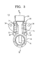
- FIG. 3 is a front elevation of a regulator assembly that can be used in the automotive alternator according to the preferred embodiment of the present invention
- FIG. 4 is a cross section taken along line IV-IV in FIG. 3 viewed from the direction of the arrows;
- FIG. 5 is a view of the regulator assembly that can be used in the automotive alternator according to the preferred embodiment of the present invention from a side near a connector opening portion;
- FIG. 6 is a partial perspective for explaining cooling airflows in the automotive alternator according to the preferred embodiment of the present invention.
- FIG. 7 is a partial perspective for explaining the cooling airflows in the automotive alternator according to the preferred embodiment of the present invention.
- FIG. 8 is a partial perspective that shows a vicinity of an air intake aperture in an automotive alternator according to one variation of the present invention.
- FIGS. 9A and 9B are a partial perspective view and a side view, respectively, that explain cooling airflows in the automotive alternator according to one variation of the present invention.
- FIG. 10 is a partial perspective that shows a vicinity of an air intake aperture in an automotive alternator that functions as a comparative example.
- FIGS. 11A and 11B are a partial perspective view and a side view, respectively, that explain cooling airflows in the automotive alternator that functions as a comparative example.
- FIG. 1 is a view from a rear end of an automotive alternator according to a preferred embodiment of the present invention
- FIG. 2 is a cross section of part of the automotive alternator according to the preferred embodiment of the present invention
- FIG. 3 is a front elevation of a regulator assembly that can be used in the automotive alternator according to the preferred embodiment of the present invention
- FIG. 4 is a cross section taken along line IV-IV in FIG. 3 viewed from the direction of the arrows
- FIG. 5 is a view of the regulator assembly that can be used in the automotive alternator according to the preferred embodiment of the present invention from a side near a connector opening portion
- FIGS. 6 and 7 are each partial perspectives for explaining cooling airflows in the automotive alternator according to the preferred embodiment of the present invention.
- an automotive alternator includes: a case 1 that is constituted by a front bracket (not shown) and a rear bracket 2 that are each approximately bowl-shaped and made of aluminum; a shaft 3 that is rotatably supported by the case 1 ; a rotor 4 that is fixed to the shaft 3 so as to be rotatably disposed inside the case 1 ; centrifugal fans 7 that are fixed to two axial end surfaces of the rotor 4 ; a stator 8 that is held by the case 1 so as to surround the rotor 4 ; a pair of slip rings 11 that are fixed to a rear-end end portion of the shaft 3 so as to supply field current to the rotor 4 ; a rectifier (not shown) that is electrically connected to the stator 8 so as to rectify alternating current that is generated in the stator 8 into direct current; and a regulator assembly 13 .
- the rotor 4 includes: a rotor coil 5 functioning as a field winding that generates magnetic flux on passage of electric current; and a pole core 6 that is disposed so as to cover the rotor coil 5 such that magnetic poles are formed by the magnetic flux.
- the stator 8 includes: a stator core 9 ; a stator coil 10 that is installed in the stator core 9 such that alternating current arises due to changes in the magnetic flux from the rotor coil 5 accompanying rotation of the rotor 4 .
- This stator 8 is disposed so as to surround the rotor 4 , and is mounted such that outer circumferential edge portions of two axial end surfaces of the stator core 9 are held under pressure by the front bracket and the rear bracket 2 , which are fastened using fastening bolts 12 .
- the regulator assembly 13 includes: a ring-shaped slinger 14 through which the shaft 3 is inserted; a brush holder 15 that is disposed so as to extend radially outward from an outer circumferential wall surface of the slinger 14 and that is formed such that a brush insertion aperture 15 a that has an aperture direction in a radial direction is open at an inner circumferential wall surface of the slinger 14 ; a pair of brushes 16 that are inserted inside the brush insertion aperture 15 a so as to line up in an axial direction of the slinger 14 and be movable radially; springs 17 that are disposed inside the brush insertion aperture 15 a so as to force the pair of brushes 16 toward the slinger 14 ; a voltage regulator 18 that is disposed on a first side of the brush holder 15 in an axial direction of the slinger 14 and that adjusts magnitude of an alternating voltage that is generated in the stator 8 ; and a connector 20 to which an external plug 36 is mounted so as to input a field current that is
- the slinger 14 , the brush holder 15 , and the connector 20 are constituted by a resin body 30 that is molded integrally using an insulating resin such as a polyphenylene sulfide (PPS) resin, etc., for example.
- a resin body 30 a resin body 30 that is molded integrally using an insulating resin such as a polyphenylene sulfide (PPS) resin, etc., for example.
- a voltage regulator housing portion 31 is formed on the first side of the brush holder 15 in the axial direction of the slinger 14
- the connector 20 is formed radially outside the voltage regulator housing portion 31 on the first side of the brush holder 15 in the axial direction of the slinger 14 .
- a cooling airflow introducing guide portion 32 is formed alongside the voltage regulator housing portion 31 on a wall surface of the connector 20 near the voltage regulator housing portion 31 so as to have a predetermined clearance.
- ventilating apertures 33 are formed on first and second circumferential sides of a coupled portion between the slinger 14 and the brush holder 15 so as to penetrate through the resin body 30 in the axial direction of the slinger 14 .
- a plurality of mount portions 34 are also formed integrally on the resin body 30 .
- Insert conductors 35 are insert molded into the resin body 30 so as to establish electrical continuity among the component parts.
- a voltage regulator heatsink 19 includes: a flat, rectangular base portion 19 a ; and a plurality of fins 19 b that are disposed upright on a first surface of the base portion 19 a so as to be arrayed at a predetermined pitch.
- the voltage regulator 18 is fixed to a second surface of the base portion 19 a of the voltage regulator heatsink 19 .
- This voltage regulator heatsink 19 is fitted onto the voltage regulator housing portion 31 so as to house the voltage regulator 18 inside the voltage regulator housing portion 31 .
- ventilation channels between the fins 19 b extend in a radial direction of the slinger 14 .
- the cooling airflow introducing guide portion 32 is formed so as to have a surface shape that faces a radially-outer side surface of all of the fins 19 b so as to have a predetermined clearance. Moreover, the cooling airflow introducing guide portion 32 faces approximately half of a region of the ventilation channels between the fins 19 b in a depth direction, as shown in FIG. 4 , but may also be formed so as to face the entire region of the ventilation channels between the fins 19 b in the depth direction. As shown in FIG. 7 , the clearance G 1 between the cooling airflow introducing guide portion 32 and the fins 19 b is greater than the clearance G 2 between the fins 19 b.
- a regulator assembly 13 that is configured in this manner is mounted by inserting the rear-end end portion of the shaft 3 into the slinger 14 such that the brush holder 15 faces toward the rotor 4 , and fastening the mount portions 34 to inner wall surfaces of the rear bracket 2 using mounting screws (not shown).
- the slip rings 11 are positioned inside the slinger 14 , and the pair of brushes 16 that are housed inside the brush insertion aperture 16 a are pressed onto the respective slip rings 11 by the springs 17 .
- the connector 20 extends outward through a connector insertion aperture 2 a that is disposed through the rear bracket 2 .
- the rectifier is mounted to inner wall surfaces of the rear bracket 2 so as to be fastened by mounting screws, and the regulator assembly 13 is accommodated in a space in an opening portion of the C shape of the rectifier.
- the regulator assembly 13 and the rectifier are disposed in an annular shape in a plane that is perpendicular to a central axis of the shaft 3 .
- a rectifier heatsink 21 includes: a flat base portion 21 a that has a C-shaped external shape; and fins 21 b that are disposed so as to stand in a radial pattern at a predetermined pitch on a first surface of the base portion 21 a .
- the base portion 21 a of the rectifier heatsink 21 is disposed in a C shape in a plane that is perpendicular to a central axis of the shaft 3 such that the fins 21 b face the rear bracket 2 . As shown in FIG.
- a plurality of arc-shaped air intake apertures 2 b are disposed through an end surface of the rear bracket 2 so as to be arrayed in a C shape so as to face the base portion 21 a and the fins 21 b of the rectifier heatsink 21 and expose a radially central region of the rectifier heatsink 21 .
- a rectangular air intake aperture 2 c is disposed through the end surface of the rear bracket 2 so as to face the base portion 19 a and the fins 19 b of the voltage regulator heatsink 19 and expose a radially central region of the voltage regulator heatsink 19 .
- a plurality of air discharge apertures 2 d are disposed through a side surface of the rear bracket 2 .
- the centrifugal fans 7 are rotated together with the rotation of the rotor 4 .
- a cooling airflow is sucked inside the rear bracket 2 through the air intake apertures 2 b .
- This cooling airflow flows radially inward through the ventilation channels between the fins 21 b of the rectifier heatsink 21 to a vicinity of the shaft 3 , and then flows toward the rotor 4 in the vicinity of the shaft 3 .
- the cooling airflow that has flowed to the rotor 4 is deflected centrifugally by the centrifugal fans 7 and is discharged through the air discharge apertures 2 d .
- heat that is generated by the rectifier is absorbed into the cooling airflow that flows through the ventilation channels between the fins 21 b , suppressing temperature increases in the rectifier.
- a cooling airflow A is sucked inside the rear bracket 2 through the air intake aperture 2 c due to the rotation of the centrifugal fans 7 .
- This cooling airflow A flows radially inward through the ventilation channels between the fins 19 b of the voltage regulator heatsink 19 , as indicated by the arrows in FIGS. 2 , 6 , and 7 .
- the cooling airflow A flows radially inward from the ventilation channels between the fins 19 b , and flows along an outer wall surface on a radially inner side of the voltage regulator housing portion 31 to the ventilating apertures 33 .
- a cooling airflow B flows radially outward through the ventilation channels between the fins 19 b of the voltage regulator heatsink 19 , and flows radially outward from the ventilation channels, as indicated by the arrows in FIGS. 2 , 6 , and 7 .
- the cooling airflow B that has flowed out strikes the cooling airflow introducing guide portion 32 , flows circumferentially between the voltage regulator heatsink 19 and the cooling airflow introducing guide portion 32 , and then flows along a circumferentially outer wall surface of the voltage regulator housing portion 31 to the ventilating apertures 33 .
- the cooling airflows A and B then merge and flow through the ventilating apertures 33 toward the rotor 4 .
- the cooling airflows A and B that have flowed to the rotor 4 are deflected centrifugally by the centrifugal fans 7 and are discharged through the air discharge apertures 2 d .
- heat that is generated by the voltage regulator 18 is absorbed into the cooling airflows A and B that flow through the ventilation channels between the fins 19 b , suppressing temperature increases in the voltage regulator 18 .
- FIG. 8 is a partial perspective that shows a vicinity of an air intake aperture in an automotive alternator according to one variation of the present invention
- FIG. 9 is a partial perspective that explains cooling airflows in the automotive alternator according to one variation of the present invention.
- the rectangular air intake aperture 2 c is disposed through the rear bracket 2 so as to expose radially outermost ends of the fins 19 b of the voltage regulator heatsink 19 when viewed from the rear end.
- the outer radial end portion of the air intake aperture 2 c is positioned radially outside the outer radial end portions of the fins 19 b of the voltage regulator heatsink 19 . Ventilation resistance in the ventilation channels between the fins 19 b is greater than ventilation resistance between the voltage regulator heatsink 19 (the fins 19 b ) and the cooling airflow introducing guide portion 32 .
- the cooling airflow that flows in through the air intake aperture 2 c is more likely to flow between the voltage regulator heatsink 19 and the cooling airflow introducing guide portion 32 , and mainly flows along the flow channel that are indicated by the arrows in FIG. 9 .
- a large portion of the cooling airflow flows circumferentially between the voltage regulator heatsink 19 and the cooling airflow introducing guide portion 32 without entering between the fins 19 b , and then flows along a circumferentially outer wall surface of the voltage regulator housing portion 31 to the ventilating apertures 33 .
- the voltage regulator heatsink 19 is not utilized effectively, reducing cooling of the voltage regulator 18 .
- the outer radial end portion of the air intake aperture 2 c radially inside the outer radial end portions of the fins 19 b (the outermost radial position of the voltage regulator heatsink 19 ) and to form the air intake aperture 2 c so as to have an aperture shape that exposes the radially central region of the fins 19 b of the voltage regulator heatsink 19 when viewed from the rear end such that the cooling airflow that has flowed in through the air intake aperture 2 c is forcibly made to flow into the ventilation channels between the fins 19 b .
- the center of the region of the heatsink 19 that is exposed through the air intake aperture 2 c is not limited to the radial center of the heatsink 19 and may be offset in one direction radially.
- the air intake aperture 2 c is made to have an aperture shape that exposes the fins 19 b at two circumferential ends of the voltage regulator heatsink 19 when viewed from the rear end, improved cooling performance can be achieved because the cooling airflow flows outside the fins 19 b at the two circumferential ends and heat exchange is performed with those fins 19 b . Cooling can also be improved if the fins 19 b at one circumferential end are positioned inside the air intake aperture 2 c.
- FIG. 10 is a partial perspective that shows a vicinity of an air intake aperture in an automotive alternator that functions as a comparative example
- FIG. 11 is a partial perspective that explains cooling airflows in the automotive alternator that functions as a comparative example.
- a radially inner wall surface of a connector 20 A is in close contact with radially outer side surfaces of all of the fins 19 b of the voltage regulator heatsink 19 .
- the cooling airflow that has flowed in through the air intake aperture 2 c enters the ventilation channels between the fins 19 b and flows radially inward and outward through the ventilation channels.
- the cooling airflow that flows radially outward through the ventilation channels is blocked by the wall surface of the connector 20 A and cannot flow out of the ventilation channels.
- the cooling airflow flows radially inward through the ventilation channels but cannot flow radially outward through the ventilation channels.
- the cooling airflow introducing guide portion 32 is formed so as to face the radially outer side surfaces of all of the fins 19 b of the voltage regulator heatsink 19 while ensuring a predetermined clearance and lying parallel to those side surfaces, the radially outer ends of the ventilation channels between the fins 19 b are open.
- a flow channel for a cooling airflow to flow in through the air intake aperture 2 c enter the ventilation channels between the fins 19 b , and flow radially inward through the ventilation channels, a flow channel is also configured for a cooling airflow to flow radially outward through the ventilation channels. It has thereby become possible to improve heat radiating performance of the voltage regulator heatsink 19 by more than 3 percent compared with the above comparative example.
- the voltage regulator housing portion 31 is formed on a first side of the brush holder 15 in the axial direction of the slinger 14 , and the connector 20 is formed radially outside the voltage regulator housing portion 31 on the first side of the brush holder 15 in the axial direction of the slinger 14 , circumferential width of the regulator assembly 13 can be reduced, enabling the circumferential width of the rectifier to be increased proportionately. Consequently, the rectifier heatsink 21 can be configured so as to have a large heat radiating area, enabling cooling of the rectifier to be improved.
- the cooling airflow introducing guide portion 32 is formed on the resin body 30 so as to face the radially outer side surfaces of all of the fins 19 b of the voltage regulator heatsink 19 while ensuring a predetermined clearance and lying parallel to those side surfaces, in other words, on a portion of the connector 20 that faces the voltage regulator heatsink 19 .
- the cooling airflow A that has flowed in through the air intake aperture 2 c flows radially inward through the ventilation channels between the fins 19 b
- the cooling airflow B flows radially outward through the ventilation channels between the fins 19 b .
- heat exchange with the cooling airflows is performed radially throughout the ventilation channels between the fins 19 b , enabling cooling of the voltage regulator 18 to be improved.
- the fins 19 b are formed on one surface of the base portion 19 a so as to be arrayed parallel to each other, but the fins 19 b may also be formed on one surface of the base portion 19 a so as to be arrayed in a radial pattern.
- the voltage regulator heatsink 19 can be disposed such that the fins 19 b in the radial pattern are aligned in a radial direction.
- the slinger 14 , the brush holder 15 , the connector 20 , and the voltage regulator housing portion 31 are molded integrally into the resin body 30 , but the connector 20 and the voltage regulator housing portion 31 may also be molded together as a separate resin-molded part from the brush holder 15 .
Landscapes
- Engineering & Computer Science (AREA)
- Power Engineering (AREA)
- Microelectronics & Electronic Packaging (AREA)
- Physics & Mathematics (AREA)
- Thermal Sciences (AREA)
- Motor Or Generator Cooling System (AREA)
- Synchronous Machinery (AREA)
- Motor Or Generator Frames (AREA)
Abstract
Description
Claims (2)
Applications Claiming Priority (2)
| Application Number | Priority Date | Filing Date | Title |
|---|---|---|---|
| JP2006-165662 | 2006-06-15 | ||
| JP2006165662A JP4180618B2 (en) | 2006-06-15 | 2006-06-15 | AC generator for vehicles |
Publications (2)
| Publication Number | Publication Date |
|---|---|
| US20070290557A1 US20070290557A1 (en) | 2007-12-20 |
| US7741739B2 true US7741739B2 (en) | 2010-06-22 |
Family
ID=38690381
Family Applications (1)
| Application Number | Title | Priority Date | Filing Date |
|---|---|---|---|
| US11/604,687 Expired - Fee Related US7741739B2 (en) | 2006-06-15 | 2006-11-28 | Automotive alternator |
Country Status (7)
| Country | Link |
|---|---|
| US (1) | US7741739B2 (en) |
| JP (1) | JP4180618B2 (en) |
| KR (1) | KR100874317B1 (en) |
| CN (1) | CN101090218B (en) |
| DE (1) | DE102007001218A1 (en) |
| FR (1) | FR2918513B1 (en) |
| TW (1) | TWI306813B (en) |
Cited By (2)
| Publication number | Priority date | Publication date | Assignee | Title |
|---|---|---|---|---|
| US20110187243A1 (en) * | 2007-05-22 | 2011-08-04 | Mitsubishi Electric Corporation | Automotive alternator |
| US20130320786A1 (en) * | 2012-06-05 | 2013-12-05 | Mitsubishi Electric Corporation | Controller-integrated rotating electrical machine |
Families Citing this family (8)
| Publication number | Priority date | Publication date | Assignee | Title |
|---|---|---|---|---|
| JP4493700B2 (en) * | 2008-05-19 | 2010-06-30 | 三菱電機株式会社 | Controller-integrated rotating electrical machine |
| JP5129195B2 (en) | 2009-05-26 | 2013-01-23 | 三菱電機株式会社 | Voltage regulator for vehicle alternator |
| JP5395192B2 (en) * | 2009-11-24 | 2014-01-22 | 三菱電機株式会社 | AC generator for vehicles |
| FR2967842B1 (en) * | 2010-11-22 | 2012-11-30 | Valeo Equip Electr Moteur | VOLTAGE REGULATING MONOBLOCK ASSEMBLY - ROTATING ELECTRIC MACHINE BRUSH HOLDER AND ROTATING ELECTRICAL MACHINE COMPRISING SUCH AN ASSEMBLY |
| US8860266B2 (en) * | 2011-09-23 | 2014-10-14 | Remy Technologies, L.L.C. | Alternator having a heat sink and method |
| DE102012212166A1 (en) * | 2012-07-11 | 2014-01-16 | Robert Bosch Gmbh | Electric machine |
| JP5538660B2 (en) * | 2012-11-27 | 2014-07-02 | 三菱電機株式会社 | Rotating electric machine |
| JP5805233B2 (en) * | 2014-02-17 | 2015-11-04 | 三菱電機株式会社 | AC generator for vehicles |
Citations (9)
| Publication number | Priority date | Publication date | Assignee | Title |
|---|---|---|---|---|
| US5977669A (en) * | 1995-11-08 | 1999-11-02 | Denso Corporation | Fastening means for contacting DC-output terminal with cooling fin in AC generator |
| US6060802A (en) * | 1997-09-25 | 2000-05-09 | Denso Corporation | AC generator for an automotive vehicle |
| US6285110B1 (en) * | 2000-04-17 | 2001-09-04 | General Electric Co. | Spline retaining ring |
| US20010022477A1 (en) * | 2000-03-17 | 2001-09-20 | Hiroshi Ishida | AC generator for vehicle |
| JP2001298907A (en) | 2000-04-14 | 2001-10-26 | Denso Corp | Ac generator for vehicle |
| JP2002142423A (en) | 2000-10-30 | 2002-05-17 | Mitsubishi Electric Corp | AC generator for vehicles |
| US6515392B2 (en) * | 2000-11-30 | 2003-02-04 | Denso Corporation | Vehicle AC generator |
| US20040256928A1 (en) * | 2003-06-18 | 2004-12-23 | Denso Corporation | Ac generator having built-in voltage regulator |
| US20060097591A1 (en) * | 2004-11-11 | 2006-05-11 | Denso Corporation | Alternator having driving pulley with end flanges |
-
2006
- 2006-06-15 JP JP2006165662A patent/JP4180618B2/en not_active Expired - Fee Related
- 2006-11-28 US US11/604,687 patent/US7741739B2/en not_active Expired - Fee Related
-
2007
- 2007-01-02 TW TW096100020A patent/TWI306813B/en not_active IP Right Cessation
- 2007-01-05 DE DE102007001218A patent/DE102007001218A1/en not_active Withdrawn
- 2007-01-22 FR FR0752797A patent/FR2918513B1/en not_active Expired - Fee Related
- 2007-01-31 KR KR1020070009808A patent/KR100874317B1/en not_active Expired - Fee Related
- 2007-03-06 CN CN2007100877263A patent/CN101090218B/en not_active Expired - Fee Related
Patent Citations (11)
| Publication number | Priority date | Publication date | Assignee | Title |
|---|---|---|---|---|
| US5977669A (en) * | 1995-11-08 | 1999-11-02 | Denso Corporation | Fastening means for contacting DC-output terminal with cooling fin in AC generator |
| US6060802A (en) * | 1997-09-25 | 2000-05-09 | Denso Corporation | AC generator for an automotive vehicle |
| US20010022477A1 (en) * | 2000-03-17 | 2001-09-20 | Hiroshi Ishida | AC generator for vehicle |
| US6492752B2 (en) * | 2000-03-17 | 2002-12-10 | Denso Corporation | AC generator for vehicle |
| JP2001298907A (en) | 2000-04-14 | 2001-10-26 | Denso Corp | Ac generator for vehicle |
| US6285110B1 (en) * | 2000-04-17 | 2001-09-04 | General Electric Co. | Spline retaining ring |
| JP2002142423A (en) | 2000-10-30 | 2002-05-17 | Mitsubishi Electric Corp | AC generator for vehicles |
| US6740995B2 (en) * | 2000-10-30 | 2004-05-25 | Mitsubishi Denki Kabushiki Kaisha | Automotive alternator |
| US6515392B2 (en) * | 2000-11-30 | 2003-02-04 | Denso Corporation | Vehicle AC generator |
| US20040256928A1 (en) * | 2003-06-18 | 2004-12-23 | Denso Corporation | Ac generator having built-in voltage regulator |
| US20060097591A1 (en) * | 2004-11-11 | 2006-05-11 | Denso Corporation | Alternator having driving pulley with end flanges |
Cited By (4)
| Publication number | Priority date | Publication date | Assignee | Title |
|---|---|---|---|---|
| US20110187243A1 (en) * | 2007-05-22 | 2011-08-04 | Mitsubishi Electric Corporation | Automotive alternator |
| US8212441B2 (en) * | 2007-05-22 | 2012-07-03 | Mitsubishi Electric Corporation | Automotive alternator |
| US20130320786A1 (en) * | 2012-06-05 | 2013-12-05 | Mitsubishi Electric Corporation | Controller-integrated rotating electrical machine |
| US8970076B2 (en) * | 2012-06-05 | 2015-03-03 | Mitsubishi Electric Corporation | Controller-integrated rotating electrical machine |
Also Published As
| Publication number | Publication date |
|---|---|
| KR100874317B1 (en) | 2008-12-18 |
| TWI306813B (en) | 2009-03-01 |
| TW200800669A (en) | 2008-01-01 |
| JP4180618B2 (en) | 2008-11-12 |
| DE102007001218A1 (en) | 2007-12-20 |
| CN101090218A (en) | 2007-12-19 |
| JP2007336695A (en) | 2007-12-27 |
| FR2918513A1 (en) | 2009-01-09 |
| US20070290557A1 (en) | 2007-12-20 |
| CN101090218B (en) | 2010-11-10 |
| KR20070119479A (en) | 2007-12-20 |
| FR2918513B1 (en) | 2015-05-15 |
Similar Documents
| Publication | Publication Date | Title |
|---|---|---|
| US6740995B2 (en) | Automotive alternator | |
| US8193667B2 (en) | Automotive alternator | |
| JP6433585B2 (en) | AC generator for vehicles | |
| US7652400B2 (en) | Automotive alternator | |
| KR100874317B1 (en) | Car alternator | |
| JP3430027B2 (en) | AC generator for vehicles | |
| US7795765B2 (en) | Automotive alternator | |
| US6114783A (en) | AC generator for use in a vehicle | |
| EP2149968A1 (en) | Ac generator for vehicle | |
| JP2011004501A (en) | Electrical rotating machine | |
| JP4180385B2 (en) | Rotating electrical equipment | |
| CN102549891B (en) | Rectifiers for rotating electrical machines, especially alternators for motor vehicles, and rotating electrical machines including such devices | |
| EP3223407B1 (en) | Ac generator for vehicles | |
| EP3223404B1 (en) | Alternating-current generator for vehicle | |
| KR20120091031A (en) | Multiphase rotary electric machine including a protective cover, in particular a motor vehicle alternator | |
| EP3223405B1 (en) | Ac generator for vehicles | |
| CN103329405B (en) | For the voltage regulator arrangement of electric rotating machine, be equipped with this device motor support and comprise the motor of this support | |
| CN102906975A (en) | Rotary electric machine | |
| EP1357659B1 (en) | Automotive alternator |
Legal Events
| Date | Code | Title | Description |
|---|---|---|---|
| AS | Assignment |
Owner name: MITSUBISHI ELECTRIC CORPORATION, JAPAN Free format text: ASSIGNMENT OF ASSIGNORS INTEREST;ASSIGNOR:ITO, SHINICHI;REEL/FRAME:018622/0406 Effective date: 20061107 Owner name: MITSUBISHI ELECTRIC CORPORATION,JAPAN Free format text: ASSIGNMENT OF ASSIGNORS INTEREST;ASSIGNOR:ITO, SHINICHI;REEL/FRAME:018622/0406 Effective date: 20061107 |
|
| FEPP | Fee payment procedure |
Free format text: PAYOR NUMBER ASSIGNED (ORIGINAL EVENT CODE: ASPN); ENTITY STATUS OF PATENT OWNER: LARGE ENTITY |
|
| STCF | Information on status: patent grant |
Free format text: PATENTED CASE |
|
| FPAY | Fee payment |
Year of fee payment: 4 |
|
| MAFP | Maintenance fee payment |
Free format text: PAYMENT OF MAINTENANCE FEE, 8TH YEAR, LARGE ENTITY (ORIGINAL EVENT CODE: M1552) Year of fee payment: 8 |
|
| FEPP | Fee payment procedure |
Free format text: MAINTENANCE FEE REMINDER MAILED (ORIGINAL EVENT CODE: REM.); ENTITY STATUS OF PATENT OWNER: LARGE ENTITY |
|
| LAPS | Lapse for failure to pay maintenance fees |
Free format text: PATENT EXPIRED FOR FAILURE TO PAY MAINTENANCE FEES (ORIGINAL EVENT CODE: EXP.); ENTITY STATUS OF PATENT OWNER: LARGE ENTITY |
|
| STCH | Information on status: patent discontinuation |
Free format text: PATENT EXPIRED DUE TO NONPAYMENT OF MAINTENANCE FEES UNDER 37 CFR 1.362 |
|
| FP | Lapsed due to failure to pay maintenance fee |
Effective date: 20220622 |