US7734387B1 - Motion planner for unmanned ground vehicles traversing at high speeds in partially known environments - Google Patents
Motion planner for unmanned ground vehicles traversing at high speeds in partially known environments Download PDFInfo
- Publication number
- US7734387B1 US7734387B1 US11/394,403 US39440306A US7734387B1 US 7734387 B1 US7734387 B1 US 7734387B1 US 39440306 A US39440306 A US 39440306A US 7734387 B1 US7734387 B1 US 7734387B1
- Authority
- US
- United States
- Prior art keywords
- path
- ground vehicle
- unmanned ground
- planner
- motion
- Prior art date
- Legal status (The legal status is an assumption and is not a legal conclusion. Google has not performed a legal analysis and makes no representation as to the accuracy of the status listed.)
- Expired - Fee Related, expires
Links
Images


Classifications
-
- G—PHYSICS
- G05—CONTROLLING; REGULATING
- G05D—SYSTEMS FOR CONTROLLING OR REGULATING NON-ELECTRIC VARIABLES
- G05D1/00—Control of position, course, altitude or attitude of land, water, air or space vehicles, e.g. using automatic pilots
- G05D1/02—Control of position or course in two dimensions
- G05D1/021—Control of position or course in two dimensions specially adapted to land vehicles
- G05D1/0268—Control of position or course in two dimensions specially adapted to land vehicles using internal positioning means
- G05D1/0274—Control of position or course in two dimensions specially adapted to land vehicles using internal positioning means using mapping information stored in a memory device
-
- G—PHYSICS
- G05—CONTROLLING; REGULATING
- G05D—SYSTEMS FOR CONTROLLING OR REGULATING NON-ELECTRIC VARIABLES
- G05D1/00—Control of position, course, altitude or attitude of land, water, air or space vehicles, e.g. using automatic pilots
- G05D1/02—Control of position or course in two dimensions
- G05D1/021—Control of position or course in two dimensions specially adapted to land vehicles
- G05D1/0212—Control of position or course in two dimensions specially adapted to land vehicles with means for defining a desired trajectory
- G05D1/0214—Control of position or course in two dimensions specially adapted to land vehicles with means for defining a desired trajectory in accordance with safety or protection criteria, e.g. avoiding hazardous areas
-
- G—PHYSICS
- G05—CONTROLLING; REGULATING
- G05D—SYSTEMS FOR CONTROLLING OR REGULATING NON-ELECTRIC VARIABLES
- G05D1/00—Control of position, course, altitude or attitude of land, water, air or space vehicles, e.g. using automatic pilots
- G05D1/02—Control of position or course in two dimensions
- G05D1/021—Control of position or course in two dimensions specially adapted to land vehicles
- G05D1/0276—Control of position or course in two dimensions specially adapted to land vehicles using signals provided by a source external to the vehicle
- G05D1/0278—Control of position or course in two dimensions specially adapted to land vehicles using signals provided by a source external to the vehicle using satellite positioning signals, e.g. GPS
Definitions
- the present invention relates generally to the field of unmanned ground vehicles (UGV), or the like, and more particularly to a motion planner for unmanned ground vehicles that are capable of traversing at high speeds to remote destinations in partially known environments.
- UUV unmanned ground vehicles
- unmanned ground vehicles UUV
- unmanned ground vehicles UUV
- unmanned ground vehicles can be designed with different levels of autonomy.
- the level of autonomy is usually measured by the frequency of human monitoring and assistance.
- Unmanned ground vehicles with high levels of autonomy are generally equipped with a guidance system that can autonomously generate appropriate vehicle guidance commands to lead the unmanned vehicles safely to their destinations while avoiding obstacles detected during traversal. As a result, these unmanned vehicles can continue to operate autonomously for extended periods of time.
- Unmanned Ground Vehicles operating in outdoor unstructured or off-road environments must often deal with previously unknown obstacles discovered by their onboard perception sensors during traversal. Consequently, it is desirable that the motion planner residing in the guidance system be able to replan a safe path to lead the unmanned ground vehicle away from newly detected obstacles.
- future unmanned ground vehicles may be required to traverse at speeds significantly higher than possible in current unmanned ground vehicles, especially in applications where such vehicles must operate alongside manned vehicles or must reach remote destinations.
- the guidance system of an unmanned vehicle has only a very limited time to perform replanning. Therefore, rapid motion replanning is essential to avoid moving in the undesirable direction and risking collision with obstacles.
- motion planning for long-range missions can be divided into two stages: pre-mission path planning and real-time motion planning.
- pre-mission path planning stage a reference path (position only) is determined that is free of obstacles based on a priori information such as maps, satellite images, and the like.
- real-time motion planning utilizes the reference path determined during pre-mission path planning to generate high-level guidance commands such as position, velocity, heading, and the like, that can be safely followed by the vehicle control system.
- local path planning is used to revise the reference path determined during the pre-mission path planning to avoid obstacles detected en route. This is primarily because local path planning is simple to implement and works well in simple obstacle settings, such as where the ground vehicle must maneuver around a small obstacle.
- local path planners are vehicle-centric and only use information provided by the vehicle's onboard perception sensors about the vicinity of the ground vehicle.
- local path planners do not carry terrain information and do not register obstacle geo-locations in a global coordinate system.
- local path planners are incapable of negotiating complex obstacle settings such as a blocked urban canyon, a destroyed bridge, or the like. In such instances, the local path planner will be unable to revise the reference path to generate an obstacle-free path. Consequently, an unmanned ground vehicle employing only local path planning in combination with pre-mission path planning will be trapped because the vehicle's guidance system cannot find a way past the obstacle to the vehicle's destination.
- a motion planner for an unmanned ground vehicle that is capable of traversing at high speeds in partially known environments while negotiating complex obstacle settings.
- Such a motion planner should construct high-level guidance commands such as position, velocity, heading, and the like, that are within the capability of the vehicle control system (i.e., guidance commands can be followed by the vehicle control system), lead the unmanned ground vehicle to its destination while avoiding obstacles, and minimize the cost of traversal.
- the present invention is directed to a motion planner for unmanned ground vehicles that are capable of traversing at high speeds in partially known environments while negotiating complex obstacle settings.
- the motion planner is capable of constructing a motion profile providing high-level guidance commands such as position, velocity, heading, and the like, that are within the capability of the vehicle control system (i.e., guidance commands can be followed by the vehicle control system) of the unmanned ground vehicle and leading the unmanned ground vehicle to its destination while avoiding obstacles and minimizing the cost of traversal.
- the motion planner comprises a global path planner and a local motion planner in communication with the global path planner. If a reference path determined by pre-mission planning is blocked by obstacles, the global path planner constructs an alternative path to a goal location that is located at the reference path and is free of obstacles.
- the local motion planner revises the path determined by the global path planner to generate a motion profile accounting for one or more constraints on the maneuverability of the unmanned ground vehicle. In this manner, a smoothed path is determined which allows the unmanned ground vehicle to traverse the revised path at a speed greater than the speed at which the unmanned ground vehicle can traverse the path determined by the global path planner alone, while avoiding obstacles detected en route.
- FIG. 1 is a block diagram illustrating an unmanned ground vehicle having a guidance system implementing a motion planner in accordance with an exemplary embodiment of the present invention
- FIG. 2 is a block diagram illustrating the motion planner shown in FIG. 1 , in accordance with an exemplary embodiment of the present invention
- FIG. 3 is a diagrammatic map view illustrating a path taken by an unmanned ground vehicle around a simple obstacle
- FIG. 4 is a diagrammatic map view illustrating a complex obstacle blocking the path of an unmanned ground vehicle
- FIG. 5 is a diagrammatic map view illustrating a polygonal path through a partially-known environment generated using global path planning by the global path planner of the motion planner shown in FIG. 2 ;
- FIG. 6 is a flow diagram illustrating an exemplary method employed by the motion planner shown in FIG. 2 for navigating the unmanned ground vehicle shown in FIG. 1 to a goal location that is located on the reference path and is free of obstacles;
- FIG. 7 is a flow diagram illustrating an exemplary method for setting the motion planning mode of the motion planner shown in FIG. 2 ;
- FIG. 8 is a flow diagram illustrating a method implemented by the local motion planner shown in FIG. 2 for determining a motion profile in accordance with an exemplary embodiment of the present invention
- FIG. 9 is a diagrammatic view illustrating the selection of anchor points by the motion planner shown in FIG. 2 in accordance with an exemplary embodiment of the present invention.
- FIG. 10 is a diagrammatic map view illustrating a revised smoothed path through the partially-known environment shown in FIG. 5 , generated by the local motion planner shown in FIG. 2 ;
- FIG. 11 is a diagrammatic map view illustrating a polygonal path generated by the global path planner of the motion planner shown in FIG. 2 ;
- FIG. 12 is a diagrammatic map view illustrating a smoothed path generated by creating a motion profile via the use of consecutive anchor points
- FIG. 13 is a diagrammatic map view illustrating a smoothed path generated by creating a motion profile via the use of anchor points selected in accordance with an exemplary embodiment of the present invention
- FIG. 14 is a diagrammatic view illustrating the application of the Fillet algorithm by the motion planner shown in FIG. 2 for generating a motion profile in accordance with an exemplary embodiment of the present invention.
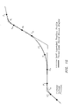
- FIG. 15 is a diagrammatic view illustrating the generation of a speed profile by the motion planner shown in FIG. 2 in accordance with an exemplary embodiment of the present invention.
- FIG. 1 illustrates a motion planner 100 employed within the guidance system 102 of an unmanned ground vehicle 104 in accordance with an exemplary embodiment of the present invention.
- the unmanned ground vehicle 104 comprises any vehicle which is capable of navigating a path to a destination with some level of autonomy, independent of human control.
- the guidance system 102 is coupled to a propulsion system 106 including an engine or motor, drive train, wheels or tracks, and the like, necessary for propelling the vehicle 104 , a vehicle control system 108 including steering and braking systems 110 for steering the ground vehicle 104 , braking or slowing the vehicle 104 , and the like.
- the guidance system 102 may further be coupled to a sensor assembly 112 for sensing obstacles surrounding the vehicle, a global positioning system (GPS) 114 for determining the position of the vehicle 104 as it traverses the path, and a communication system 116 for providing communication between the vehicle 104 and a remotely located operator, computer system, or the like.
- GPS global positioning system
- FIG. 2 further illustrates the motion planner 100 shown in FIG. 1 .
- local path planning is used to revise the reference path determined during the pre-mission path planning. This is primarily because local path planning is simple to implement and works well in simple obstacle settings, such as where the ground vehicle must maneuver around a small obstacle as shown in FIG. 3 .
- local path planners may be incapable of negotiating complex obstacle settings such as a blocked urban canyon, a destroyed bridge, or the like. In such instances, the local path planner may be unable to revise the reference path to generate an obstacle-free path. Consequently, an unmanned ground vehicle employing only local path planning in combination with pre-mission path planning may become trapped because the vehicle's guidance system cannot find a way past the obstacle to the vehicle's destination.
- the motion planner 100 of the present invention comprises a global path planner 118 providing global path planning to revise a reference path due to the obstacle blockage, and a local motion planner 120 providing local motion planning for a look-ahead distance anchored on the revised path determined via global path planning by the global path planner 118 .
- the global path planner 118 carries terrain information and registers obstacle geo-locations in a common global coordinate system, for example via position information obtained using the global positioning system (GPS) 114 , sensor assembly 112 , communication system 116 , or the like, of the unmanned ground vehicle 104 shown in FIG. 1 .
- GPS global positioning system
- sensor assembly 112 sensor assembly 112
- communication system 116 communication system
- the motion planner 100 of the present invention may utilize any conventional global path planning algorithm.
- the motion planner 100 may utilize the Focused D* algorithm developed by the Robotics Institute at Carnegie Mellon University.
- the Focused D* path planning algorithm uses Artificial Intelligence (AI) to enable rapid replanning capability, which makes the Focused D* algorithm suitable for revising the reference path for a ground vehicle 104 in high vehicle speed applications.
- AI Artificial Intelligence
- the Focused D* path planning algorithm is described in Stentz, A., “The Focussed D* Algorithm for Real-Time Replanning,” Proceedings of the International Joint Conference on Artificial Intelligence, August, 1995, which is herein incorporated by reference in its entirety.
- the motion planner 100 further includes a local motion planner 120 to take into account kinematic and dynamic constraints of the ground vehicle 104 .
- the global path planner 118 does not take into account kinematic and dynamic constraints of the ground vehicle 104 when determining a path. Consequently, the path generated by the global path planner 118 may, without correction, include discontinuities 122 . Discontinuities 122 comprise sharp turns along the path calculated by the global path planner 118 , wherein the ground vehicle 104 must abruptly change direction or course. Thus, if the ground vehicle 104 were to follow this path, without further correction or smoothing, the path could typically only be traversed at very low speeds.
- the path 124 developed by the global path planner 118 is hereinafter referred to as a polygonal path 124 .
- the local motion planner 120 refines or smoothes the polygonal path 124 so that the path may be traversed safely (i.e., without accident, severe tipping, roll over, etc.) by the unmanned ground vehicle 104 at a high speed (e.g., at a speed greater than the speed at which the ground vehicle 104 could safely traverse the polygonal path 124 ).
- the local motion planner 120 anchors on the polygonal path 124 generated by the global path planner 118 , while generating a motion profile that contains guidance commands for the unmanned ground vehicle 104 that account for the position, velocity, and heading of the ground vehicle 104 .
- the motion planner 100 will not be trapped by complex obstacle settings since the global path planner 118 provides a general obstacle-free path to the goal location, allowing the motion planner 100 to find paths out of complex obstacle settings.
- the local motion planner 120 of the present invention takes into account kinematic and dynamic constraints of the ground vehicle 104 . With this layered approach, the motion planner 100 provides guidance commands that enable the vehicle control system 108 to perform high speed traversal while avoiding obstacles detected en route.
- FIG. 6 illustrates the method 200 employed by the motion planner 100 for navigating the unmanned ground vehicle 104 to the destination.
- a determination is made, at step 202 , whether an obstacle or obstacles block the reference path being followed. If no obstacle is detected (e.g., via the sensor assembly 112 of the unmanned ground vehicle 104 , or the like), the local motion planner 120 provides local motion planning based on the reference path, at step 204 , taking into account vehicle capability limits for allowing the ground vehicle 104 to operate at a higher speed.
- the global path planner 118 provides global path planning to revise the reference path due to the obstacle blockage, at step 206 , to determine a revised path (i.e., a polygonal path 124 ) to a goal location.
- the goal location that is on the reference path and free of obstacles is selected, at step 208 , to be the ending point of the revised path.
- the local motion planner 120 then provides local motion planning based on the revised (polygonal) path, at step 204 , calculating a motion profile that is within vehicle capability limits.
- This motion profile smoothes discontinuities 122 in the path for allowing the ground vehicle 104 to operate at a higher speed.
- Calculating a motion profile that takes into account the kinematic and dynamic constraints of the ground vehicle 104 requires significant computation. Therefore, for real-time applications, the local motion planner 120 may only generate the motion profile for a look-ahead distance that is a function of vehicle speed and reaction time (e.g., 4 seconds). In this manner, the local motion planner 120 anchors on the polygonal path 124 generated by the global path planner 118 , while generating a motion profile that contains guidance commands for the unmanned ground vehicle 104 that account for the position, velocity, and heading of the ground vehicle 104 .
- the global path planner 118 employing a global path planning algorithm, such as the Focused D* algorithm, or the like, creates a polygonal path 124 from the starting location 126 of the ground vehicle 104 to the goal location 128 .
- a polygonal path is defined as a collection of straight lines created from exiting the center of one cell to entering the center of another cell within a cellular decomposition of the environment 130 being traversed by the unmanned ground vehicle 104 . Due to discontinuities 122 in the direction of the polygonal path 124 , the path 124 cannot be traversed by the unmanned ground vehicle 104 at high speeds. However, the polygonal path 124 does provide a generally obstacle-free path to the goal location 128 and can be computed relatively quickly since vehicle's kinematic and dynamic constraints are not considered.
- the motion planner 100 of the present invention couples the global path planner 118 , employing a global path planning algorithm such as the Focused D* algorithm, or the like with the local motion planner 120 to generate guidance commands that comply with the ground vehicle's kinematic and dynamic constraints.
- the local motion planner 120 adapts the Fillet algorithm proposed by researchers at the Air Force Research Laboratory to take into account ground vehicle's kinematic constraints while constructing a smooth path that can avoid vehicle rollover during high speed traversal.
- the Fillet algorithm is described in Chandler, P., Rasmussen, S., and Pachter, M., “UAV Cooperative Path Planning,” Proceedings of AIAA Guidance, Navigation, and Control Conference , August, 2000, which is herein incorporated by reference in its entirety.
- the Fillet algorithm creates a smooth path based on three anchor points, A, B and C, by searching for tangential arcs of radius r that comply with the vehicle's kinematic constraints. These three anchor points, A, B and C, may be determined based on the polygonal path 124 generated by the global path planner 118 . As a result, the local motion planner 120 is tied to the global path planner 118 and will not be trapped by complex obstacle settings.
- Exemplary high-level logic for the real-time motion planning algorithm 300 implemented by the motion planner 100 of the present invention is shown in FIG. 7 .
- the motion planner 100 needs to revise the reference path, it sets the motion planning mode as either “Full_Replanning,” at step 302 , thereby causing the global path planner 118 to re-compute the polygonal path and the local motion planner 120 to calculate a revised motion profile based on the re-computed polygonal path for at least one look-ahead distance, or “Append_Smooth_Path,” at step 304 , so that the local motion planner 120 appends a segment of motion profile to a saved motion profile until the total accumulated distance for the motion profile is greater than the desired look-ahead distance.
- the motion planning mode is set to “Full_Replanning,” at step 302 , so that the motion profile is re-computed for at least one look-ahead distance.
- the motion planner 100 will then determine whether there are new detected obstacles and the last anchor point (i.e., point C) used for constructing the look-ahead motion profile is no longer a trusted cell (i.e., point C is no longer on the polygonal path determined by the global path planner 118 ), at step 308 .
- the motion profile is completely replanned for at least one look-ahead distance.
- the motion planning mode is therefore set to be “Full_Replanning,” at step 302 .
- the motion planner 100 will further determine whether there are obstacles on the smoothed path within the planned look-ahead distance, at step 310 , for example, by using data received from sensor assembly 112 ( FIG. 1 ).
- the motion planning mode of the local motion planner 120 is set to “Full_Replanning,” at step 302 , so that the motion profile is re-computed for at least one look-ahead distance.
- a determination is made whether the accumulated distance for the remaining motion profile is less than the required look-ahead distance for the current speed of the unmanned ground vehicle 104 , at step 312 .
- the motion planning mode is set to “Append_Smooth_Path,” at step 304 , so that the local motion planner 120 appends a segment of motion profile to the saved motion profile until the total accumulated distance for the motion profile is greater than the desired look-ahead distance. Steps 308 through 312 are repeated at the obstacle occupancy update rate of the ground vehicle 104 .
- FIG. 8 illustrates an exemplary method 400 used by the motion planner 100 for determining a motion profile in accordance with an exemplary embodiment of the present invention.
- a determination is made, at step 402 and step 404 , whether it is necessary to completely re-compute the motion profile or append an additional segment to the motion profile.
- the motion planning mode selected in accordance with the method 300 illustrated in FIG. 7 is used for this determination. If the motion profile is to be completely re-computed (i.e., the motion planning mode is set to “Full_Replanning” at step 302 of method 300 ), the global path planner 118 re-computes the polygonal path 124 .
- a segment is to be appended to the motion profile (i.e., the motion planning mode is set to “Append_Smooth_Path” at step 304 of method 300 )
- three anchor points i.e., anchor points A, B, and C in FIG. 9
- a Fillet algorithm is then used to find a smooth path referenced to the three anchor points complying with the ground vehicle's kinematic constraints of maneuverability, at step 412 , to avoid vehicle rollover during high speed traversal.
- the three anchor points and the curve determined by the Fillet algorithm are used to construct the nominal path.
- the speed of ⁇ miles/hour is used to check obstacle occupancy and to screen the obstacle-free path for the speed profile determination at next step.
- a speed profile is then determined, at step 416 , to take into account vehicle's dynamic constraints such as limits of acceleration/deceleration.
- the obstacle occupancy on the look-ahead motion profile is checked, at step 414 , with the determined speed profile.
- the local motion planner repeats steps 402 through 418 until the motion profile for at least the required look-ahead distance is computed, at step 422 , or until it is determined that the goal location has been reached, at step 420 .
- the motion planner 100 is capable of constructing a motion profile providing high-level guidance commands such as position, velocity, heading, and the like, that are within the capability of the vehicle control system 108 (i.e., the guidance commands can be followed by the vehicle control system 108 ) of the unmanned ground vehicle 104 and leading the unmanned ground vehicle 104 to the destination while avoiding obstacles and minimizing the cost of traversal.
- FIG. 10 illustrates the smoothed path 132 generated by the motion planner 100 of the present invention. With a safe smooth path 132 defined, the ground vehicle 104 can perform high speed traversal through the environment 130 while avoiding obstacles detected en route.
- the global path planner 118 generates a polygonal path 124 as shown in FIG. 11 . It is contemplated that different methods may be used for determining the three anchor points, A, B and C, from this polygonal path 124 . For example, every three consecutive points, where the first point is always the current ground vehicle location, can be set as anchor points, A, B and C. While this method results in a smooth path, the solution is not optimal because the radii used to fit the tangential arcs by the Fillet Algorithm are quite small and, therefore, require the ground vehicle 104 to travel at low speeds.
- FIG. 12 shows a revised path 134 created by selecting anchor points, A, B and C, in this manner. The path 134 is a smoothed version of the polygonal path 124 .
- Anchor points, A, B and C may be found so that the revised path is further smoothed.
- the polygonal path 124 determined by the global path planner 118 is collected from a starting point ⁇ to a location that is a distance ⁇ away from the starting point ⁇ . Distance ⁇ is usually less than the range of onboard perception sensor.
- the starting point ⁇ may be the previous anchor point C, if it is still on the polygonal path 124 and no unknown obstacles have been detected. Otherwise, the current vehicle location will be used as the starting point ⁇ to track the polygonal path 124 .
- each discontinuity 122 in the direction of collected polygonal path 124 is determined and stored in a heading change array which may be stored in memory provided by the guidance system, or the like.
- the last polygonal point collected is added to the heading change array since it cannot be determined whether a discontinuity exists at this point or not.
- the present invention assumes there is always a potential discontinuity in the direction of the path at the last point.
- Anchor point C which is the endpoint, is next determined.
- the initial estimate for anchor point C is the first location in the heading change array that is at least a distance ⁇ away from the first element of the heading change array. Since the last point in the collected polygonal path will always be in the heading change array, the last point will be assigned as anchor point C if the collected solution is a straight line.
- Anchor point B is located at a distance ⁇ away, from anchor point A and the heading of the AB vector is the same as the vehicle heading.
- Distance ⁇ is the distance between anchor point C and point B′, which is the midpoint between the first location in the heading change array and point C. In cases where there is only one heading change, point B′ is simply the midpoint between point A and point C. However, if ⁇ > ⁇ and the heading difference between the AB vector and the AC vector is within a predetermined threshold, distance ⁇ will be limited to be no greater than distance ⁇ so the revised path 134 generated by the Fillet algorithm will not deviate too far away from the polygonal path 124 .
- FIG. 13 illustrates a smoothed path 132 created using the Fillet algorithm with anchor points determined using this method. Because the smoothed path 132 contains fewer changes in heading it is more suitable for high speed traversal than the path 134 illustrated in FIG. 12 which was created by selecting consecutive points.
- the polygonal path 124 from a starting point ⁇ is collected for the determination of three anchor points, A, B, and C.
- a backpointer of the starting point ⁇ may be used to trace the polygonal path 124 since the backpointer is used by the global planning algorithm (e.g., Focused D*) to point to the next cell on the polygonal path 124 . Therefore, by following successive backpointers, the polygonal path 124 may be tracked.
- the starting point ⁇ is not on the polygonal path 124 , this approach may track an invalid path and can even lead the ground vehicle 104 to collide with obstacles.
- the starting point ⁇ should first be verified to be on the polygonal path 124 determined by the global path planner 118 using a global path planning algorithm such as Focused D*.
- a global path planning algorithm such as Focused D*.
- cells traversed by the polygonal path 124 are designated as trusted cells.
- the motion planner 100 need only verify the starting point ⁇ is in one of trusted cells to verify that the starting point ⁇ is on the polygonal path 124 .
- trusted cells are determined and saved in a trusted cell array which may be stored in memory provided by the guidance system 102 .
- This trusted cell array is used to verify whether the starting point ⁇ is in one of these trusted cells. If the starting point ⁇ is not in a trusted cell, the starting point ⁇ is invalid.
- a search is performed to find a trusted cell that is reasonably close to starting point ⁇ . For example, a circular sweep search around starting point ⁇ may be performed.
- a trusted cell is found, a straight line is propagated from starting point ⁇ to this trusted cell. The motion planner 100 checks this straight line path for obstacles because it is possible for obstacles to be located between the starting point ⁇ and this trusted cell.
- the heading difference between the predicted vehicle heading at the starting point ⁇ and the heading of the vector from the starting point ⁇ to the center of this trusted cell is computed. If this heading difference is less than ninety degrees, the center of the cell is assigned as the new starting point to track the polygonal path 124 . In this manner, the motion planner 100 prevents the vehicle from traveling in reverse. If a trusted cell does not result from this process, the motion planner 100 may then search around the starting point ⁇ without the ninety-degree restriction.
- the Fillet algorithm takes into account kinematic constraints of the ground vehicle 104 to avoid vehicle rollover during high speed traversal.
- the Fillet Algorithm joins two polygonal segments formed by the three anchor points A, B, and C with a tangential arc of a radius r.
- the radius of the arc r is constrained by kinematic constraints of the ground vehicle 104 such as turning radius described as a function of vehicle curve speed V c .
- the Fillet algorithm attempts to fit the curve for the highest speed first.
- the Fillet algorithm assigns the curve speed V c as the maximum speed the vehicle is allowed to travel and uses a look-up table to find the corresponding turning rate.
- T ax cos( ⁇ xBA )* BT a +B x
- T ay sin( ⁇ xBA )* BT a +B y
- T bx cos( ⁇ xBC )* BT b +B x
- T by sin( ⁇ xBC )* BT b +B y (6)
- the tangent points, T a and T b are located between line segments AB and BC respectively.
- the distance from T b to C should also be less than half of the magnitude of BC to give sufficient room to prepare for the next possible curve. If T a and T b cannot be determined with the initial value of the curve speed V c , the curve speed V c is reduced by a predetermined amount ⁇ V and the local motion planner 120 again attempts to determine tangent points T a and T b . This process will be repeated until a minimum speed value V c is reached or tangent points T a and T b are determined. If tangent points T a and T b still cannot be determined when V c is reduced to the minimum value, the set of anchor points A, B, and C are rejected by the Fillet algorithm and new anchor points A, B, and C are determined.
- tangent points T a and T b can be determined for a specific turning radius r
- the path segment from anchor point A to tangent point T b , not to anchor point C is stored to determine a speed profile that complies with vehicle's dynamic constraints (e.g., limits of acceleration/deceleration, and the like).
- a speed profile determination algorithm in accordance with the present invention suitable for use by the local motion planner 120 illustrated in FIG. 2 for determining a speed profile is described.
- the speed V c for the last curve i.e., the curve that is newly determined by the Fillet algorithm described in the discussion of FIG. 14
- the speed profile in the stored look-ahead motion profile is then adjusted to enable the last curve speed V c to be maintained.
- a determination is next made whether the last curve speed V c can be achieved at tangent point T a by using the following options, which are ordered in priority of most desirable option to the least desirable option.
- the local motion planner 120 attempts to generate a speed profile wherein the ground vehicle 104 would accelerate from tangent point T′ b to the midpoint m and decelerate to tangent point T a , wherein point m is the midpoint between tangent points T′ b and T a .
- This speed profile when the ground vehicle 104 enters the curve, constant speed is maintained.
- Equation (9) Equation (9)
- the ground vehicle 104 can accelerate from tangent point T′ b until speed V m or point m is reached. After point m, the vehicle will decelerate until tangent point T a or speed V c is reached.
- Option II
- the local motion planner 120 attempts to generate a speed profile wherein the ground vehicle 104 uses a nominal deceleration to decelerate speed V′ c starting from tangent point T′ b .
- the ground vehicle 104 decelerates until tangent point T a or speed V c is reached.
- the local motion planner 120 attempts to generate a speed profile by backtracking from tangent point T′ b to point n, which is one second before tangent point T′ b in the stored look-ahead position profile (point n can be on a curve). If the speed at point n, V n , is less than or equal to speed V c no acceleration is applied from point n to tangent point T a . If the speed V n is greater than speed V c , the local motion planner uses the following equations to compute the required deceleration.
- S, V n , V c are known, V n >V c , and a and t are unknown.
- This option is repeated until one of: the magnitude of the required deceleration is less than or equal to the magnitude of the nominal deceleration and the overall speed profile can be achieved (i.e., speeds at curves are less than or equal to their respective curve speeds determined by the Fillet algorithm.) or the ground vehicle 104 backtracks to the current vehicle position.
- the overall speed profile i.e., speeds at curves are less than or equal to their respective curve speeds determined by the Fillet algorithm.
- the local motion planner 120 attempts to generate a speed profile by backtracking from tangent point T′ b to point n, which is a predetermined distance before tangent point T′ b .
- Maximum deceleration e.g., the maximum deceleration possible by braking the ground vehicle 104
- This option is repeated until the speed V c can be achieved at tangent point T a or at a location before tangent point T a .
- the local motion planner 120 backtracks to the current vehicle position.
- trapezoidal integration is used to propagate position with the determined speed profile.
- the heading is held constant.
- curves heading rate is computed as:
- ⁇ ⁇ ( t ) ⁇ ⁇ ( t - 1 ) + ⁇ ⁇ ( t - 1 ) + ⁇ . ⁇ ( t ) 2 ⁇ dt ( 17 )
- x ⁇ ( t ) x ⁇ ( t - 1 ) + x . ⁇ ( t - 1 ) + x . ⁇ ( t ) 2 ⁇ dt ( 18 )
- y ⁇ ( t ) y ⁇ ( t - 1 ) + y . ⁇ ( t - 1 ) + y .
- the motion planner 100 of the present invention may be implemented as programs of instructions such as software or firmware resident in the memory of the guidance system 102 of the unmanned ground vehicle 104 shown in FIG. 1 . It is understood that the specific order or hierarchies of steps in the methods disclosed are examples of exemplary approaches. Based upon design preferences, it is understood that the specific order or hierarchy of steps in the method can be rearranged while remaining within the scope of the present invention.
- the attached method claims present elements of the various steps in a sample order, and are not meant to be limited to the specific order or hierarchy presented.
Landscapes
- Engineering & Computer Science (AREA)
- Radar, Positioning & Navigation (AREA)
- Remote Sensing (AREA)
- Aviation & Aerospace Engineering (AREA)
- Physics & Mathematics (AREA)
- General Physics & Mathematics (AREA)
- Automation & Control Theory (AREA)
- Control Of Position, Course, Altitude, Or Attitude Of Moving Bodies (AREA)
Abstract
Description
r=V c/Turning_Rate (1)
where Vc is the maximum curve speed. Based on the radius r, tangent lines BTa and BTb may be determined. The magnitude of the tangent lines BTa and BTb are determined as
BT a =r/tan(∠ABC/2) (2)
The (x, y) coordinates of Ta and Tb are:
T ax=cos(∠xBA)*BT a +B x (3)
T ay=sin(∠xBA)*BT a +B y (4)
T bx=cos(∠xBC)*BT b +B x (5)
T by=sin(∠xBC)*BT b +B y (6)
V c =V m +at (7)
where a is the nominal deceleration and t is the delta time to reach tangent point Ta from point m. Equation (7) can be rewritten as
The distance from tangent point T′b to tangent point Ta, denoted as TD, is
Substituting Equation (8) into Equation (9), Equation (9) provides:
Expanding Equation (10) further, provides
TDa=V c 2 −V m 2 (11)
V m=√{square root over (V c 2 −TDa)} (12)
Speed at point m should not exceed speed Vm as computed in Equation (12) in order to provide sufficient time to decelerate the ground vehicle to reach speed Vc at tangent point Ta. The
Option II
where S, Vn, Vc are known, Vn>Vc, and a and t are unknown. This option is repeated until one of: the magnitude of the required deceleration is less than or equal to the magnitude of the nominal deceleration and the overall speed profile can be achieved (i.e., speeds at curves are less than or equal to their respective curve speeds determined by the Fillet algorithm.) or the
Option IV
Position and heading propagation are determined as:
where
{dot over (x)}=V sin ψ
{dot over (j)}=V cos ψ
After the speed profile is determined, both position and speed profiles are saved into the look-ahead motion profile that provides guidance commands to the
Claims (15)
Priority Applications (1)
| Application Number | Priority Date | Filing Date | Title |
|---|---|---|---|
| US11/394,403 US7734387B1 (en) | 2006-03-31 | 2006-03-31 | Motion planner for unmanned ground vehicles traversing at high speeds in partially known environments |
Applications Claiming Priority (1)
| Application Number | Priority Date | Filing Date | Title |
|---|---|---|---|
| US11/394,403 US7734387B1 (en) | 2006-03-31 | 2006-03-31 | Motion planner for unmanned ground vehicles traversing at high speeds in partially known environments |
Publications (1)
| Publication Number | Publication Date |
|---|---|
| US7734387B1 true US7734387B1 (en) | 2010-06-08 |
Family
ID=42226981
Family Applications (1)
| Application Number | Title | Priority Date | Filing Date |
|---|---|---|---|
| US11/394,403 Expired - Fee Related US7734387B1 (en) | 2006-03-31 | 2006-03-31 | Motion planner for unmanned ground vehicles traversing at high speeds in partially known environments |
Country Status (1)
| Country | Link |
|---|---|
| US (1) | US7734387B1 (en) |
Cited By (70)
| Publication number | Priority date | Publication date | Assignee | Title |
|---|---|---|---|---|
| US20090319112A1 (en) * | 2007-09-28 | 2009-12-24 | Honeywell International Inc. | Automatic planning and regulation of the speed of autonomous vehicles |
| US20100299013A1 (en) * | 2009-05-22 | 2010-11-25 | Toyota Motor Engin. & Manufact. | Using topological structure for path planning in semi-structured environments |
| US8589013B2 (en) | 2011-10-25 | 2013-11-19 | Jaybridge Robotics, Inc. | Method and system for dynamically positioning a vehicle relative to another vehicle in motion |
| US8781669B1 (en) | 2012-05-14 | 2014-07-15 | Google Inc. | Consideration of risks in active sensing for an autonomous vehicle |
| WO2014148975A1 (en) * | 2013-03-19 | 2014-09-25 | Scania Cv Ab | Method and system for control of autonomous vehicles |
| US8849494B1 (en) | 2013-03-15 | 2014-09-30 | Google Inc. | Data selection by an autonomous vehicle for trajectory modification |
| CN104334427A (en) * | 2012-05-24 | 2015-02-04 | 罗伯特·博世有限公司 | Method and device for avoiding or mitigating a collision of a vehicle with an obstacle |
| US8996224B1 (en) | 2013-03-15 | 2015-03-31 | Google Inc. | Detecting that an autonomous vehicle is in a stuck condition |
| US9008890B1 (en) | 2013-03-15 | 2015-04-14 | Google Inc. | Augmented trajectories for autonomous vehicles |
| US20150232097A1 (en) * | 2006-03-20 | 2015-08-20 | General Electric Company | Energy management system and method for vehicle systems |
| US20150254988A1 (en) * | 2014-04-17 | 2015-09-10 | SZ DJI Technology Co., Ltd | Flight control for flight-restricted regions |
| US9176500B1 (en) | 2012-05-14 | 2015-11-03 | Google Inc. | Consideration of risks in active sensing for an autonomous vehicle |
| US9188986B2 (en) | 2013-10-01 | 2015-11-17 | Jaybridge Robotics, Inc. | Computer-implemented method and system for dynamically positioning a vehicle relative to another vehicle in motion for on-the-fly offloading operations |
| JP2016081403A (en) * | 2014-10-21 | 2016-05-16 | 株式会社Ihiエアロスペース | Unmanned mobile and its route generation method |
| DE102016111691A1 (en) | 2015-06-29 | 2016-12-29 | Mitsubishi Electric Corporation | Semi-autonomous vehicle and method of controlling a semi-autonomous vehicle |
| US9567078B2 (en) | 2014-07-30 | 2017-02-14 | SZ DJI Technology Co., Ltd | Systems and methods for target tracking |
| US9568915B1 (en) | 2016-02-11 | 2017-02-14 | Mitsubishi Electric Research Laboratories, Inc. | System and method for controlling autonomous or semi-autonomous vehicle |
| US9669851B2 (en) | 2012-11-21 | 2017-06-06 | General Electric Company | Route examination system and method |
| WO2017104775A1 (en) * | 2015-12-14 | 2017-06-22 | Mitsubishi Electric Corporation | Method for controlling vehicle and control system of vehicle |
| US9733625B2 (en) | 2006-03-20 | 2017-08-15 | General Electric Company | Trip optimization system and method for a train |
| US9760092B2 (en) | 2012-03-16 | 2017-09-12 | Waymo Llc | Actively modifying a field of view of an autonomous vehicle in view of constraints |
| US9828010B2 (en) | 2006-03-20 | 2017-11-28 | General Electric Company | System, method and computer software code for determining a mission plan for a powered system using signal aspect information |
| US9834237B2 (en) | 2012-11-21 | 2017-12-05 | General Electric Company | Route examining system and method |
| CN107688342A (en) * | 2017-03-27 | 2018-02-13 | 平安科技(深圳)有限公司 | The obstruction-avoiding control system and method for robot |
| US9933781B1 (en) | 2016-11-23 | 2018-04-03 | Denso International America, Inc. | Data-driven planning for automated driving |
| US9950722B2 (en) | 2003-01-06 | 2018-04-24 | General Electric Company | System and method for vehicle control |
| US10074279B1 (en) | 2017-03-07 | 2018-09-11 | Denso International America, Inc. | Inference-aware motion planning |
| WO2018176593A1 (en) * | 2017-03-31 | 2018-10-04 | 深圳市靖洲科技有限公司 | Local obstacle avoidance path planning method for unmanned bicycle |
| CN108693878A (en) * | 2017-04-06 | 2018-10-23 | 丰田自动车株式会社 | Advance route setting device and advance route setting method |
| US10126136B2 (en) | 2016-06-14 | 2018-11-13 | nuTonomy Inc. | Route planning for an autonomous vehicle |
| CN108898866A (en) * | 2018-07-04 | 2018-11-27 | 深圳万智联合科技有限公司 | A kind of effective intelligent vehicle control system |
| CN109284695A (en) * | 2018-09-03 | 2019-01-29 | 李乐进 | A kind of image makings method for improving based on data mining |
| US10309792B2 (en) | 2016-06-14 | 2019-06-04 | nuTonomy Inc. | Route planning for an autonomous vehicle |
| US10308265B2 (en) | 2006-03-20 | 2019-06-04 | Ge Global Sourcing Llc | Vehicle control system and method |
| US10317899B2 (en) * | 2017-06-16 | 2019-06-11 | nuTonomy Inc. | Intervention in operation of a vehicle having autonomous driving capabilities |
| US10331129B2 (en) | 2016-10-20 | 2019-06-25 | nuTonomy Inc. | Identifying a stopping place for an autonomous vehicle |
| WO2019134142A1 (en) * | 2018-01-05 | 2019-07-11 | 深圳市大疆创新科技有限公司 | Unmanned aerial vehicle control method, unmanned aerial vehicle system, and control device |
| CN110428111A (en) * | 2019-08-08 | 2019-11-08 | 西安工业大学 | Trajectory Planning Method for UAV/UGV Cooperative Long-duration Multi-task Operation |
| US10473470B2 (en) | 2016-10-20 | 2019-11-12 | nuTonomy Inc. | Identifying a stopping place for an autonomous vehicle |
| US10514692B2 (en) | 2017-06-16 | 2019-12-24 | nuTonomy Inc. | Intervention in operation of a vehicle having autonomous driving capabilities |
| KR20200019191A (en) * | 2017-06-16 | 2020-02-21 | 누토노미 인크. | Intervention in the operation of a vehicle with autonomous driving capabilities |
| US10569792B2 (en) | 2006-03-20 | 2020-02-25 | General Electric Company | Vehicle control system and method |
| US10599141B2 (en) | 2017-06-16 | 2020-03-24 | nuTonomy Inc. | Intervention in operation of a vehicle having autonomous driving capabilities |
| US20200117199A1 (en) * | 2018-10-15 | 2020-04-16 | Zoox, Inc. | Trajectory initialization |
| CN111026133A (en) * | 2019-12-31 | 2020-04-17 | 北京易控智驾科技有限公司 | Path planning method and vehicle, computer readable medium |
| US10627810B2 (en) | 2017-06-16 | 2020-04-21 | nuTonomy Inc. | Intervention in operation of a vehicle having autonomous driving capabilities |
| US10681513B2 (en) | 2016-10-20 | 2020-06-09 | nuTonomy Inc. | Identifying a stopping place for an autonomous vehicle |
| US10740988B2 (en) | 2017-06-16 | 2020-08-11 | nuTonomy Inc. | Intervention in operation of a vehicle having autonomous driving capabilities |
| CN111649751A (en) * | 2019-03-04 | 2020-09-11 | 百度(美国)有限责任公司 | Ultra-free sewing method for reference line smoothing |
| US10829116B2 (en) | 2016-07-01 | 2020-11-10 | nuTonomy Inc. | Affecting functions of a vehicle based on function-related information about its environment |
| CN111964683A (en) * | 2020-08-21 | 2020-11-20 | 苏州极目机器人科技有限公司 | Spraying path planning method and device |
| US10857994B2 (en) | 2016-10-20 | 2020-12-08 | Motional Ad Llc | Identifying a stopping place for an autonomous vehicle |
| US10933869B2 (en) | 2017-11-29 | 2021-03-02 | Uatc, Llc | Autonomous vehicle motion control systems and methods |
| WO2021072837A1 (en) * | 2018-10-19 | 2021-04-22 | Geosat Aerospace & Technology Inc. | Unmanned ground vehicle and method for operating unmanned ground vehicle |
| CN112964271A (en) * | 2021-03-15 | 2021-06-15 | 西安交通大学 | Multi-scene-oriented automatic driving planning method and system |
| US11092446B2 (en) | 2016-06-14 | 2021-08-17 | Motional Ad Llc | Route planning for an autonomous vehicle |
| US11112789B2 (en) | 2017-06-16 | 2021-09-07 | Motional Ad Llc | Intervention in operation of a vehicle having autonomous driving capabilities |
| CN114287025A (en) * | 2019-06-14 | 2022-04-05 | 日产自动车株式会社 | Driving assistance method and driving assistance device |
| US11482121B2 (en) | 2015-03-31 | 2022-10-25 | SZ DJI Technology Co., Ltd. | Open platform for vehicle restricted region |
| CN115235488A (en) * | 2021-04-22 | 2022-10-25 | 中煤科工开采研究院有限公司 | Vehicle path planning method, apparatus, system, tool, product and storage medium |
| WO2022222718A1 (en) * | 2021-04-19 | 2022-10-27 | 北京有竹居网络技术有限公司 | Navigation method and apparatus, storage medium, and device |
| US11505190B2 (en) | 2018-05-11 | 2022-11-22 | Volvo Truck Corporation | Method for establishing a path for a vehicle |
| US20230108967A1 (en) * | 2021-09-16 | 2023-04-06 | Nvidia Corporation | Micro-meshes, a structured geometry for computer graphics |
| CN115933628A (en) * | 2022-01-21 | 2023-04-07 | 中国人民解放军海军工程大学 | Human-like bi-level motion planning method with multiple information domains and multiple resolutions |
| CN116414128A (en) * | 2023-03-15 | 2023-07-11 | 北京京东乾石科技有限公司 | Path planning method, path planning model training method and device |
| US20230333563A1 (en) * | 2022-04-19 | 2023-10-19 | Clark Equipment Company | Path planning for automatic mowers |
| WO2023216543A1 (en) * | 2022-05-11 | 2023-11-16 | 深圳市正浩创新科技股份有限公司 | Movement control method for self-moving device, control apparatus, and storage medium |
| US12164306B1 (en) * | 2021-11-19 | 2024-12-10 | Zoox, Inc. | Adaptable origin for location offsets |
| WO2025021049A1 (en) * | 2023-07-21 | 2025-01-30 | 北京斯年智驾科技有限公司 | Autonomous fleet scheduling method and apparatus and electronic device |
| US12317777B2 (en) | 2022-07-08 | 2025-06-03 | Deere & Company | Harvester unloading control system |
Citations (4)
| Publication number | Priority date | Publication date | Assignee | Title |
|---|---|---|---|---|
| US5276383A (en) * | 1990-08-30 | 1994-01-04 | Kabushiki Kaisha Kobe Seiko Sho | Route interpolation method for robot |
| US6151539A (en) * | 1997-11-03 | 2000-11-21 | Volkswagen Ag | Autonomous vehicle arrangement and method for controlling an autonomous vehicle |
| US20050216182A1 (en) * | 2004-03-24 | 2005-09-29 | Hussain Talib S | Vehicle routing and path planning |
| US7272474B1 (en) * | 2004-03-31 | 2007-09-18 | Carnegie Mellon University | Method and system for estimating navigability of terrain |
-
2006
- 2006-03-31 US US11/394,403 patent/US7734387B1/en not_active Expired - Fee Related
Patent Citations (4)
| Publication number | Priority date | Publication date | Assignee | Title |
|---|---|---|---|---|
| US5276383A (en) * | 1990-08-30 | 1994-01-04 | Kabushiki Kaisha Kobe Seiko Sho | Route interpolation method for robot |
| US6151539A (en) * | 1997-11-03 | 2000-11-21 | Volkswagen Ag | Autonomous vehicle arrangement and method for controlling an autonomous vehicle |
| US20050216182A1 (en) * | 2004-03-24 | 2005-09-29 | Hussain Talib S | Vehicle routing and path planning |
| US7272474B1 (en) * | 2004-03-31 | 2007-09-18 | Carnegie Mellon University | Method and system for estimating navigability of terrain |
Non-Patent Citations (2)
| Title |
|---|
| The Focussed D* Algorithm for Real-Time Replanning; Anthony Stentz, Robotics Institute, Carnegie Mellon University, Pittsburgh, Pa 15213; In Proceedings of the International Joint Conference on Artificial Intelligence, Aug. 1995. |
| UAV Cooperative Path Planning; P.R. Chandler, S. Rasmussen, Flight Control Division, Air Force Research Laboratory, Wright-Patterson AFB, OH; M. Patcher, Department of Electrical & Computer Engineering, Air Force Institute of Technology, Wright-Patterson AFB, OH; American Institute of Aeronautics and Astronautics; AIAA Guidance, Navigation & Control Conference & Exhibit, Denver, CO, Aug. 2000. |
Cited By (137)
| Publication number | Priority date | Publication date | Assignee | Title |
|---|---|---|---|---|
| US9950722B2 (en) | 2003-01-06 | 2018-04-24 | General Electric Company | System and method for vehicle control |
| US9733625B2 (en) | 2006-03-20 | 2017-08-15 | General Electric Company | Trip optimization system and method for a train |
| US20160368495A1 (en) * | 2006-03-20 | 2016-12-22 | General Electric Company | Energy management system and method for vehicle systems |
| US9828010B2 (en) | 2006-03-20 | 2017-11-28 | General Electric Company | System, method and computer software code for determining a mission plan for a powered system using signal aspect information |
| US10308265B2 (en) | 2006-03-20 | 2019-06-04 | Ge Global Sourcing Llc | Vehicle control system and method |
| US20150232097A1 (en) * | 2006-03-20 | 2015-08-20 | General Electric Company | Energy management system and method for vehicle systems |
| US10569792B2 (en) | 2006-03-20 | 2020-02-25 | General Electric Company | Vehicle control system and method |
| US9815470B2 (en) * | 2006-03-20 | 2017-11-14 | General Electric Company | Energy management system and method for vehicle systems |
| US9376971B2 (en) * | 2006-03-20 | 2016-06-28 | General Electric Company | Energy management system and method for vehicle systems |
| US7979174B2 (en) * | 2007-09-28 | 2011-07-12 | Honeywell International Inc. | Automatic planning and regulation of the speed of autonomous vehicles |
| US20090319112A1 (en) * | 2007-09-28 | 2009-12-24 | Honeywell International Inc. | Automatic planning and regulation of the speed of autonomous vehicles |
| US8392117B2 (en) * | 2009-05-22 | 2013-03-05 | Toyota Motor Engineering & Manufacturing North America, Inc. | Using topological structure for path planning in semi-structured environments |
| US20100299013A1 (en) * | 2009-05-22 | 2010-11-25 | Toyota Motor Engin. & Manufact. | Using topological structure for path planning in semi-structured environments |
| US8874355B2 (en) | 2011-10-25 | 2014-10-28 | Jaybridge Robotics, Inc. | Method and system for dynamically positioning a vehicle relative to another vehicle in motion |
| US8589013B2 (en) | 2011-10-25 | 2013-11-19 | Jaybridge Robotics, Inc. | Method and system for dynamically positioning a vehicle relative to another vehicle in motion |
| US11829152B2 (en) | 2012-03-16 | 2023-11-28 | Waymo Llc | Actively modifying a field of view of an autonomous vehicle in view of constraints |
| US10466712B2 (en) | 2012-03-16 | 2019-11-05 | Waymo Llc | Actively modifying a field of view of an autonomous vehicle in view of constraints |
| US9760092B2 (en) | 2012-03-16 | 2017-09-12 | Waymo Llc | Actively modifying a field of view of an autonomous vehicle in view of constraints |
| US11507102B2 (en) | 2012-03-16 | 2022-11-22 | Waymo Llc | Actively modifying a field of view of an autonomous vehicle in view of constraints |
| US11294390B2 (en) | 2012-03-16 | 2022-04-05 | Waymo Llc | Actively modifying a field of view of an autonomous vehicle in view of constraints |
| US12230140B2 (en) | 2012-03-16 | 2025-02-18 | Waymo Llc | Actively modifying a field of view of an autonomous vehicle in view of constraints |
| US12187268B2 (en) | 2012-05-14 | 2025-01-07 | Waymo Llc | Consideration of risks in active sensing for an autonomous vehicle |
| US9176500B1 (en) | 2012-05-14 | 2015-11-03 | Google Inc. | Consideration of risks in active sensing for an autonomous vehicle |
| US8781669B1 (en) | 2012-05-14 | 2014-07-15 | Google Inc. | Consideration of risks in active sensing for an autonomous vehicle |
| US10427672B2 (en) | 2012-05-14 | 2019-10-01 | Waymo Llc | Consideration of risks in active sensing for an autonomous vehicle |
| US11427189B2 (en) | 2012-05-14 | 2022-08-30 | Waymo Llc | Consideration of risks in active sensing for an autonomous vehicle |
| US9682704B2 (en) | 2012-05-14 | 2017-06-20 | Google Inc. | Consideration of risks in active sensing for an autonomous vehicle |
| CN104334427A (en) * | 2012-05-24 | 2015-02-04 | 罗伯特·博世有限公司 | Method and device for avoiding or mitigating a collision of a vehicle with an obstacle |
| US10369990B2 (en) * | 2012-05-24 | 2019-08-06 | Robert Bosch Gmbh | Method and device for avoiding or mitigating a collision of a vehicle with an obstacle |
| US20150175159A1 (en) * | 2012-05-24 | 2015-06-25 | Thomas Gussner | Method and device for avoiding or mitigating a collision of a vehicle with an obstacle |
| CN104334427B (en) * | 2012-05-24 | 2017-11-17 | 罗伯特·博世有限公司 | Method and device for avoiding or mitigating a collision of a vehicle with an obstacle |
| US9669851B2 (en) | 2012-11-21 | 2017-06-06 | General Electric Company | Route examination system and method |
| US9834237B2 (en) | 2012-11-21 | 2017-12-05 | General Electric Company | Route examining system and method |
| US9541410B1 (en) * | 2013-03-15 | 2017-01-10 | Google Inc. | Augmented trajectories for autonomous vehicles |
| US9008890B1 (en) | 2013-03-15 | 2015-04-14 | Google Inc. | Augmented trajectories for autonomous vehicles |
| US8996224B1 (en) | 2013-03-15 | 2015-03-31 | Google Inc. | Detecting that an autonomous vehicle is in a stuck condition |
| US8849494B1 (en) | 2013-03-15 | 2014-09-30 | Google Inc. | Data selection by an autonomous vehicle for trajectory modification |
| US9933784B1 (en) | 2013-03-15 | 2018-04-03 | Waymo Llc | Augmented trajectories for autonomous vehicles |
| WO2014148975A1 (en) * | 2013-03-19 | 2014-09-25 | Scania Cv Ab | Method and system for control of autonomous vehicles |
| US9188986B2 (en) | 2013-10-01 | 2015-11-17 | Jaybridge Robotics, Inc. | Computer-implemented method and system for dynamically positioning a vehicle relative to another vehicle in motion for on-the-fly offloading operations |
| US10909860B2 (en) | 2014-04-17 | 2021-02-02 | SZ DJI Technology Co., Ltd. | Flight control for flight-restricted regions |
| US9842505B2 (en) | 2014-04-17 | 2017-12-12 | SZ DJI Technology Co., Ltd | Flight control for flight-restricted regions |
| US12190740B2 (en) | 2014-04-17 | 2025-01-07 | SZ DJI Technology Co., Ltd. | Flight control for flight-restricted regions |
| US9704408B2 (en) | 2014-04-17 | 2017-07-11 | SZ DJI Technology Co., Ltd | Flight control for flight-restricted regions |
| US11810465B2 (en) | 2014-04-17 | 2023-11-07 | SZ DJI Technology Co., Ltd. | Flight control for flight-restricted regions |
| US12198561B2 (en) | 2014-04-17 | 2025-01-14 | SZ DJI Technology Co., Ltd. | Flight control for flight-restricted regions |
| US20150254988A1 (en) * | 2014-04-17 | 2015-09-10 | SZ DJI Technology Co., Ltd | Flight control for flight-restricted regions |
| US11482119B2 (en) | 2014-04-17 | 2022-10-25 | SZ DJI Technology Co., Ltd. | Polygon shaped flight-restriction zones |
| US12394323B2 (en) | 2014-04-17 | 2025-08-19 | SZ DJI Technology Co., Ltd. | Polygon shaped flight-restriction zones |
| US11462116B2 (en) | 2014-04-17 | 2022-10-04 | SZ DJI Technology Co., Ltd. | Polygon shaped vehicle restriction zones |
| US9317036B2 (en) * | 2014-04-17 | 2016-04-19 | SZ DJI Technology Co., Ltd | Flight control for flight-restricted regions |
| US11227501B2 (en) | 2014-04-17 | 2022-01-18 | SZ DJI Technology Co., Ltd. | Flight control for flight-restricted regions |
| US10586463B2 (en) | 2014-04-17 | 2020-03-10 | SZ DJI Technology Co., Ltd. | Polygon shaped flight-restriction zones |
| US9483950B2 (en) | 2014-04-17 | 2016-11-01 | SZ DJI Technology Co., Ltd | Flight control for flight-restricted regions |
| US11106201B2 (en) | 2014-07-30 | 2021-08-31 | SZ DJI Technology Co., Ltd. | Systems and methods for target tracking |
| US9846429B2 (en) | 2014-07-30 | 2017-12-19 | SZ DJI Technology Co., Ltd. | Systems and methods for target tracking |
| US12524007B2 (en) | 2014-07-30 | 2026-01-13 | SZ DJI Technology Co., Ltd. | Systems and methods for target tracking |
| US11194323B2 (en) | 2014-07-30 | 2021-12-07 | SZ DJI Technology Co., Ltd. | Systems and methods for target tracking |
| US9567078B2 (en) | 2014-07-30 | 2017-02-14 | SZ DJI Technology Co., Ltd | Systems and methods for target tracking |
| JP2016081403A (en) * | 2014-10-21 | 2016-05-16 | 株式会社Ihiエアロスペース | Unmanned mobile and its route generation method |
| US11488487B2 (en) | 2015-03-31 | 2022-11-01 | SZ DJI Technology Co., Ltd. | Open platform for flight restricted region |
| US11482121B2 (en) | 2015-03-31 | 2022-10-25 | SZ DJI Technology Co., Ltd. | Open platform for vehicle restricted region |
| US12125394B2 (en) | 2015-03-31 | 2024-10-22 | SZ DJI Technology Co., Ltd. | Open platform for flight restricted region |
| DE102016111691A1 (en) | 2015-06-29 | 2016-12-29 | Mitsubishi Electric Corporation | Semi-autonomous vehicle and method of controlling a semi-autonomous vehicle |
| JP2017016645A (en) * | 2015-06-29 | 2017-01-19 | 三菱電機株式会社 | Semi-autonomous vehicle and method for controlling semi-autonomous vehicle |
| US9821801B2 (en) | 2015-06-29 | 2017-11-21 | Mitsubishi Electric Research Laboratories, Inc. | System and method for controlling semi-autonomous vehicles |
| US10012984B2 (en) | 2015-12-14 | 2018-07-03 | Mitsubishi Electric Research Laboratories, Inc. | System and method for controlling autonomous vehicles |
| WO2017104775A1 (en) * | 2015-12-14 | 2017-06-22 | Mitsubishi Electric Corporation | Method for controlling vehicle and control system of vehicle |
| US9568915B1 (en) | 2016-02-11 | 2017-02-14 | Mitsubishi Electric Research Laboratories, Inc. | System and method for controlling autonomous or semi-autonomous vehicle |
| US11092446B2 (en) | 2016-06-14 | 2021-08-17 | Motional Ad Llc | Route planning for an autonomous vehicle |
| US11022450B2 (en) | 2016-06-14 | 2021-06-01 | Motional Ad Llc | Route planning for an autonomous vehicle |
| US10126136B2 (en) | 2016-06-14 | 2018-11-13 | nuTonomy Inc. | Route planning for an autonomous vehicle |
| US10309792B2 (en) | 2016-06-14 | 2019-06-04 | nuTonomy Inc. | Route planning for an autonomous vehicle |
| US11022449B2 (en) | 2016-06-14 | 2021-06-01 | Motional Ad Llc | Route planning for an autonomous vehicle |
| US10829116B2 (en) | 2016-07-01 | 2020-11-10 | nuTonomy Inc. | Affecting functions of a vehicle based on function-related information about its environment |
| US10473470B2 (en) | 2016-10-20 | 2019-11-12 | nuTonomy Inc. | Identifying a stopping place for an autonomous vehicle |
| US10681513B2 (en) | 2016-10-20 | 2020-06-09 | nuTonomy Inc. | Identifying a stopping place for an autonomous vehicle |
| US10331129B2 (en) | 2016-10-20 | 2019-06-25 | nuTonomy Inc. | Identifying a stopping place for an autonomous vehicle |
| US11711681B2 (en) | 2016-10-20 | 2023-07-25 | Motional Ad Llc | Identifying a stopping place for an autonomous vehicle |
| US10857994B2 (en) | 2016-10-20 | 2020-12-08 | Motional Ad Llc | Identifying a stopping place for an autonomous vehicle |
| US9933781B1 (en) | 2016-11-23 | 2018-04-03 | Denso International America, Inc. | Data-driven planning for automated driving |
| US10074279B1 (en) | 2017-03-07 | 2018-09-11 | Denso International America, Inc. | Inference-aware motion planning |
| CN107688342A (en) * | 2017-03-27 | 2018-02-13 | 平安科技(深圳)有限公司 | The obstruction-avoiding control system and method for robot |
| WO2018176668A1 (en) * | 2017-03-27 | 2018-10-04 | 平安科技(深圳)有限公司 | Robot obstacle avoidance control system and method, robot, and storage medium |
| US11059174B2 (en) | 2017-03-27 | 2021-07-13 | Ping An Technology (Shenzhen) Co., Ltd. | System and method of controlling obstacle avoidance of robot, robot and storage medium |
| CN107688342B (en) * | 2017-03-27 | 2019-05-10 | 平安科技(深圳)有限公司 | Robot obstacle avoidance control system and method |
| WO2018176593A1 (en) * | 2017-03-31 | 2018-10-04 | 深圳市靖洲科技有限公司 | Local obstacle avoidance path planning method for unmanned bicycle |
| CN108693878A (en) * | 2017-04-06 | 2018-10-23 | 丰田自动车株式会社 | Advance route setting device and advance route setting method |
| US10514692B2 (en) | 2017-06-16 | 2019-12-24 | nuTonomy Inc. | Intervention in operation of a vehicle having autonomous driving capabilities |
| US10317899B2 (en) * | 2017-06-16 | 2019-06-11 | nuTonomy Inc. | Intervention in operation of a vehicle having autonomous driving capabilities |
| US11112789B2 (en) | 2017-06-16 | 2021-09-07 | Motional Ad Llc | Intervention in operation of a vehicle having autonomous driving capabilities |
| US12067810B2 (en) | 2017-06-16 | 2024-08-20 | Motional Ad Llc | Intervention in operation of a vehicle having autonomous driving capabilities |
| US10599141B2 (en) | 2017-06-16 | 2020-03-24 | nuTonomy Inc. | Intervention in operation of a vehicle having autonomous driving capabilities |
| US11263830B2 (en) | 2017-06-16 | 2022-03-01 | Motional Ad Llc | Intervention in operation of a vehicle having autonomous driving capabilities |
| KR20220158873A (en) * | 2017-06-16 | 2022-12-01 | 모셔널 에이디 엘엘씨 | Intervention in operation of a vehicle having autonomous driving capabilities |
| KR20200128763A (en) * | 2017-06-16 | 2020-11-16 | 모셔널 에이디 엘엘씨 | Intervention in operation of a vehicle having autonomous driving capabilities |
| US12135547B2 (en) | 2017-06-16 | 2024-11-05 | Motional Ad Llc | Intervention in operation of a vehicle having autonomous driving capabilities |
| US10740988B2 (en) | 2017-06-16 | 2020-08-11 | nuTonomy Inc. | Intervention in operation of a vehicle having autonomous driving capabilities |
| KR20200019191A (en) * | 2017-06-16 | 2020-02-21 | 누토노미 인크. | Intervention in the operation of a vehicle with autonomous driving capabilities |
| US10627810B2 (en) | 2017-06-16 | 2020-04-21 | nuTonomy Inc. | Intervention in operation of a vehicle having autonomous driving capabilities |
| US10933869B2 (en) | 2017-11-29 | 2021-03-02 | Uatc, Llc | Autonomous vehicle motion control systems and methods |
| US12043253B2 (en) | 2017-11-29 | 2024-07-23 | Uatc, Llc | Autonomous vehicle motion control systems and methods |
| US11667283B2 (en) | 2017-11-29 | 2023-06-06 | Uatc, Llc | Autonomous vehicle motion control systems and methods |
| WO2019134142A1 (en) * | 2018-01-05 | 2019-07-11 | 深圳市大疆创新科技有限公司 | Unmanned aerial vehicle control method, unmanned aerial vehicle system, and control device |
| CN110612497A (en) * | 2018-01-05 | 2019-12-24 | 深圳市大疆创新科技有限公司 | UAV control method, UAV system and control device |
| US11505190B2 (en) | 2018-05-11 | 2022-11-22 | Volvo Truck Corporation | Method for establishing a path for a vehicle |
| US11511746B2 (en) * | 2018-05-11 | 2022-11-29 | Volvo Truck Corporation | Method for establishing a path for a vehicle |
| CN108898866A (en) * | 2018-07-04 | 2018-11-27 | 深圳万智联合科技有限公司 | A kind of effective intelligent vehicle control system |
| CN108898866B (en) * | 2018-07-04 | 2021-03-16 | 矩阵数据科技(上海)有限公司 | Intelligent vehicle control system |
| CN109284695A (en) * | 2018-09-03 | 2019-01-29 | 李乐进 | A kind of image makings method for improving based on data mining |
| US20200117199A1 (en) * | 2018-10-15 | 2020-04-16 | Zoox, Inc. | Trajectory initialization |
| US11392127B2 (en) * | 2018-10-15 | 2022-07-19 | Zoox, Inc. | Trajectory initialization |
| US12179737B2 (en) | 2018-10-19 | 2024-12-31 | GEOSAT Aerospace & Technology | Unmanned ground vehicle and method for operating unmanned ground vehicle |
| WO2021072837A1 (en) * | 2018-10-19 | 2021-04-22 | Geosat Aerospace & Technology Inc. | Unmanned ground vehicle and method for operating unmanned ground vehicle |
| US11801825B2 (en) | 2018-10-19 | 2023-10-31 | GEOSAT Aerospace & Technology | Unmanned ground vehicle and method for operating unmanned ground vehicle |
| CN111649751B (en) * | 2019-03-04 | 2023-11-24 | 百度(美国)有限责任公司 | An ultra-free stitching method for reference line smoothing |
| US11066069B2 (en) * | 2019-03-04 | 2021-07-20 | Baidu Usa Llc | Extra-freedom stitch method for reference line smoothing |
| CN111649751A (en) * | 2019-03-04 | 2020-09-11 | 百度(美国)有限责任公司 | Ultra-free sewing method for reference line smoothing |
| CN114287025A (en) * | 2019-06-14 | 2022-04-05 | 日产自动车株式会社 | Driving assistance method and driving assistance device |
| CN110428111A (en) * | 2019-08-08 | 2019-11-08 | 西安工业大学 | Trajectory Planning Method for UAV/UGV Cooperative Long-duration Multi-task Operation |
| CN110428111B (en) * | 2019-08-08 | 2022-12-30 | 西安工业大学 | UAV/UGV (unmanned aerial vehicle/user generated Union vector) cooperative long-time multitask operation trajectory planning method |
| CN111026133B (en) * | 2019-12-31 | 2024-05-28 | 北京易控智驾科技有限公司 | Path planning method, vehicle, and computer readable medium |
| CN111026133A (en) * | 2019-12-31 | 2020-04-17 | 北京易控智驾科技有限公司 | Path planning method and vehicle, computer readable medium |
| CN111964683A (en) * | 2020-08-21 | 2020-11-20 | 苏州极目机器人科技有限公司 | Spraying path planning method and device |
| CN112964271B (en) * | 2021-03-15 | 2023-03-31 | 西安交通大学 | Multi-scene-oriented automatic driving planning method and system |
| CN112964271A (en) * | 2021-03-15 | 2021-06-15 | 西安交通大学 | Multi-scene-oriented automatic driving planning method and system |
| US20240175702A1 (en) * | 2021-04-19 | 2024-05-30 | Beijing Youzhuju Network Technology Co., Ltd. | Navigation method and apparatus, storage medium, and device |
| WO2022222718A1 (en) * | 2021-04-19 | 2022-10-27 | 北京有竹居网络技术有限公司 | Navigation method and apparatus, storage medium, and device |
| CN115235488A (en) * | 2021-04-22 | 2022-10-25 | 中煤科工开采研究院有限公司 | Vehicle path planning method, apparatus, system, tool, product and storage medium |
| US20230108967A1 (en) * | 2021-09-16 | 2023-04-06 | Nvidia Corporation | Micro-meshes, a structured geometry for computer graphics |
| US12164306B1 (en) * | 2021-11-19 | 2024-12-10 | Zoox, Inc. | Adaptable origin for location offsets |
| CN115933628A (en) * | 2022-01-21 | 2023-04-07 | 中国人民解放军海军工程大学 | Human-like bi-level motion planning method with multiple information domains and multiple resolutions |
| US20230333563A1 (en) * | 2022-04-19 | 2023-10-19 | Clark Equipment Company | Path planning for automatic mowers |
| WO2023216543A1 (en) * | 2022-05-11 | 2023-11-16 | 深圳市正浩创新科技股份有限公司 | Movement control method for self-moving device, control apparatus, and storage medium |
| US12317777B2 (en) | 2022-07-08 | 2025-06-03 | Deere & Company | Harvester unloading control system |
| CN116414128A (en) * | 2023-03-15 | 2023-07-11 | 北京京东乾石科技有限公司 | Path planning method, path planning model training method and device |
| WO2025021049A1 (en) * | 2023-07-21 | 2025-01-30 | 北京斯年智驾科技有限公司 | Autonomous fleet scheduling method and apparatus and electronic device |
Similar Documents
| Publication | Publication Date | Title |
|---|---|---|
| US7734387B1 (en) | Motion planner for unmanned ground vehicles traversing at high speeds in partially known environments | |
| EP1913235B1 (en) | Guidance, navigation, and control system for a vehicle | |
| CN102227612B (en) | Controls and systems for autonomous vehicles | |
| US20010023380A1 (en) | Automatic travel control apparatus for vehicle | |
| CN111174797B (en) | Closed area global path planning method | |
| Klaudt et al. | A-priori map information and path planning for automated valet-parking | |
| Bae et al. | Lane change maneuver based on Bezier curve providing comfort experience for autonomous vehicle users | |
| CN114661040B (en) | System, method and controller for graph-based path planning of a host vehicle | |
| CN111857121B (en) | Walking obstacle avoidance method and system for patrol robot based on inertial navigation and laser radar | |
| CN115564140B (en) | Global and local path layered planning method and device for unstructured roads in mining areas | |
| CN117360551A (en) | Underground unmanned vehicle control method, device, electronic equipment and storage medium | |
| JP7716103B2 (en) | Method and apparatus for generating trajectory shape for autonomous vehicles | |
| CN116360420B (en) | A CLF-CBF optimized motion planning and control method for unmanned vehicles | |
| Bom et al. | Nonlinear control for urban vehicles platooning, relying upon a unique kinematic GPS | |
| JP3022354B2 (en) | Method for causing a mobile vehicle to execute a motion combining a combination of arbitrary parallel movement and arbitrary rotation | |
| JP7275646B2 (en) | VEHICLE TRIP CONTROL METHOD AND TRIP CONTROL DEVICE | |
| Hentschel et al. | A hybrid feedback controller for car-like robots–combining reactive obstacle avoidance and global replanning | |
| CN120506967A (en) | Intelligent driving vehicle, obstacle detouring path planning method, device and medium | |
| Moore et al. | Hierarchical task decomposition approach to path planning and control for an omni-directional autonomous mobile robot | |
| Al Badr et al. | Navigating Narrow Margins: A Behavior-Based Control Approach for Autonomous Mining Vehicles in Confined Underground Environments | |
| Cofield et al. | Reactive trajectory planning and tracking for pedestrian-aware autonomous driving in urban environments | |
| Wille et al. | Realizing complex autonomous driving maneuvers the approach taken by team CarOLO at the DARPA urban challenge | |
| US20230127002A1 (en) | Effective path planning systems and methods for autonomous vehicles | |
| Van et al. | Development of An Efficient and Practical Control System in Autonomous Vehicle Competition | |
| Nagel et al. | The Culebra algorithm for path planning and obstacle avoidance in Kat-5 |
Legal Events
| Date | Code | Title | Description |
|---|---|---|---|
| AS | Assignment |
Owner name: ROCKWELL COLLINS, INC.,IOWA Free format text: ASSIGNMENT OF ASSIGNORS INTEREST;ASSIGNORS:YOUNG, SHIH-YIH;JEROME, KRISTEN M.;REEL/FRAME:017757/0365 Effective date: 20060331 |
|
| STCF | Information on status: patent grant |
Free format text: PATENTED CASE |
|
| FPAY | Fee payment |
Year of fee payment: 4 |
|
| MAFP | Maintenance fee payment |
Free format text: PAYMENT OF MAINTENANCE FEE, 8TH YEAR, LARGE ENTITY (ORIGINAL EVENT CODE: M1552) Year of fee payment: 8 |
|
| FEPP | Fee payment procedure |
Free format text: MAINTENANCE FEE REMINDER MAILED (ORIGINAL EVENT CODE: REM.); ENTITY STATUS OF PATENT OWNER: LARGE ENTITY |
|
| LAPS | Lapse for failure to pay maintenance fees |
Free format text: PATENT EXPIRED FOR FAILURE TO PAY MAINTENANCE FEES (ORIGINAL EVENT CODE: EXP.); ENTITY STATUS OF PATENT OWNER: LARGE ENTITY |
|
| STCH | Information on status: patent discontinuation |
Free format text: PATENT EXPIRED DUE TO NONPAYMENT OF MAINTENANCE FEES UNDER 37 CFR 1.362 |
|
| FP | Lapsed due to failure to pay maintenance fee |
Effective date: 20220608 |