US7731139B2 - Suction device and supporting device having the same - Google Patents
Suction device and supporting device having the same Download PDFInfo
- Publication number
- US7731139B2 US7731139B2 US11/802,016 US80201607A US7731139B2 US 7731139 B2 US7731139 B2 US 7731139B2 US 80201607 A US80201607 A US 80201607A US 7731139 B2 US7731139 B2 US 7731139B2
- Authority
- US
- United States
- Prior art keywords
- sleeve
- pivot
- operating
- end portion
- sucking
- Prior art date
- Legal status (The legal status is an assumption and is not a legal conclusion. Google has not performed a legal analysis and makes no representation as to the accuracy of the status listed.)
- Expired - Fee Related, expires
Links
Images


Classifications
-
- F—MECHANICAL ENGINEERING; LIGHTING; HEATING; WEAPONS; BLASTING
- F16—ENGINEERING ELEMENTS AND UNITS; GENERAL MEASURES FOR PRODUCING AND MAINTAINING EFFECTIVE FUNCTIONING OF MACHINES OR INSTALLATIONS; THERMAL INSULATION IN GENERAL
- F16B—DEVICES FOR FASTENING OR SECURING CONSTRUCTIONAL ELEMENTS OR MACHINE PARTS TOGETHER, e.g. NAILS, BOLTS, CIRCLIPS, CLAMPS, CLIPS OR WEDGES; JOINTS OR JOINTING
- F16B47/00—Suction cups for attaching purposes; Equivalent means using adhesives
-
- B—PERFORMING OPERATIONS; TRANSPORTING
- B60—VEHICLES IN GENERAL
- B60R—VEHICLES, VEHICLE FITTINGS, OR VEHICLE PARTS, NOT OTHERWISE PROVIDED FOR
- B60R11/00—Arrangements for holding or mounting articles, not otherwise provided for
-
- B—PERFORMING OPERATIONS; TRANSPORTING
- B60—VEHICLES IN GENERAL
- B60R—VEHICLES, VEHICLE FITTINGS, OR VEHICLE PARTS, NOT OTHERWISE PROVIDED FOR
- B60R11/00—Arrangements for holding or mounting articles, not otherwise provided for
- B60R11/02—Arrangements for holding or mounting articles, not otherwise provided for for radio sets, television sets, telephones, or the like; Arrangement of controls thereof
-
- B—PERFORMING OPERATIONS; TRANSPORTING
- B60—VEHICLES IN GENERAL
- B60R—VEHICLES, VEHICLE FITTINGS, OR VEHICLE PARTS, NOT OTHERWISE PROVIDED FOR
- B60R11/00—Arrangements for holding or mounting articles, not otherwise provided for
- B60R2011/0042—Arrangements for holding or mounting articles, not otherwise provided for characterised by mounting means
- B60R2011/0049—Arrangements for holding or mounting articles, not otherwise provided for characterised by mounting means for non integrated articles
- B60R2011/005—Connection with the vehicle part
- B60R2011/0056—Connection with the vehicle part using suction cups
Definitions
- the invention relates to a suction device, more particularly to a suction device that can be operated using a single hand, and a supporting device having the same.
- a conventional suction device 1 is shown to include a hollow base 11 having a sleeve 14 that extends upwardly from a top surface 111 of the base 11 , a sucking member 12 disposed under the base 11 , a connecting rod 121 extending upwardly from a top surface of the sucking member 12 through the base 11 , and an operating rod 13 .
- the operating rod 13 has a pivot end portion 133 connected pivotally to the connecting rod 121 , an operating end portion 132 opposite to the pivot end portion 133 , and an intermediate fulcrum portion 131 .
- the pivot end portion 133 of the operating rod 13 is in the form of a cam that abuts against the top surface 111 of the base 11 .
- the suction device 1 can be switched from a non-sucking state, where the base 11 is spaced apart from the sucking member 12 and where the operating end portion 132 is pivoted away from the base 11 , as shown in FIG. 1 , to a sucking state, where a peripheral portion 122 of the sucking member 12 is attached sealingly to a supporting surface 101 as a result of pressing of the base 11 thereon and where a central portion 123 of the sucking member 12 is pulled upwardly, thereby forming a vacant space 120 between the supporting surface 101 and the central portion 123 of the sucking member 12 , as shown in FIG. 2 , by operating the operating rod 13 .
- the operating end portion 132 of the operating rod 13 is pivoted toward the base 11 such that the base 11 moves downwardly toward the sucking member 12 due to pressing of the pivot end portion 133 to abut against the peripheral portion 122 of the sucking member 12 until the intermediate fulcrum portion 131 abuts against the base 11 . Thereafter, the operating end portion 132 is pressed downwardly such that an assembly of the pivot end portion 133 of the operating rod 13 , the connecting rod 121 and the central portion 123 of the sucking member 12 move upwardly, thereby forming the vacant space 120 .
- the object of the present invention is to provide a suction device, and a supporting device having the same that can be operated using a single hand.
- a suction device comprises:
- sucking member having a flexible disc body disposed under the sleeve and having a peripheral portion that is adapted to be attached sealingly to a supporting surface and that abuts against the sleeve, and a central portion connected integrally to the peripheral portion and adapted to be spaced apart from the supporting surface, and a connecting body connected integrally to the central portion of the disc body and extending upwardly into the sleeve;
- connecting member disposed in the sleeve and having a first connecting portion connected to the connecting body of the sucking member so as to allow synchronous movement of the connecting member and the connecting body of the sucking member, and a second connecting portion opposite to the first connecting portion in the longitudinal direction;
- an operating rod unit including at least one operating rod that has a pivot end portion extending into the sleeve through the through hole unit in the sleeve and connected pivotally to the second connecting portion of the connecting member, an operating end portion opposite to the pivot end portion, and an intermediate fulcrum portion interconnecting the pivot end portion and the operating end portion, and connected pivotally to the pivot block unit.
- the operating end portion of the operating rod of the operating rod unit is operable so as to pivot the pivot end portion of the operating rod of the operating rod unit upwardly such that an assembly of the connecting member and the connecting body of the sucking member is pulled upwardly, thereby forming a vacant space between the central portion of the disc body of the sucking member and the supporting surface.
- a supporting device adapted for an electronic device.
- the supporting device comprises:
- a suction device including
- a supporting member having an inserting end portion inserted into the sleeve of the suction device, and a mounting end portion adapted to be mounted with the electronic device thereon.
- the operating end portion of the operating rod of the operating rod unit is operable so as to pivot the pivot end portion of the operating rod of the operating rod unit upwardly such that an assembly of the connecting member and the connecting body of the sucking member is pulled upwardly, thereby forming a vacant space between the central portion of the disc body of the sucking member and the supporting surface.
- FIG. 1 is a schematic partly sectional view of a conventional suction device
- FIG. 2 is a schematic partly sectional view showing the conventional suction device when in a state of use
- FIG. 3 is a perspective view showing the first preferred embodiment of a suction device according to the present invention, together with a supporting member to form a supporting device for an electronic device;
- FIG. 4 is an exploded perspective view showing the first preferred embodiment
- FIG. 5 is a schematic sectional view showing the first preferred embodiment when in a non-sucking state
- FIG. 6 is a schematic sectional view showing the first preferred embodiment when in a sucking state
- FIG. 7 is a perspective view showing the first preferred embodiment when in the sucking state
- FIG. 8 is a schematic sectional view showing the second preferred embodiment of a suction device according to the present invention.
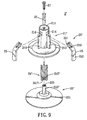
- FIG. 9 is an exploded perspective view showing the third preferred embodiment of a suction device according to the present invention.
- the first preferred embodiment of a suction device 2 is shown to include an upright sleeve 21 , a sucking member 22 , a connecting member 24 , and an operating rod unit 23 .
- the sleeve 21 is made of a hard plastic material, extends along a longitudinal direction (A), and has an open top end 215 , an open bottom end 216 , and a lower end portion 212 having a diameter that increases gradually toward the bottom end 216 (see FIG. 5 ).
- the sleeve 21 further has an annular flange 2121 that extends radially and outwardly from the bottom end 216 .
- the sleeve 21 has an annular outer surface 211 formed with a through hole unit that is disposed adjacent to the top end 215 , and a pivot block unit that is disposed adjacent to the through hole unit.
- the through hole unit includes two diametrically opposed through holes 214 .
- the pivot block unit includes two elongate pivot blocks 213 extending in the longitudinal direction (A) and disposed respectively adjacent to the through holes 214 .
- the sleeve 21 is adapted to permit insertion of an inserting end portion of a supporting member 200 there in to via the top end 215 .
- the supporting member 200 has a mounting end portion 202 for mounting an electronic device 31 thereon, such as a mobile phone, a PDA, or a satellite navigation device, as shown in FIG. 3 .
- the suction device 2 is adapted to cooperate with the support member 200 to constitute a repositionable supporting device for the electronic device 31 .
- the sucking member 22 is made of silicone rubber, and has a flexible disk body 221 and a tubular connecting body 222 .
- the disc body 221 is disposed under the sleeve 21 , and has a peripheral portion 2211 that is adapted to be attached sealingly to a supporting surface 201 and that abuts against the annular flange 2121 of the sleeve 21 , and a central portion 2212 connected integrally to the peripheral portion 2211 and adapted to be spaced apart from the supporting surface 201 .
- the tubular connecting body 222 is connected integrally to the central portion 2212 of the disc body 221 and extends upwardly into the sleeve 21 .
- the connecting member 24 is made of a flexible material, such as plastic or metal, is disposed in the sleeve 21 , and has a first connecting portion connected to the connecting body 222 of the sucking member 22 so as to allow synchronous movement of the connecting member 24 and the connecting body 222 of the sucking member 22 , and a second connecting portion opposite to the first connecting portion in the longitudinal direction (A).
- the connecting member 24 is a U-shaped rod that has parallel vertical rod bodies 242 each having opposite upper and lower ends, and a horizontal rod body 241 interconnecting the lower ends of the vertical rod bodies 242 and extending through two diametrically opposed through holes 224 in the connecting body 222 of the sucking member 22 .
- the horizontal rod body 241 constitutes the first connecting portion of the connecting member 24 .
- the upper ends of the vertical rods 242 constitute the second connecting portion of the connecting member 24 .
- the operating rod unit 23 includes a pair of operating rods 25 , which are made of a flexible material, such as plastic or metal.
- Each operating rod 25 has a pivot end portion 251 extending through a corresponding one of the through holes 214 in the sleeve 21 and into the sleeve 21 and connected pivotally to a corresponding one of the upper ends of the vertical rod bodies 242 of the connecting member 24 , an operating end portion 252 opposite to the pivot end portion 251 , and an intermediate fulcrum portion 253 interconnecting the pivot end portion 251 and the operating end portion 252 , and connected pivotally to a corresponding one of the pivot blocks 213 of the pivot block unit.
- the operating end portions 252 of the operating rods 25 of the operating rod unit 23 are operable so as to pivot the pivot end portions 251 of the operating rods 25 of the operating rod unit 23 upwardly such that an assembly of the connecting member 24 and the connecting body 222 of the sucking member 22 is pulled upwardly, thereby forming a vacant space 20 between the central portion 2212 of the disc body 221 of the sucking member 22 and the supporting surface 201 , as best shown in FIG. 6 .
- the suction device 2 is in a sucking state (see FIG. 7 ).
- FIG. 8 illustrates the second preferred embodiment of a suction device 2 ′ according to this invention, which is a modification of the first preferred embodiment.
- the connecting member 24 ′ is an L-shaped rod that has a lower hook portion 241 ′ and a vertical portion 242 ′.
- the lower hook portion 241 ′ extends through the through holes 224 in the connecting body 222 of the sucking member 22 , and constitutes the first connecting portion of the connecting member 24 ′.
- the vertical portion 242 ′ is connected integrally to the lower hook portion 241 ′, and constitutes the second connecting portion of the connecting member 24 ′.
- the operating rod unit 23 ′ merely has a single operating rod 25 .
- the pivot end portion 251 of the operating rod 25 is connected pivotally to the vertical portion 242 ′ of the connecting member 24 ′.
- FIG. 9 illustrates the third preferred embodiment of a suction device 2 ′′ according to this invention, which is a modification of the first preferred embodiment.
- the through hole unit in the sleeve 21 ′′ includes three spaced-apart through holes 214 disposed adjacent to the top end 215 .
- the pivot block unit of the sleeve 21 ′′ includes three pivot blocks 213 disposed respectively adjacent to the through holes 214 .
- the connecting member 24 ′′ has a base plate 241 ′′ constituting the first connecting portion of the connecting member 24 ′′, and three vertical rods 242 ′′ extending upwardly from a periphery of the base plate 241 ′′ and spaced apart from each other.
- Upper ends of the vertical rods 242 ′′ constitute the second connecting portion of the connecting member 24 ′′.
- a screw fastener 27 extends through the base plate 241 ′′, and is screwed into a threaded hole 225 in the connecting body 222 ′′ of the sucking member 22 ′′, thereby connecting the connecting member 24 ′′ to the connecting body 222 ′′ of the sucking member 22 ′′.
- the operating rod unit 23 ′′ includes three operating rods 25 .
- the pivot end portions 251 of the operating rods 25 extend respectively through the through holes 214 in the sleeve 21 ′′ and into the sleeve 21 ′′, and are connected pivotally and respectively to the upper ends of the vertical rods 242 ′′ of the connecting member 24 ′′.
- the intermediate fulcrum portions 253 of the operating rods 25 are connected pivotally and respectively to the pivot blocks 213 .
- the suction device 2 , 2 ′, 2 ′′ of this invention can be switched to the sucking state by manually operating the operating rod unit 23 , 23 ′, 23 ′′ using a single hand, thereby facilitating operation during use.
Landscapes
- Engineering & Computer Science (AREA)
- Mechanical Engineering (AREA)
- General Engineering & Computer Science (AREA)
- Hooks, Suction Cups, And Attachment By Adhesive Means (AREA)
Abstract
Description
-
- an upright sleeve extending in a longitudinal direction and having a through hole unit and an annular outer surface formed with a pivot block unit that is disposed adjacent to the through hole unit,
- a sucking member having a flexible disc body disposed under the sleeve and having a peripheral portion that is adapted to be attached sealingly to a supporting surface and that abuts against the sleeve, and a central portion connected integrally to the peripheral portion and adapted to be spaced apart from the supporting surface, and a connecting body connected integrally to the central portion of the disc body and extending upwardly into the sleeve,
- a connecting member disposed in the sleeve and having a first connecting portion connected to the connecting body of the sucking member so as to allow synchronous movement of the connecting member and the connecting body of the sucking member, and a second connecting portion opposite to the first connecting portion in the longitudinal direction, and
- an operating rod unit including at least one operating rod that has a pivot end portion extending into the sleeve through the through hole unit in the sleeve and connected pivotally to the second connecting portion of the connecting member, an operating end portion opposite to the pivot end portion, and an intermediate fulcrum portion interconnecting the pivot end portion and the operating end portion, and connected pivotally to the pivot block unit; and
Claims (4)
Applications Claiming Priority (3)
| Application Number | Priority Date | Filing Date | Title |
|---|---|---|---|
| TW95222648U | 2006-12-22 | ||
| TW95222648U TWM318683U (en) | 2006-12-22 | 2006-12-22 | Suction plate and removable electronic device fastener with the same |
| TW095222648 | 2006-12-22 |
Publications (2)
| Publication Number | Publication Date |
|---|---|
| US20080149790A1 US20080149790A1 (en) | 2008-06-26 |
| US7731139B2 true US7731139B2 (en) | 2010-06-08 |
Family
ID=38375445
Family Applications (1)
| Application Number | Title | Priority Date | Filing Date |
|---|---|---|---|
| US11/802,016 Expired - Fee Related US7731139B2 (en) | 2006-12-22 | 2007-05-18 | Suction device and supporting device having the same |
Country Status (3)
| Country | Link |
|---|---|
| US (1) | US7731139B2 (en) |
| DE (1) | DE202007007329U1 (en) |
| TW (1) | TWM318683U (en) |
Cited By (3)
| Publication number | Priority date | Publication date | Assignee | Title |
|---|---|---|---|---|
| US20110139946A1 (en) * | 2009-08-21 | 2011-06-16 | Mike Gonzalez | Universal Flip Stand for portable hand-held devices |
| US20130099075A1 (en) * | 2011-10-21 | 2013-04-25 | Hon Hai Precision Industry Co., Ltd. | Support device |
| CN106592916A (en) * | 2016-11-24 | 2017-04-26 | 国网宁夏电力公司吴忠供电公司 | Anti-electrostatic floor suction-lifting tool |
Families Citing this family (7)
| Publication number | Priority date | Publication date | Assignee | Title |
|---|---|---|---|---|
| US9471108B2 (en) | 2013-09-26 | 2016-10-18 | Lenovo (Beijing) Limited | Electronic device |
| CN104514965B (en) * | 2013-09-26 | 2017-05-24 | 联想(北京)有限公司 | Electronic device |
| CN105221901B (en) * | 2015-09-23 | 2017-06-27 | 怡业股份有限公司 | Mobile device support |
| US10920925B2 (en) * | 2016-04-08 | 2021-02-16 | Tormaxx Gmbh | Suction cup mounting comprising a suction face and a housing |
| USD855349S1 (en) * | 2016-08-31 | 2019-08-06 | Shenzhen Shenghaina Technology Co., Ltd. | Standing support of rotatable displayer |
| CN109506113A (en) * | 2019-01-08 | 2019-03-22 | 朱琳 | A kind of pediatric nursing night surveillance equipment |
| CN112145920A (en) * | 2020-07-05 | 2020-12-29 | 张子辰 | Display fixing seat and support |
Citations (10)
| Publication number | Priority date | Publication date | Assignee | Title |
|---|---|---|---|---|
| US6234435B1 (en) * | 1999-10-13 | 2001-05-22 | Ta Kuang Yeh | Sucking disk support |
| US6308923B1 (en) * | 1999-12-10 | 2001-10-30 | Herman S. Howard | Suction support assembly |
| US6550735B1 (en) * | 2002-01-25 | 2003-04-22 | Zhi-Yuan Zheng | Sucker-type suspension structure |
| US6749160B1 (en) * | 2003-03-12 | 2004-06-15 | Herbert Richter | Suction disc mounting arrangement |
| US7007908B2 (en) * | 2004-06-23 | 2006-03-07 | Wen-Feng Tsay | Sucking disk type hanging pole |
| US7066434B2 (en) * | 2002-08-01 | 2006-06-27 | Golden Peak Plastic Works Limited | Suction-adhesive device |
| US7293750B2 (en) * | 2005-10-05 | 2007-11-13 | Harald Richter | Suction base for an apparatus support device |
| US20070262217A1 (en) * | 2006-05-15 | 2007-11-15 | Leland Wang | Sucking disc apparatus |
| US20070290105A1 (en) * | 2006-06-16 | 2007-12-20 | Comart Corporation | Suction disc unit |
| US20080210833A1 (en) * | 2007-03-02 | 2008-09-04 | Chen-Hsing Wang | Suction device and supporting device having the same |
-
2006
- 2006-12-22 TW TW95222648U patent/TWM318683U/en not_active IP Right Cessation
-
2007
- 2007-05-18 US US11/802,016 patent/US7731139B2/en not_active Expired - Fee Related
- 2007-05-23 DE DE202007007329U patent/DE202007007329U1/en not_active Expired - Lifetime
Patent Citations (10)
| Publication number | Priority date | Publication date | Assignee | Title |
|---|---|---|---|---|
| US6234435B1 (en) * | 1999-10-13 | 2001-05-22 | Ta Kuang Yeh | Sucking disk support |
| US6308923B1 (en) * | 1999-12-10 | 2001-10-30 | Herman S. Howard | Suction support assembly |
| US6550735B1 (en) * | 2002-01-25 | 2003-04-22 | Zhi-Yuan Zheng | Sucker-type suspension structure |
| US7066434B2 (en) * | 2002-08-01 | 2006-06-27 | Golden Peak Plastic Works Limited | Suction-adhesive device |
| US6749160B1 (en) * | 2003-03-12 | 2004-06-15 | Herbert Richter | Suction disc mounting arrangement |
| US7007908B2 (en) * | 2004-06-23 | 2006-03-07 | Wen-Feng Tsay | Sucking disk type hanging pole |
| US7293750B2 (en) * | 2005-10-05 | 2007-11-13 | Harald Richter | Suction base for an apparatus support device |
| US20070262217A1 (en) * | 2006-05-15 | 2007-11-15 | Leland Wang | Sucking disc apparatus |
| US20070290105A1 (en) * | 2006-06-16 | 2007-12-20 | Comart Corporation | Suction disc unit |
| US20080210833A1 (en) * | 2007-03-02 | 2008-09-04 | Chen-Hsing Wang | Suction device and supporting device having the same |
Cited By (3)
| Publication number | Priority date | Publication date | Assignee | Title |
|---|---|---|---|---|
| US20110139946A1 (en) * | 2009-08-21 | 2011-06-16 | Mike Gonzalez | Universal Flip Stand for portable hand-held devices |
| US20130099075A1 (en) * | 2011-10-21 | 2013-04-25 | Hon Hai Precision Industry Co., Ltd. | Support device |
| CN106592916A (en) * | 2016-11-24 | 2017-04-26 | 国网宁夏电力公司吴忠供电公司 | Anti-electrostatic floor suction-lifting tool |
Also Published As
| Publication number | Publication date |
|---|---|
| DE202007007329U1 (en) | 2007-08-16 |
| US20080149790A1 (en) | 2008-06-26 |
| TWM318683U (en) | 2007-09-11 |
Similar Documents
| Publication | Publication Date | Title |
|---|---|---|
| US7731139B2 (en) | Suction device and supporting device having the same | |
| US7658354B2 (en) | Suction device and supporting device having the same | |
| US7661648B2 (en) | Sucker device for a fixing support | |
| US7387284B2 (en) | Mechanism for fastening a pivotal support in any direction | |
| US7793899B2 (en) | Structure for a suction device | |
| USD576693S1 (en) | Push up exercise device | |
| EP2249074B1 (en) | Holder | |
| US7007908B2 (en) | Sucking disk type hanging pole | |
| US7458541B1 (en) | Tissue roll holder | |
| EP1331431A3 (en) | Device for tiltable mounting of a display screen on a wall | |
| US7815155B2 (en) | Suction device and supporting device having the same | |
| US20090127411A1 (en) | Structure and mechanism of windshield mount and pedestal for portable electronics device | |
| US8876072B2 (en) | Holder and sucker thereof | |
| US6550730B1 (en) | Retaining device for replaceable hanger frame | |
| JP5736480B2 (en) | Furniture leg cap | |
| USD551424S1 (en) | Loading ledge device with friction surface | |
| KR200377613Y1 (en) | cellular phone case adhesion holder for automobile | |
| KR100541189B1 (en) | Cellular phone case adhesion holder for automobile | |
| US8184844B2 (en) | Microphone mounter | |
| CN108167608A (en) | Lightweight communication box for easy installation | |
| WO2009117865A1 (en) | Sucker device for a fixing support | |
| JP3123596U (en) | Suction cup structure | |
| GB2457286A (en) | Sucker device for a fixing support | |
| JP5508787B2 (en) | Furniture leg cap | |
| KR200432333Y1 (en) | Easily removable vehicle terminal holder |
Legal Events
| Date | Code | Title | Description |
|---|---|---|---|
| AS | Assignment |
Owner name: LITE-ON TECHNOLOGY CORP., TAIWAN Free format text: ASSIGNMENT OF ASSIGNORS INTEREST;ASSIGNORS:WANG, CHEN-HSING;SU, CHIA-HUNG;REEL/FRAME:019387/0162 Effective date: 20070510 Owner name: LITE-ON TECHNOLOGY CORP.,TAIWAN Free format text: ASSIGNMENT OF ASSIGNORS INTEREST;ASSIGNORS:WANG, CHEN-HSING;SU, CHIA-HUNG;REEL/FRAME:019387/0162 Effective date: 20070510 |
|
| FEPP | Fee payment procedure |
Free format text: PAYOR NUMBER ASSIGNED (ORIGINAL EVENT CODE: ASPN); ENTITY STATUS OF PATENT OWNER: LARGE ENTITY |
|
| AS | Assignment |
Owner name: DUAL MEMRISTOR LTD. CO. LLC, DELAWARE Free format text: ASSIGNMENT OF ASSIGNORS INTEREST;ASSIGNOR:LITE-ON TECHNOLOGY CORPORATION;REEL/FRAME:027775/0583 Effective date: 20111206 |
|
| REMI | Maintenance fee reminder mailed | ||
| LAPS | Lapse for failure to pay maintenance fees | ||
| STCH | Information on status: patent discontinuation |
Free format text: PATENT EXPIRED DUE TO NONPAYMENT OF MAINTENANCE FEES UNDER 37 CFR 1.362 |
|
| STCH | Information on status: patent discontinuation |
Free format text: PATENT EXPIRED DUE TO NONPAYMENT OF MAINTENANCE FEES UNDER 37 CFR 1.362 |
|
| FP | Lapsed due to failure to pay maintenance fee |
Effective date: 20140608 |