US7730756B2 - Turbine vane airfoil reconfiguration method - Google Patents
Turbine vane airfoil reconfiguration method Download PDFInfo
- Publication number
- US7730756B2 US7730756B2 US12/372,168 US37216809A US7730756B2 US 7730756 B2 US7730756 B2 US 7730756B2 US 37216809 A US37216809 A US 37216809A US 7730756 B2 US7730756 B2 US 7730756B2
- Authority
- US
- United States
- Prior art keywords
- turbine vane
- vane segment
- airfoil
- inner shroud
- fixture
- Prior art date
- Legal status (The legal status is an assumption and is not a legal conclusion. Google has not performed a legal analysis and makes no representation as to the accuracy of the status listed.)
- Expired - Fee Related
Links
Images


Classifications
-
- B—PERFORMING OPERATIONS; TRANSPORTING
- B23—MACHINE TOOLS; METAL-WORKING NOT OTHERWISE PROVIDED FOR
- B23P—METAL-WORKING NOT OTHERWISE PROVIDED FOR; COMBINED OPERATIONS; UNIVERSAL MACHINE TOOLS
- B23P6/00—Restoring or reconditioning objects
- B23P6/002—Repairing turbine components, e.g. moving or stationary blades, rotors
-
- F—MECHANICAL ENGINEERING; LIGHTING; HEATING; WEAPONS; BLASTING
- F01—MACHINES OR ENGINES IN GENERAL; ENGINE PLANTS IN GENERAL; STEAM ENGINES
- F01D—NON-POSITIVE DISPLACEMENT MACHINES OR ENGINES, e.g. STEAM TURBINES
- F01D5/00—Blades; Blade-carrying members; Heating, heat-insulating, cooling or antivibration means on the blades or the members
- F01D5/005—Repairing methods or devices
-
- F—MECHANICAL ENGINEERING; LIGHTING; HEATING; WEAPONS; BLASTING
- F05—INDEXING SCHEMES RELATING TO ENGINES OR PUMPS IN VARIOUS SUBCLASSES OF CLASSES F01-F04
- F05D—INDEXING SCHEME FOR ASPECTS RELATING TO NON-POSITIVE-DISPLACEMENT MACHINES OR ENGINES, GAS-TURBINES OR JET-PROPULSION PLANTS
- F05D2230/00—Manufacture
- F05D2230/80—Repairing, retrofitting or upgrading methods
-
- Y—GENERAL TAGGING OF NEW TECHNOLOGICAL DEVELOPMENTS; GENERAL TAGGING OF CROSS-SECTIONAL TECHNOLOGIES SPANNING OVER SEVERAL SECTIONS OF THE IPC; TECHNICAL SUBJECTS COVERED BY FORMER USPC CROSS-REFERENCE ART COLLECTIONS [XRACs] AND DIGESTS
- Y10—TECHNICAL SUBJECTS COVERED BY FORMER USPC
- Y10T—TECHNICAL SUBJECTS COVERED BY FORMER US CLASSIFICATION
- Y10T29/00—Metal working
- Y10T29/37—Impeller making apparatus
-
- Y—GENERAL TAGGING OF NEW TECHNOLOGICAL DEVELOPMENTS; GENERAL TAGGING OF CROSS-SECTIONAL TECHNOLOGIES SPANNING OVER SEVERAL SECTIONS OF THE IPC; TECHNICAL SUBJECTS COVERED BY FORMER USPC CROSS-REFERENCE ART COLLECTIONS [XRACs] AND DIGESTS
- Y10—TECHNICAL SUBJECTS COVERED BY FORMER USPC
- Y10T—TECHNICAL SUBJECTS COVERED BY FORMER US CLASSIFICATION
- Y10T29/00—Metal working
- Y10T29/49—Method of mechanical manufacture
- Y10T29/49316—Impeller making
- Y10T29/49318—Repairing or disassembling
-
- Y—GENERAL TAGGING OF NEW TECHNOLOGICAL DEVELOPMENTS; GENERAL TAGGING OF CROSS-SECTIONAL TECHNOLOGIES SPANNING OVER SEVERAL SECTIONS OF THE IPC; TECHNICAL SUBJECTS COVERED BY FORMER USPC CROSS-REFERENCE ART COLLECTIONS [XRACs] AND DIGESTS
- Y10—TECHNICAL SUBJECTS COVERED BY FORMER USPC
- Y10T—TECHNICAL SUBJECTS COVERED BY FORMER US CLASSIFICATION
- Y10T29/00—Metal working
- Y10T29/49—Method of mechanical manufacture
- Y10T29/49316—Impeller making
- Y10T29/4932—Turbomachine making
- Y10T29/49325—Shaping integrally bladed rotor
-
- Y—GENERAL TAGGING OF NEW TECHNOLOGICAL DEVELOPMENTS; GENERAL TAGGING OF CROSS-SECTIONAL TECHNOLOGIES SPANNING OVER SEVERAL SECTIONS OF THE IPC; TECHNICAL SUBJECTS COVERED BY FORMER USPC CROSS-REFERENCE ART COLLECTIONS [XRACs] AND DIGESTS
- Y10—TECHNICAL SUBJECTS COVERED BY FORMER USPC
- Y10T—TECHNICAL SUBJECTS COVERED BY FORMER US CLASSIFICATION
- Y10T29/00—Metal working
- Y10T29/49—Method of mechanical manufacture
- Y10T29/49316—Impeller making
- Y10T29/49336—Blade making
-
- Y—GENERAL TAGGING OF NEW TECHNOLOGICAL DEVELOPMENTS; GENERAL TAGGING OF CROSS-SECTIONAL TECHNOLOGIES SPANNING OVER SEVERAL SECTIONS OF THE IPC; TECHNICAL SUBJECTS COVERED BY FORMER USPC CROSS-REFERENCE ART COLLECTIONS [XRACs] AND DIGESTS
- Y10—TECHNICAL SUBJECTS COVERED BY FORMER USPC
- Y10T—TECHNICAL SUBJECTS COVERED BY FORMER US CLASSIFICATION
- Y10T29/00—Metal working
- Y10T29/49—Method of mechanical manufacture
- Y10T29/49716—Converting
-
- Y—GENERAL TAGGING OF NEW TECHNOLOGICAL DEVELOPMENTS; GENERAL TAGGING OF CROSS-SECTIONAL TECHNOLOGIES SPANNING OVER SEVERAL SECTIONS OF THE IPC; TECHNICAL SUBJECTS COVERED BY FORMER USPC CROSS-REFERENCE ART COLLECTIONS [XRACs] AND DIGESTS
- Y10—TECHNICAL SUBJECTS COVERED BY FORMER USPC
- Y10T—TECHNICAL SUBJECTS COVERED BY FORMER US CLASSIFICATION
- Y10T29/00—Metal working
- Y10T29/49—Method of mechanical manufacture
- Y10T29/49718—Repairing
-
- Y—GENERAL TAGGING OF NEW TECHNOLOGICAL DEVELOPMENTS; GENERAL TAGGING OF CROSS-SECTIONAL TECHNOLOGIES SPANNING OVER SEVERAL SECTIONS OF THE IPC; TECHNICAL SUBJECTS COVERED BY FORMER USPC CROSS-REFERENCE ART COLLECTIONS [XRACs] AND DIGESTS
- Y10—TECHNICAL SUBJECTS COVERED BY FORMER USPC
- Y10T—TECHNICAL SUBJECTS COVERED BY FORMER US CLASSIFICATION
- Y10T29/00—Metal working
- Y10T29/53—Means to assemble or disassemble
Definitions
- This invention is directed generally to turbine vanes, and more particularly to turbine vane distortion correction systems.
- Airfoils of turbine vane segments often distort during use in a turbine engine in one or more of four ways.
- airfoils may lean, which is downstream deflection.
- Airfoils may twist, which is rotation of the inner shroud about a longitudinal axis extending between the inner and outer shrouds.
- Airfoils may be subjected to racking, which is inner shroud circumferential rotation about an engine centerline relative to the outer housing. Airfoils may also droop, which occurs when down stream portions of the outer housing deflect into the gas path. Such distortion conditions negatively affect performance of the turbine engine and may severely affect the lifecycle of the airfoil and inner and outer shrouds.
- This invention relates to a system for reconfiguring an airfoil of a turbine vane segment.
- the system may be used to straighten an airfoil of a turbine vane segment to remove lean, twist, or racking, or any combination thereof, in a single operation.
- the airfoil may be straightened by applying a force to an inner shroud of the turbine vane segment in a direction that is generally tangential to an outer shroud of the turbine vane segment.
- the system may be formed from a fixture having reaction arms extending from the fixture.
- the reaction arms may be adapted to be inserted into recesses within an outer surface of an outer shroud of the turbine vane segment, wherein the reaction arms are supported by the fixture.
- the system may also include a force exertion system adapted to exert a force on an inner shroud of the turbine vane segment in a direction that is generally tangential to the outer shroud of the turbine vane segment.
- the force exertion system may include a jack, or other appropriate device, for exerting a force onto the inner housing.
- the force exertion system may also include a floating bracket having an extension arm for contacting a first side of the inner shroud of the turbine vane segment and a force application surface adapted to contact a second side of the inner shroud of the turbine vane segment, wherein the second side is adjacent to the first side of the inner shroud.
- the force exertion system may also include a reaction bracket for supporting the jack.
- the system may also include a twist limiting device extending from the fixture for limiting twist of the turbine vane segment.
- the twist limiting device may be, but is not limited to being, a roller extending from the fixture to contact the inner shroud of the airfoil segment to limit twist of the airfoil.
- the system may also include a clamping device adapted to attach the turbine vane segment to the fixture to prevent the reaction arms from being dislocated from the recesses in the turbine vane segment.
- the clamping device may be formed from at least one clamp.
- the system may be used to straighten an airfoil of a turbine vane segment.
- a turbine vane segment may be attached to the system by engaging an outer shroud of the turbine vane segment with reaction arms supported by the fixture. The reaction arms may be inserted into recesses within an outer surface of the shroud.
- An inner shroud of the turbine vane segment may be engaged by a force exertion system for exerting a force in a direction that is generally tangential to the outer shroud.
- Orifices may be created in a convex side, also referred to as the suction side, of an airfoil portion of the turbine vane segment proximate to the outer shroud.
- the orifices may extend generally parallel to a filleted edge between the outer shroud and the at least one airfoil.
- the airfoil may be heated to facilitate twisting of the turbine vane segment. Once heated, a force may be applied to the inner shroud in a direction that is generally tangential to the outer shroud until the airfoil has been twisted to a desired position. After twisting, the orifices in the airfoil may be sealed. In at least one embodiment, the orifices may be sealed while the airfoil remains heated. The orifices may be sealed with a weld or other appropriate method. The airfoil may be reheated after welding to remove any distortion effects from welding.
- An advantage of this invention is that the outer housing may be secured and a force may be applied to the inner shroud of the housing without additional bracing to twist the turbine vane airfoil to a desired position.
- This system and method results in a very efficient system capable of removing lean, twist, or racking, or any combination thereof, in a single system.
- Another advantage of this invention is that the system is capable of repairing turbine vane segments effectively such that the repaired turbine vane segments are comparable to newly manufactured, unused turbine vane segments and are capable of replacing the newly manufactured, unused turbine vane segments, which is a feat not easily accomplished using conventional technologies.
- this invention results in significant time and cost savings.
- FIG. 1 is a perspective view of a turbine vane segment with a plurality of airfoils, wherein an outer shroud is attached to a fixture with reaction arms and a force exertion system is in contact with an inner shroud.
- FIG. 2 is a side view of the force exertion system shown in FIG. 1 .
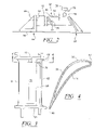
- FIG. 3 is a side view of a single airfoil that forms a portion of a turbine vane segment.
- FIG. 4 is a cross-sectional view of the airfoil shown in FIG. 3 taken at section line 4 - 4 .
- this invention is directed to system 10 for reconfiguring a turbine vane segment 12 .
- the system 10 may be used to straighten an airfoil 14 of a turbine vane segment 12 to remove lean 4 , twist 6 , or racking 8 , or any combination thereof.
- the airfoil 14 may be straightened by applying a force to an inner shroud 16 of the turbine vane segment 12 that is generally tangential to an outer shroud 18 of the turbine vane segment 12 .
- the system 10 may be formed from a fixture 20 configured to support one or more reaction arms 22 .
- the reaction arms 22 may be configured to fit in recesses 24 on an outer surface 26 of an outer shroud 18 of the turbine vane segment 12 to position the turbine vane segment 12 within the system 10 and to prevent the outer shroud 18 from moving.
- the fixture 20 may be any device capable of supporting the turbine vane segment 12 , and specifically, the outer shroud 18 of the segment 12 .
- a clamping device 28 may be used to attach the outer shroud 18 to the fixture 20 and to prevent the reaction arms 22 from becoming dislocated from the outer shroud 18 .
- the clamping device 28 may be a C-clamp or other appropriate device.
- the clamping device 28 may be attached to one or more sides of the outer shroud 18 .
- the clamping device 28 may be attached to opposite sides of the outer shroud 18 , adjacent sides, all four sides, or any combination thereof.
- An axial clamping device 29 may be used to attach the outer shroud 18 to the fixture 20 , as shown in FIG. 1 .
- the axial clamping device 29 may be any appropriate device.
- the system 10 may also include a force exertion system 30 for exerting a force on the inner shroud 16 of the turbine vane segment 12 .
- the force may be exerted on the inner shroud 16 in a direction that is generally parallel, or tangential, to the outer shroud 18 .
- the force exertion system 30 may include a jack 32 for applying a force to the inner shroud 16 .
- the jack 32 may be any conventional jack capable of applying an appropriate force, such as a hydraulic jack.
- the force exertion system 30 may also include a floating bracket 34 that is configured to contact at least two side surfaces 36 , 38 of the inner shroud 16 to apply loads to the inner shroud 16 . In at least one embodiment, as shown in FIG.
- the floating bracket 34 may include an extension arm 40 extending from the floating bracket 34 to contact the first side surface 36 of the inner shroud 16 .
- the floating bracket 34 may also include force application surface 42 for contacting the second side surface 38 of the inner shroud 16 .
- the floating bracket 34 may be configured such that it is capable of applying a force to the inner shroud 16 on the side surface 38 in the tangential direction, but does not constrain the floating bracket 34 in another direction.
- the floating bracket 34 may include extension arm 40 configured to apply a tangential load to the nonparallel second side surface 38 .
- the floating bracket 34 may have other constraints.
- the force exertion system 10 may also include a reaction bracket 44 for supporting the jack 32 and providing the jack 32 with a base from which to apply forces.
- the reaction bracket 44 may be formed from any appropriate configuration for supporting the jack 32 .
- the reaction bracket 44 may include one or more ribs 46 for supporting the attachment of a support plate 48 to a base 50 .
- the jack 32 may be attached to the support plate 48
- the base 50 may be attached to any sufficiently nonmovable foundation enabling a force to be applied to the inner shroud 16 .
- the system 10 may also include a twist limiting device 52 , as shown in FIG. 2 , for limiting twist of the turbine vane segment 12 while a load is applied by the force exertion system 30 .
- the twist limiting device 52 may be attached to and extend from the fixture 20 .
- the twist limiting device 52 may be a roller 54 configured to contact the inner shroud 16 .
- the system 10 may be used to reconfigure an airfoil 14 of the turbine vane segment 12 .
- the turbine vane segment 12 may include a plurality of airfoils 14 , such as three airfoils.
- the system 10 may be used to straighten the airfoils 14 .
- the process begins with the outer shroud 18 being placed into contact with the reaction arms 22 that are attached to the fixture 20 .
- the outer shroud 18 may be secured to the fixture 20 using the clamping devices 28 .
- the inner shroud 16 may be engaged by the force exertion system 30 .
- the force exertion system 30 may be activated to extend the floating bracket 34 to contact the side surfaces 36 , 38 of the inner shroud 16 .
- One or more orifices 56 may be cut into an outer surface 58 of the airfoil 14 to facilitate straightening of the airfoil 14 .
- the orifice 56 may be cut into a convex side 60 , otherwise referred to as the suction side, of the airfoil 14 .
- the orifice 56 may extend from a position in close proximity to a leading edge 62 of the airfoil 14 toward a trailing edge 64 of the airfoil 14 . More specifically, the orifice 56 , in at least one embodiment, may extend from a position in close proximity to a leading edge 62 of the airfoil 14 to between about one inch and about three inches toward the trailing edge 64 .
- the orifice 56 may be about 1.75 inches in length and about 1/16 inches in width.
- the orifice 56 may be positioned inboard of the outer shroud 18 a distance equal to about a width of the filleted weld 66 between the airfoil and the outer shroud 18 .
- the orifice 56 may also be aligned generally parallel with the outer shroud 18 , which positions the orifice 56 generally parallel to a fillet 66 between the outer shroud 18 and the airfoil 14 .
- the orifice 56 may extend from the outer surface 58 to an inner cooling cavity (not shown).
- the airfoil 14 may be heated to facilitate straightening of the airfoil 14 .
- the airfoil 14 may be heated gradually to a temperature of between about 800 degrees Fahrenheit to about 900 degrees Fahrenheit.
- the airfoil 14 may be heated for example, with an oxy-acetylene torch having a rosebud nozzle.
- a load may be applied to the inner shroud 16 of the turbine vane segment 12 .
- the load may be increased until the airfoil has been straightened to a desired position.
- the twist limiting device 52 may be used to prevent overtwisting of the airfoil 14 .
- the twist limiting device 52 may be positioned proximate to the first side surface 36 of the inner shroud 16 at a position that prevents the airfoil 14 from being overtwisted.
- the twist limiting device 52 may also include a guide bar 68 for limiting twist of the airfoil 14 .
- the guide bar 68 may be adjustable enabling different sized inner shrouds to be handled.
- the orifice 56 in the airfoil 14 may be sealed.
- the orifice 56 may be sealed using conventional welding techniques, or other appropriate techniques.
- the orifice 56 may be sealed by welding the orifice 56 closed while the airfoil 14 remains heated and positioned within the fixture 20 and reaction arms 22 while under the load used to twist the airfoil 14 .
- the airfoil 14 may be heated to a temperature of between about 800 degrees Fahrenheit to about 900 degrees Fahrenheit. After sealing the orifice 56 , the airfoil 14 may be heated again to minimize any distortion effects created by the welding.
Landscapes
- Engineering & Computer Science (AREA)
- Mechanical Engineering (AREA)
- General Engineering & Computer Science (AREA)
- Turbine Rotor Nozzle Sealing (AREA)
Abstract
Description
Claims (10)
Priority Applications (1)
| Application Number | Priority Date | Filing Date | Title |
|---|---|---|---|
| US12/372,168 US7730756B2 (en) | 2005-10-13 | 2009-02-17 | Turbine vane airfoil reconfiguration method |
Applications Claiming Priority (2)
| Application Number | Priority Date | Filing Date | Title |
|---|---|---|---|
| US11/249,791 US7503113B2 (en) | 2005-10-13 | 2005-10-13 | Turbine vane airfoil reconfiguration system |
| US12/372,168 US7730756B2 (en) | 2005-10-13 | 2009-02-17 | Turbine vane airfoil reconfiguration method |
Related Parent Applications (1)
| Application Number | Title | Priority Date | Filing Date |
|---|---|---|---|
| US11/249,791 Division US7503113B2 (en) | 2005-10-13 | 2005-10-13 | Turbine vane airfoil reconfiguration system |
Publications (2)
| Publication Number | Publication Date |
|---|---|
| US20090260206A1 US20090260206A1 (en) | 2009-10-22 |
| US7730756B2 true US7730756B2 (en) | 2010-06-08 |
Family
ID=37946825
Family Applications (2)
| Application Number | Title | Priority Date | Filing Date |
|---|---|---|---|
| US11/249,791 Expired - Fee Related US7503113B2 (en) | 2005-10-13 | 2005-10-13 | Turbine vane airfoil reconfiguration system |
| US12/372,168 Expired - Fee Related US7730756B2 (en) | 2005-10-13 | 2009-02-17 | Turbine vane airfoil reconfiguration method |
Family Applications Before (1)
| Application Number | Title | Priority Date | Filing Date |
|---|---|---|---|
| US11/249,791 Expired - Fee Related US7503113B2 (en) | 2005-10-13 | 2005-10-13 | Turbine vane airfoil reconfiguration system |
Country Status (1)
| Country | Link |
|---|---|
| US (2) | US7503113B2 (en) |
Cited By (4)
| Publication number | Priority date | Publication date | Assignee | Title |
|---|---|---|---|---|
| US9138793B2 (en) | 2013-03-14 | 2015-09-22 | Chromalloy Gas Turbine Llc | Process and apparatus to restore distorted features on gas turbine vanes |
| US9566603B2 (en) | 2013-02-27 | 2017-02-14 | United Technologies Corporation | Split coating mask system for gas turbine engine component |
| US9862057B2 (en) | 2012-12-12 | 2018-01-09 | United Technologies Corporation | Vacuum degassing laser-blocking material system and process |
| US10808534B2 (en) | 2017-02-08 | 2020-10-20 | General Electric Company | Reconfigurable maintenance apparatus |
Families Citing this family (12)
| Publication number | Priority date | Publication date | Assignee | Title |
|---|---|---|---|---|
| US7503113B2 (en) * | 2005-10-13 | 2009-03-17 | Siemens Energy, Inc. | Turbine vane airfoil reconfiguration system |
| US7918024B2 (en) * | 2006-01-20 | 2011-04-05 | General Electric Company | Methods and apparatus for manufacturing components |
| US9016551B2 (en) | 2006-11-02 | 2015-04-28 | The Boeing Company | Method and apparatus to construct metal securement member for an aircraft |
| US8186056B2 (en) * | 2007-06-28 | 2012-05-29 | Siemens Energy, Inc. | Turbine vane restoration system |
| US8122601B2 (en) * | 2008-04-15 | 2012-02-28 | United Technologies Corporation | Methods for correcting twist angle in a gas turbine engine blade |
| US8127581B2 (en) * | 2008-04-15 | 2012-03-06 | United Technologies Corporation | Turbine blade twist angle correction tooling |
| US9145792B2 (en) * | 2012-01-31 | 2015-09-29 | General Electric Company | Fixture assembly for repairing a shroud tile of a gas turbine |
| US9206702B2 (en) | 2012-01-31 | 2015-12-08 | General Electric Company | Method for repairing a shroud tile of a gas turbine |
| FR2989130B1 (en) * | 2012-04-05 | 2014-03-28 | Snecma | COMPRESSOR RECTIFIER STAGE FOR A TURBOMACHINE |
| CN105798079B (en) * | 2016-03-14 | 2017-10-24 | 山推工程机械股份有限公司 | A kind of bending apparatus for correcting |
| FR3090030B1 (en) * | 2018-12-12 | 2020-11-20 | Safran Aircraft Engines | Retaining device for removing a turbine engine impeller and method using it |
| JP7291307B1 (en) * | 2023-02-14 | 2023-06-14 | 三菱重工業株式会社 | Fixed blade repair method |
Citations (40)
| Publication number | Priority date | Publication date | Assignee | Title |
|---|---|---|---|---|
| US3032092A (en) | 1957-04-08 | 1962-05-01 | Robert W Erlbacher | Propeller straightening apparatus |
| US3280607A (en) | 1963-08-01 | 1966-10-25 | Sheffield Corp | Machine tool |
| US3621700A (en) * | 1970-03-09 | 1971-11-23 | Richard L Wachtell | Straightening of guide vanes |
| US3818646A (en) * | 1973-01-12 | 1974-06-25 | Trw Inc | Fixture for holding precisely shaped parts |
| US3866448A (en) * | 1973-01-02 | 1975-02-18 | Gen Electric | Apparatus for constructing air cooled turbomachinery blading |
| US4087996A (en) * | 1976-12-13 | 1978-05-09 | General Electric Company | Method and apparatus for correcting distortion in gas turbine engine blades |
| US4498617A (en) | 1983-03-31 | 1985-02-12 | United Technologies Corporation | Method for reshaping a gas turbine engine combustor part |
| US4589175A (en) | 1980-06-02 | 1986-05-20 | United Technologies Corporation | Method for restoring a face on the shroud of a rotor blade |
| US4737417A (en) * | 1984-10-27 | 1988-04-12 | Korber Ag | Cast fixture for holding composite workpieces |
| US4832252A (en) | 1986-12-20 | 1989-05-23 | Refurbished Turbine Components Limited | Parts for and methods of repairing turbine blades |
| US4866828A (en) | 1981-01-12 | 1989-09-19 | Refurbished Turbine Components Limited | Method of repairing turbine blades |
| US4951390A (en) | 1988-09-16 | 1990-08-28 | Refurbished Turbine Components Limited | Turbine blade repair |
| US5048743A (en) | 1990-04-26 | 1991-09-17 | United Technologies Corporation | Rotor blade bonding device |
| US5269057A (en) | 1991-12-24 | 1993-12-14 | Freedom Forge Corporation | Method of making replacement airfoil components |
| US5713233A (en) | 1996-08-30 | 1998-02-03 | Sifco Custom Machining Company | Vane adjustment machine |
| US5913555A (en) | 1996-10-18 | 1999-06-22 | Mtu Motoren- Und Turbinen-Union Muenchen Gmbh | Methods of repairing worn blade tips of compressor and turbine blades |
| US6006407A (en) | 1996-12-05 | 1999-12-28 | General Electric Company | Apparatus for repairing a turbine engine vane segment |
| US6007628A (en) | 1997-12-19 | 1999-12-28 | United Technologies Corporation | Clamping fixture for a rotor blade shroud |
| US6129257A (en) | 1999-12-01 | 2000-10-10 | Allison Engine Company, Inc. | High temperature brazing fixture |
| US6139412A (en) * | 1996-04-30 | 2000-10-31 | United Technologies Corporation | Fixture for manufacturing precisely shaped parts |
| US6172327B1 (en) | 1998-07-14 | 2001-01-09 | General Electric Company | Method for laser twist welding of compressor blisk airfoils |
| US6177038B1 (en) | 1998-11-20 | 2001-01-23 | United Technologies Corporation | Method for orienting an airfoil for processing and for forming a mask for the airfoil |
| US6265022B1 (en) | 1999-08-09 | 2001-07-24 | Abb Alstom Power (Schweiz) Ag | Process of plugging cooling holes of a gas turbine component |
| US20020085917A1 (en) | 2000-12-28 | 2002-07-04 | Roberts Dennis William | System and method for securing a radially inserted integral closure bucket to a turbine rotor wheel assembly having axially inserted buckets |
| US6490791B1 (en) | 2001-06-22 | 2002-12-10 | United Technologies Corporation | Method for repairing cracks in a turbine blade root trailing edge |
| US6531005B1 (en) | 2000-11-17 | 2003-03-11 | General Electric Co. | Heat treatment of weld repaired gas turbine engine components |
| US6532656B1 (en) | 2001-10-10 | 2003-03-18 | General Electric Company | Gas turbine engine compressor blade restoration method |
| US6568993B1 (en) | 2001-12-13 | 2003-05-27 | General Electric Company | Fixture for clamping a gas turbine component and its use in shaping the gas turbine component |
| US6595401B2 (en) | 2000-12-07 | 2003-07-22 | Snecma-Moteurs | Blade maintenance tool, and its application to friction welding of blades |
| US6652369B2 (en) | 2001-12-13 | 2003-11-25 | General Electric Company | Fixture for clamping a gas turbine component and its use in shaping the gas turbine component |
| US6732910B2 (en) | 2001-06-20 | 2004-05-11 | Alstom Technology Ltd | Device and process for producing a soldered joint between two joining partners which can be by means of a common contact surface |
| US20040118175A1 (en) | 2002-12-20 | 2004-06-24 | Lawrence Phillip G. | Fixture for holding metals parts for bending or twist correction |
| US6755924B2 (en) | 2001-12-20 | 2004-06-29 | General Electric Company | Method of restoration of mechanical properties of a cast nickel-based super alloy for serviced aircraft components |
| US6792655B2 (en) | 2001-11-09 | 2004-09-21 | General Electric Company | Apparatus for correcting airfoil twist |
| US20040247442A1 (en) | 2003-06-04 | 2004-12-09 | Ishikawajima-Harima Heavy Industries Co., Ltd. | Turbine blade |
| US6938447B2 (en) | 2002-06-26 | 2005-09-06 | Kabushiki Kaisha Toshiba | Apparatus and method of correcting deformation of gas turbine blade |
| US20070011872A1 (en) | 2005-07-15 | 2007-01-18 | United Technologies Corporation | System and method for repairing a gas turbine engine component |
| US7328496B2 (en) | 2003-10-31 | 2008-02-12 | General Electric Company | Apparatus for rebuilding gas turbine engine blades |
| US7503113B2 (en) * | 2005-10-13 | 2009-03-17 | Siemens Energy, Inc. | Turbine vane airfoil reconfiguration system |
| US7536783B2 (en) * | 2005-10-13 | 2009-05-26 | Siemens Energy, Inc. | Turbine vane airfoil reconfiguration method |
Family Cites Families (1)
| Publication number | Priority date | Publication date | Assignee | Title |
|---|---|---|---|---|
| US3030092A (en) * | 1958-04-10 | 1962-04-17 | Degussa | Device for a gastight fixing of ceramic tubes in high temperature furnaces |
-
2005
- 2005-10-13 US US11/249,791 patent/US7503113B2/en not_active Expired - Fee Related
-
2009
- 2009-02-17 US US12/372,168 patent/US7730756B2/en not_active Expired - Fee Related
Patent Citations (40)
| Publication number | Priority date | Publication date | Assignee | Title |
|---|---|---|---|---|
| US3032092A (en) | 1957-04-08 | 1962-05-01 | Robert W Erlbacher | Propeller straightening apparatus |
| US3280607A (en) | 1963-08-01 | 1966-10-25 | Sheffield Corp | Machine tool |
| US3621700A (en) * | 1970-03-09 | 1971-11-23 | Richard L Wachtell | Straightening of guide vanes |
| US3866448A (en) * | 1973-01-02 | 1975-02-18 | Gen Electric | Apparatus for constructing air cooled turbomachinery blading |
| US3818646A (en) * | 1973-01-12 | 1974-06-25 | Trw Inc | Fixture for holding precisely shaped parts |
| US4087996A (en) * | 1976-12-13 | 1978-05-09 | General Electric Company | Method and apparatus for correcting distortion in gas turbine engine blades |
| US4589175A (en) | 1980-06-02 | 1986-05-20 | United Technologies Corporation | Method for restoring a face on the shroud of a rotor blade |
| US4866828A (en) | 1981-01-12 | 1989-09-19 | Refurbished Turbine Components Limited | Method of repairing turbine blades |
| US4498617A (en) | 1983-03-31 | 1985-02-12 | United Technologies Corporation | Method for reshaping a gas turbine engine combustor part |
| US4737417A (en) * | 1984-10-27 | 1988-04-12 | Korber Ag | Cast fixture for holding composite workpieces |
| US4832252A (en) | 1986-12-20 | 1989-05-23 | Refurbished Turbine Components Limited | Parts for and methods of repairing turbine blades |
| US4951390A (en) | 1988-09-16 | 1990-08-28 | Refurbished Turbine Components Limited | Turbine blade repair |
| US5048743A (en) | 1990-04-26 | 1991-09-17 | United Technologies Corporation | Rotor blade bonding device |
| US5269057A (en) | 1991-12-24 | 1993-12-14 | Freedom Forge Corporation | Method of making replacement airfoil components |
| US6139412A (en) * | 1996-04-30 | 2000-10-31 | United Technologies Corporation | Fixture for manufacturing precisely shaped parts |
| US5713233A (en) | 1996-08-30 | 1998-02-03 | Sifco Custom Machining Company | Vane adjustment machine |
| US5913555A (en) | 1996-10-18 | 1999-06-22 | Mtu Motoren- Und Turbinen-Union Muenchen Gmbh | Methods of repairing worn blade tips of compressor and turbine blades |
| US6006407A (en) | 1996-12-05 | 1999-12-28 | General Electric Company | Apparatus for repairing a turbine engine vane segment |
| US6007628A (en) | 1997-12-19 | 1999-12-28 | United Technologies Corporation | Clamping fixture for a rotor blade shroud |
| US6172327B1 (en) | 1998-07-14 | 2001-01-09 | General Electric Company | Method for laser twist welding of compressor blisk airfoils |
| US6177038B1 (en) | 1998-11-20 | 2001-01-23 | United Technologies Corporation | Method for orienting an airfoil for processing and for forming a mask for the airfoil |
| US6265022B1 (en) | 1999-08-09 | 2001-07-24 | Abb Alstom Power (Schweiz) Ag | Process of plugging cooling holes of a gas turbine component |
| US6129257A (en) | 1999-12-01 | 2000-10-10 | Allison Engine Company, Inc. | High temperature brazing fixture |
| US6531005B1 (en) | 2000-11-17 | 2003-03-11 | General Electric Co. | Heat treatment of weld repaired gas turbine engine components |
| US6595401B2 (en) | 2000-12-07 | 2003-07-22 | Snecma-Moteurs | Blade maintenance tool, and its application to friction welding of blades |
| US20020085917A1 (en) | 2000-12-28 | 2002-07-04 | Roberts Dennis William | System and method for securing a radially inserted integral closure bucket to a turbine rotor wheel assembly having axially inserted buckets |
| US6732910B2 (en) | 2001-06-20 | 2004-05-11 | Alstom Technology Ltd | Device and process for producing a soldered joint between two joining partners which can be by means of a common contact surface |
| US6490791B1 (en) | 2001-06-22 | 2002-12-10 | United Technologies Corporation | Method for repairing cracks in a turbine blade root trailing edge |
| US6532656B1 (en) | 2001-10-10 | 2003-03-18 | General Electric Company | Gas turbine engine compressor blade restoration method |
| US6792655B2 (en) | 2001-11-09 | 2004-09-21 | General Electric Company | Apparatus for correcting airfoil twist |
| US6652369B2 (en) | 2001-12-13 | 2003-11-25 | General Electric Company | Fixture for clamping a gas turbine component and its use in shaping the gas turbine component |
| US6568993B1 (en) | 2001-12-13 | 2003-05-27 | General Electric Company | Fixture for clamping a gas turbine component and its use in shaping the gas turbine component |
| US6755924B2 (en) | 2001-12-20 | 2004-06-29 | General Electric Company | Method of restoration of mechanical properties of a cast nickel-based super alloy for serviced aircraft components |
| US6938447B2 (en) | 2002-06-26 | 2005-09-06 | Kabushiki Kaisha Toshiba | Apparatus and method of correcting deformation of gas turbine blade |
| US20040118175A1 (en) | 2002-12-20 | 2004-06-24 | Lawrence Phillip G. | Fixture for holding metals parts for bending or twist correction |
| US20040247442A1 (en) | 2003-06-04 | 2004-12-09 | Ishikawajima-Harima Heavy Industries Co., Ltd. | Turbine blade |
| US7328496B2 (en) | 2003-10-31 | 2008-02-12 | General Electric Company | Apparatus for rebuilding gas turbine engine blades |
| US20070011872A1 (en) | 2005-07-15 | 2007-01-18 | United Technologies Corporation | System and method for repairing a gas turbine engine component |
| US7503113B2 (en) * | 2005-10-13 | 2009-03-17 | Siemens Energy, Inc. | Turbine vane airfoil reconfiguration system |
| US7536783B2 (en) * | 2005-10-13 | 2009-05-26 | Siemens Energy, Inc. | Turbine vane airfoil reconfiguration method |
Cited By (5)
| Publication number | Priority date | Publication date | Assignee | Title |
|---|---|---|---|---|
| US9862057B2 (en) | 2012-12-12 | 2018-01-09 | United Technologies Corporation | Vacuum degassing laser-blocking material system and process |
| US9566603B2 (en) | 2013-02-27 | 2017-02-14 | United Technologies Corporation | Split coating mask system for gas turbine engine component |
| US9138793B2 (en) | 2013-03-14 | 2015-09-22 | Chromalloy Gas Turbine Llc | Process and apparatus to restore distorted features on gas turbine vanes |
| US10808534B2 (en) | 2017-02-08 | 2020-10-20 | General Electric Company | Reconfigurable maintenance apparatus |
| US11248465B2 (en) | 2017-02-08 | 2022-02-15 | General Electric Company | Reconfigurable maintenance apparatus |
Also Published As
| Publication number | Publication date |
|---|---|
| US20070084048A1 (en) | 2007-04-19 |
| US20090260206A1 (en) | 2009-10-22 |
| US7503113B2 (en) | 2009-03-17 |
Similar Documents
| Publication | Publication Date | Title |
|---|---|---|
| US7730756B2 (en) | Turbine vane airfoil reconfiguration method | |
| JP5264165B2 (en) | Method and apparatus for enhancing airfoil fatigue notch performance | |
| EP0359585B1 (en) | Turbine blade repair | |
| US7334306B2 (en) | Methods and apparatus for fabricating a turbine nozzle assembly | |
| US6219916B1 (en) | Method for linear friction welding and product made by such method | |
| JPH10196309A (en) | Turbine blade platform seal | |
| US8925200B2 (en) | Method for repairing an airfoil | |
| US7536783B2 (en) | Turbine vane airfoil reconfiguration method | |
| KR19980042275A (en) | Rotor blade replacement method and integrated blade type rotor manufacturing method | |
| JP2005106053A (en) | Centrally mounted cutter teeth on shrouded turbine blades | |
| US8186056B2 (en) | Turbine vane restoration system | |
| US20060207309A1 (en) | Bending device and method for bending a plate | |
| US12312973B2 (en) | Airfoil joining apparatus and methods | |
| CA2044654C (en) | Repair of turbine blades | |
| EP1564371A2 (en) | Method of repair for cast article | |
| US20200359793A1 (en) | Method for repairing an upstream rail of a turbine engine turbine casing | |
| EP3132887B1 (en) | Method for repair of a diaphragm of a rotary machine | |
| US20170198584A1 (en) | Systems and methods for repairing a component of a rotary machine | |
| US7784717B2 (en) | Methods and apparatus for fabricating components |
Legal Events
| Date | Code | Title | Description |
|---|---|---|---|
| AS | Assignment |
Owner name: CHROMALLOY GAS TURBINE CORPORATION, NEW YORK Free format text: ASSIGNMENT OF ONE-HALF OF ASSIGNOR'S INTEREST;ASSIGNOR:SIEMENS POWER GENERATION, INC.;REEL/FRAME:022293/0759 Effective date: 20061211 Owner name: CHROMALLOY GAS TURBINE CORPORATION,NEW YORK Free format text: ASSIGNMENT OF ONE-HALF OF ASSIGNOR'S INTEREST;ASSIGNOR:SIEMENS POWER GENERATION, INC.;REEL/FRAME:022293/0759 Effective date: 20061211 Owner name: SIEMENS WESTINGHOUSE POWER CORPORATION, FLORIDA Free format text: ASSIGNMENT OF ASSIGNORS INTEREST;ASSIGNORS:GOSLING, MARTIN C.;DAVIS, JEFFERSON;KANG, YONG;REEL/FRAME:022293/0704;SIGNING DATES FROM 20050609 TO 20051004 Owner name: SIEMENS POWER GENERATION, INC., FLORIDA Free format text: CHANGE OF NAME;ASSIGNOR:SIEMENS WESTINGHOUSE POWER CORPORATION;REEL/FRAME:022293/0773 Effective date: 20050801 Owner name: SIEMENS ENERGY, INC., FLORIDA Free format text: CHANGE OF NAME;ASSIGNOR:SIEMENS POWER GENERATION, INC.;REEL/FRAME:022293/0780 Effective date: 20081001 Owner name: SIEMENS WESTINGHOUSE POWER CORPORATION,FLORIDA Free format text: ASSIGNMENT OF ASSIGNORS INTEREST;ASSIGNORS:GOSLING, MARTIN C.;DAVIS, JEFFERSON;KANG, YONG;SIGNING DATES FROM 20050609 TO 20051004;REEL/FRAME:022293/0704 Owner name: SIEMENS POWER GENERATION, INC.,FLORIDA Free format text: CHANGE OF NAME;ASSIGNOR:SIEMENS WESTINGHOUSE POWER CORPORATION;REEL/FRAME:022293/0773 Effective date: 20050801 Owner name: SIEMENS ENERGY, INC.,FLORIDA Free format text: CHANGE OF NAME;ASSIGNOR:SIEMENS POWER GENERATION, INC.;REEL/FRAME:022293/0780 Effective date: 20081001 |
|
| AS | Assignment |
Owner name: CHROMALLOY GAS TURBINE LLC,NEW YORK Free format text: CHANGE OF NAME;ASSIGNOR:CHROMALLOY GAS TURBINE CORPORATION;REEL/FRAME:024262/0983 Effective date: 20071203 |
|
| FPAY | Fee payment |
Year of fee payment: 4 |
|
| AS | Assignment |
Owner name: BARCLAYS BANK PLC, NEW YORK Free format text: NOTICE AND CONFIRMATION OF GRANT OF SECURITY INTEREST IN PATENTS;ASSIGNORS:BLUE JAY ACQUISITION CORPORATION;SEQUA CORPORATION;CASCO INVESTORS CORPORATION;AND OTHERS;SIGNING DATES FROM 20160326 TO 20160328;REEL/FRAME:038300/0825 |
|
| AS | Assignment |
Owner name: BARCLAYS BANK PLC, NEW YORK Free format text: FIRST LIEN INTELLECTUAL PROPERTY SECURITY AGREEMENT;ASSIGNORS:CHROMALLOY GAS TURBINE LLC;SEQUA CORPORATION;REEL/FRAME:042374/0474 Effective date: 20170428 Owner name: BARCLAYS BANK PLC, NEW YORK Free format text: SECOND LIEN INTELLECTUAL PROPERTY SECURITY AGREEMENT;ASSIGNORS:CHROMALLOY GAS TURBINE LLC;SEQUA CORPORATION;REEL/FRAME:042374/0448 Effective date: 20170428 |
|
| FEPP | Fee payment procedure |
Free format text: MAINTENANCE FEE REMINDER MAILED (ORIGINAL EVENT CODE: REM.) |
|
| LAPS | Lapse for failure to pay maintenance fees |
Free format text: PATENT EXPIRED FOR FAILURE TO PAY MAINTENANCE FEES (ORIGINAL EVENT CODE: EXP.) |
|
| STCH | Information on status: patent discontinuation |
Free format text: PATENT EXPIRED DUE TO NONPAYMENT OF MAINTENANCE FEES UNDER 37 CFR 1.362 |
|
| FP | Lapsed due to failure to pay maintenance fee |
Effective date: 20180608 |
|
| AS | Assignment |
Owner name: BELAC LLC, FLORIDA Free format text: RELEASE OF SECURITY INTEREST IN INTELLECTUAL PROPERTY COLLATERAL (RELEASE OF REEL 042374 FRAME 0448;ASSIGNOR:BARCLAYS BANK PLC;REEL/FRAME:060063/0473 Effective date: 20220513 Owner name: CHROMALLY GAS TURBINE LLC, FLORIDA Free format text: RELEASE OF SECURITY INTEREST IN INTELLECTUAL PROPERTY COLLATERAL (RELEASE OF REEL 042374 FRAME 0448;ASSIGNOR:BARCLAYS BANK PLC;REEL/FRAME:060063/0473 Effective date: 20220513 Owner name: SEQUA CORPORATION, FLORIDA Free format text: RELEASE OF SECURITY INTEREST IN INTELLECTUAL PROPERTY COLLATERAL (RELEASE OF REEL 042374 FRAME 0448;ASSIGNOR:BARCLAYS BANK PLC;REEL/FRAME:060063/0473 Effective date: 20220513 |
|
| AS | Assignment |
Owner name: BELAC LLC, FLORIDA Free format text: RELEASE OF SECURITY INTEREST IN INTELLECTUAL PROPERTY COLLATERAL;ASSIGNOR:BARCLAYS BANK PLC, AS COLLATERAL AGENT;REEL/FRAME:061994/0423 Effective date: 20221123 Owner name: CHROMALLOY GAS TURBINE LLC, FLORIDA Free format text: RELEASE OF SECURITY INTEREST IN INTELLECTUAL PROPERTY COLLATERAL;ASSIGNOR:BARCLAYS BANK PLC, AS COLLATERAL AGENT;REEL/FRAME:061994/0423 Effective date: 20221123 Owner name: SEQUA CORPORATION, FLORIDA Free format text: RELEASE OF SECURITY INTEREST IN INTELLECTUAL PROPERTY COLLATERAL;ASSIGNOR:BARCLAYS BANK PLC, AS COLLATERAL AGENT;REEL/FRAME:061994/0423 Effective date: 20221123 |