US7729599B2 - Optimized determination of the after-run voltage in DC motors - Google Patents
Optimized determination of the after-run voltage in DC motors Download PDFInfo
- Publication number
- US7729599B2 US7729599B2 US11/886,697 US88669706A US7729599B2 US 7729599 B2 US7729599 B2 US 7729599B2 US 88669706 A US88669706 A US 88669706A US 7729599 B2 US7729599 B2 US 7729599B2
- Authority
- US
- United States
- Prior art keywords
- pulse
- motor
- time period
- specified
- run voltage
- Prior art date
- Legal status (The legal status is an assumption and is not a legal conclusion. Google has not performed a legal analysis and makes no representation as to the accuracy of the status listed.)
- Active, expires
Links
- 238000000034 method Methods 0.000 claims abstract description 11
- 238000011156 evaluation Methods 0.000 claims abstract description 4
- 238000005259 measurement Methods 0.000 description 4
- 238000012935 Averaging Methods 0.000 description 2
- 239000003990 capacitor Substances 0.000 description 2
- 238000010586 diagram Methods 0.000 description 2
- 230000000694 effects Effects 0.000 description 2
- 230000003071 parasitic effect Effects 0.000 description 2
- 239000006185 dispersion Substances 0.000 description 1
- 239000012530 fluid Substances 0.000 description 1
- 238000012545 processing Methods 0.000 description 1
- 230000002035 prolonged effect Effects 0.000 description 1
- 239000004065 semiconductor Substances 0.000 description 1
Images
Classifications
-
- H—ELECTRICITY
- H02—GENERATION; CONVERSION OR DISTRIBUTION OF ELECTRIC POWER
- H02P—CONTROL OR REGULATION OF ELECTRIC MOTORS, ELECTRIC GENERATORS OR DYNAMO-ELECTRIC CONVERTERS; CONTROLLING TRANSFORMERS, REACTORS OR CHOKE COILS
- H02P7/00—Arrangements for regulating or controlling the speed or torque of electric DC motors
- H02P7/06—Arrangements for regulating or controlling the speed or torque of electric DC motors for regulating or controlling an individual DC dynamo-electric motor by varying field or armature current
- H02P7/18—Arrangements for regulating or controlling the speed or torque of electric DC motors for regulating or controlling an individual DC dynamo-electric motor by varying field or armature current by master control with auxiliary power
- H02P7/24—Arrangements for regulating or controlling the speed or torque of electric DC motors for regulating or controlling an individual DC dynamo-electric motor by varying field or armature current by master control with auxiliary power using discharge tubes or semiconductor devices
- H02P7/28—Arrangements for regulating or controlling the speed or torque of electric DC motors for regulating or controlling an individual DC dynamo-electric motor by varying field or armature current by master control with auxiliary power using discharge tubes or semiconductor devices using semiconductor devices
- H02P7/285—Arrangements for regulating or controlling the speed or torque of electric DC motors for regulating or controlling an individual DC dynamo-electric motor by varying field or armature current by master control with auxiliary power using discharge tubes or semiconductor devices using semiconductor devices controlling armature supply only
- H02P7/29—Arrangements for regulating or controlling the speed or torque of electric DC motors for regulating or controlling an individual DC dynamo-electric motor by varying field or armature current by master control with auxiliary power using discharge tubes or semiconductor devices using semiconductor devices controlling armature supply only using pulse modulation
-
- B—PERFORMING OPERATIONS; TRANSPORTING
- B60—VEHICLES IN GENERAL
- B60T—VEHICLE BRAKE CONTROL SYSTEMS OR PARTS THEREOF; BRAKE CONTROL SYSTEMS OR PARTS THEREOF, IN GENERAL; ARRANGEMENT OF BRAKING ELEMENTS ON VEHICLES IN GENERAL; PORTABLE DEVICES FOR PREVENTING UNWANTED MOVEMENT OF VEHICLES; VEHICLE MODIFICATIONS TO FACILITATE COOLING OF BRAKES
- B60T8/00—Arrangements for adjusting wheel-braking force to meet varying vehicular or ground-surface conditions, e.g. limiting or varying distribution of braking force
- B60T8/32—Arrangements for adjusting wheel-braking force to meet varying vehicular or ground-surface conditions, e.g. limiting or varying distribution of braking force responsive to a speed condition, e.g. acceleration or deceleration
- B60T8/34—Arrangements for adjusting wheel-braking force to meet varying vehicular or ground-surface conditions, e.g. limiting or varying distribution of braking force responsive to a speed condition, e.g. acceleration or deceleration having a fluid pressure regulator responsive to a speed condition
- B60T8/40—Arrangements for adjusting wheel-braking force to meet varying vehicular or ground-surface conditions, e.g. limiting or varying distribution of braking force responsive to a speed condition, e.g. acceleration or deceleration having a fluid pressure regulator responsive to a speed condition comprising an additional fluid circuit including fluid pressurising means for modifying the pressure of the braking fluid, e.g. including wheel driven pumps for detecting a speed condition, or pumps which are controlled by means independent of the braking system
- B60T8/404—Control of the pump unit
- B60T8/4059—Control of the pump unit involving the rate of delivery
Definitions
- the present invention relates to a device for determining the after-run voltage of a direct current motor, and a corresponding method.
- the rotational speed may be derived from the after-run voltage when the motor is controlled in a cycled manner.
- the after-run voltage of a pump motor in the uncycled no-pulse period is used to determine the rotational speed of the pump.
- a method is described in published German patent document DE 199 46 177 for estimating an intake pressure between a master brake cylinder and an intake valve of a wheel braking cylinder in a motor vehicle brake system.
- the intake pressure is estimated, taking into account an after-run voltage of a motor, operable in a cycled manner, of a pump for conveying brake fluid.
- the after-run voltage is usually determined via averaging instantaneous values of the motor voltage in the no-pulse period. This averaging is necessary because the generator after-run voltage is permeated via rather large interference signals as the result of brush sparking.
- the recording of the instantaneous values is controlled, for example, via clocking by a microprocessor, it being necessary to record multiple instantaneous values to obtain a measuring signal of sufficient quality since the dispersion of the instantaneous values may be very large.
- the rotational speed of the direct current motor is then computed from the average value thus obtained.
- the present invention provides a device and a method for determining the after-run voltage of a direct current motor which is operated via cycled control.
- the direct current motor is controlled via PWM control and a first specifiable pulse/no-pulse ratio.
- An evaluation means is provided for determining an after-run voltage variable which is representative of the after-run voltage of the motor.
- the direct current motor is controlled via a specifiable, variable second pulse/no-pulse ratio.
- the essence of the present invention is that the current applied to the direct current motor via the second pulse/no-pulse ratio is reduced to a lower value during a specifiable first time period t decay , based on the current applied to the motor during the cycled control via the first specifiable pulse/no-pulse ratio.
- the object is achieved of minimizing interference produced as the result of parasitic inductivities and capacitances in the control unit and/or in the supply lines.
- the after-run voltage variable is determined following the control of the direct current motor via the second pulse/no-pulse ratio. Alternatively or optionally, the determination may also be made following the first time period. It is also possible to begin the determination when a specifiable threshold value is reached, the specifiable threshold value in particular being zero or essentially zero.
- the after-run voltage variable is determined during a second time period t measurement .
- the control of the direct current motor generally returns to normal operation, i.e., the motor is controlled via the first pulse/no-pulse ratio. This may be the case, for example, following the second time period.
- the direct current motor is re-controlled via the first pulse/no-pulse ratio after a time period composed of t decay and t measurement .
- the pulse width modulation (PWM) duty factor in the second pulse/no-pulse ratio is advantageously reduced from the controlled value (i.e., the pulse height) of the first pulse/no-pulse ratio to the threshold value. In one optional application of the present invention, this reduction occurs in a linear manner.
- the time period for the pause control of the PWM duty factor in the second pulse/no-pulse ratio is continuously increased, i.e., prolonged, during the first time period. This increase may also occur, for example, in a linear manner.
- FIG. 1 schematically illustrates the circuitry of a direct current motor for high-frequency clocking.
- FIGS. 2 a through 2 e show the variation over time of the voltage and current in the direct current motor and in the vehicle electrical system.
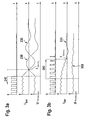
- FIGS. 3 a and 3 b show a comparison between the related art and the application of the present invention after control via the first pulse/no-pulse ratio.
- FIG. 1 schematically shows a circuit configuration used to provide high-frequency control of a (pump) motor, for example in the brake system of a motor vehicle.
- a control device 100 is provided which in turn operates direct current motor 160 in a cycled manner.
- transistor 140 is controlled via a corresponding connection 145 for the cycled control of direct current motor 160 .
- Coil 120 provided in control device 100 is intended to function as a filter, in conjunction with capacitor 130 , to filter out fluctuations from the vehicle electrical system.
- the motor voltage is usually measured in the supply path downstream from semiconductor switch 140 . This is achieved using a voltage divider, which is illustrated as diode 150 in FIG. 1 .
- the voltage divider represents a low-pass filter via which the after-run voltage may be processed for a corresponding evaluation.
- the processing typically occurs via use of an AD converter in a microprocessor, the signal being cyclically read in a cycle specified via the operating system (for example, 1 ms, 5 ms . . . ).
- the vehicle electrical system voltage i.e., battery voltage
- the battery current may be determined via a measuring or clamp terminal 190 .
- a corresponding measuring device for determining the motor current is possible via a device 170 .
- FIGS. 2 a through 2 e illustrate the cycled control of the direct current motor as known from the related art.
- the cycled control before and after the after-run voltage measurement is illustrated in FIG. 2 a .
- the motor in normal operation 240 the motor is usually controlled in a cycled manner via equidistant pulses having a corresponding pulse length.
- FIG. 2 b shows the current that flows through direct current motor 160 .
- motor current I mot drops after the cycled control is interrupted (current decay phase). Since no further control occurs, the motor current drops to a value that is essentially zero. This drop in the motor current occurs in a first time period t decay .
- FIG. 3 a shows the switching off of the cycled control in a magnified illustration.
- the direct current motor is initially controlled via equidistant pulses.
- the vehicle electrical system in the form of the battery current or the vehicle electrical system voltage shows the typical wave pattern corresponding to cycled control.
- fluctuations occur in the battery current or in the vehicle electrical system voltage having current peaks or voltage peaks 230 , respectively.
- the reason for these fluctuations is that the energy stored in the vehicle electrical system inductivity and the filter reactor dies down when the motor is switched off. This results in the internal vehicle electrical system LC oscillating circuit formed from the filter elements in the control device being excited, and in parasitic inductivities and capacitances in the supply line. This generates interference signals in the voltage which can be picked up at terminals 180 , as well as in the current detected at measuring point 190 .
- a controlled, i.e., retarded, decay of the vehicle electrical system current is achieved during the cycled control.
- Such a controlled decay of the vehicle electrical system current is shown, for example, with reference to the linear change in the PWM duty factor illustrated in FIG. 3 b .
- the pulse length used during the cycled control is linearly reduced until the pulse length has been reduced to essentially zero.
- the current decay during phase 200 occurs in a cascaded fashion as a result of the linear reduction of the cycled control. After the cycled control has been completely switched off, only small fluctuations 310 remain, which have only slight effects on the determination of the after-run voltage.
- the interpulse pauses of this second pulse/no-pulse ratio may also be successively increased in region 240 .
- current I mot applied to motor 160 is compared to a specifiable threshold value. The after-run voltage is not determined until current I mot falls below the specified threshold value.
Landscapes
- Engineering & Computer Science (AREA)
- Physics & Mathematics (AREA)
- Fluid Mechanics (AREA)
- Power Engineering (AREA)
- Transportation (AREA)
- Mechanical Engineering (AREA)
- Control Of Direct Current Motors (AREA)
Abstract
Description
Claims (10)
Applications Claiming Priority (4)
| Application Number | Priority Date | Filing Date | Title |
|---|---|---|---|
| DE102005013143A DE102005013143A1 (en) | 2005-03-22 | 2005-03-22 | Optimized detection of the tracking voltage in DC motors |
| DE102005013143 | 2005-03-22 | ||
| DE10-2005-013-143.3 | 2005-05-22 | ||
| PCT/EP2006/050442 WO2006100139A1 (en) | 2005-03-22 | 2006-01-25 | Optimal capturing of a dc-motor residual voltage |
Publications (2)
| Publication Number | Publication Date |
|---|---|
| US20090190904A1 US20090190904A1 (en) | 2009-07-30 |
| US7729599B2 true US7729599B2 (en) | 2010-06-01 |
Family
ID=36143206
Family Applications (1)
| Application Number | Title | Priority Date | Filing Date |
|---|---|---|---|
| US11/886,697 Active 2027-03-17 US7729599B2 (en) | 2005-03-22 | 2006-01-25 | Optimized determination of the after-run voltage in DC motors |
Country Status (6)
| Country | Link |
|---|---|
| US (1) | US7729599B2 (en) |
| EP (1) | EP1863689B1 (en) |
| CN (1) | CN101146703B (en) |
| DE (2) | DE102005013143A1 (en) |
| ES (1) | ES2351842T3 (en) |
| WO (1) | WO2006100139A1 (en) |
Cited By (1)
| Publication number | Priority date | Publication date | Assignee | Title |
|---|---|---|---|---|
| US20140142826A1 (en) * | 2012-11-16 | 2014-05-22 | Nissin Kogyo Co., Ltd. | Vehicle brake hydraulic pressure control apparatus |
Families Citing this family (7)
| Publication number | Priority date | Publication date | Assignee | Title |
|---|---|---|---|---|
| DE102008040925A1 (en) * | 2007-09-24 | 2009-04-09 | Robert Bosch Gmbh | Method for controlling electric motor by pulse width modulation, involves generating control pulses with reference pulse width repetition factor and temporally varying pulse widths and pulse distances as function of recorded parameter |
| DE102008040927B4 (en) | 2007-09-24 | 2022-07-14 | Robert Bosch Gmbh | Method for determining measured values in a clocked controlled system |
| DE102007060949A1 (en) | 2007-12-18 | 2009-06-25 | Robert Bosch Gmbh | Device for determining rotational speed of electric machine, particularly direct current motor, on basis of regenerative residual voltage, has circuit with main switch, which is arranged in current path of electric machine |
| DE102008040929A1 (en) | 2008-08-01 | 2010-02-04 | Robert Bosch Gmbh | Method for measuring value determination in a clocked controlled system |
| DE102008040931B4 (en) * | 2008-08-01 | 2021-04-22 | Robert Bosch Gmbh | Method for determining measured values in a clocked controlled system |
| JP5796483B2 (en) * | 2011-12-27 | 2015-10-21 | 株式会社アドヴィックス | Brake control device for vehicle |
| JP5730829B2 (en) * | 2012-09-05 | 2015-06-10 | 日信工業株式会社 | Motor control device and vehicle brake hydraulic pressure control device |
Citations (8)
| Publication number | Priority date | Publication date | Assignee | Title |
|---|---|---|---|---|
| US5153492A (en) * | 1989-07-31 | 1992-10-06 | Msi Corporation | Servo amplifier |
| DE4303206A1 (en) | 1993-02-04 | 1994-08-11 | Teves Gmbh Alfred | Method and circuit arrangement for determining the pedal force as a controlled variable for a brake system with anti-lock control |
| DE19528697A1 (en) | 1995-08-04 | 1997-02-06 | Bosch Gmbh Robert | Method and device for determining a pressure variable |
| US5811947A (en) | 1993-07-31 | 1998-09-22 | Lucas Industries Plc | Testing and speed control of electric motors in vehicles having electronically controlled braking systems |
| DE19914404A1 (en) | 1999-03-30 | 2000-10-05 | Bosch Gmbh Robert | Method and device for controlling a pump of a brake system |
| DE19946177A1 (en) | 1999-09-21 | 2001-04-19 | Asclepion Meditec Ag | Removal of laser-ablation waste products generated in e.g. corrective photorefractive keratectomy of the cornea, employs charged electrodes to sweep them away rapidly |
| DE10158846A1 (en) | 2001-11-27 | 2003-07-03 | Alcoa Fujikura Gmbh | control unit |
| DE10359224A1 (en) | 2003-10-01 | 2005-04-21 | Bosch Gmbh Robert | Optimized detection of the tracking voltage in DC motors |
Family Cites Families (2)
| Publication number | Priority date | Publication date | Assignee | Title |
|---|---|---|---|---|
| TW308754B (en) * | 1994-12-28 | 1997-06-21 | Yamaha Motor Co Ltd | |
| WO2005007475A1 (en) * | 2003-07-11 | 2005-01-27 | Continental Teves Ag & Co.Ohg | Electronic control method for a slip-controlled motor vehicle brake system |
-
2005
- 2005-03-22 DE DE102005013143A patent/DE102005013143A1/en not_active Withdrawn
-
2006
- 2006-01-25 DE DE502006008228T patent/DE502006008228D1/en not_active Expired - Lifetime
- 2006-01-25 US US11/886,697 patent/US7729599B2/en active Active
- 2006-01-25 EP EP06701162A patent/EP1863689B1/en not_active Expired - Lifetime
- 2006-01-25 WO PCT/EP2006/050442 patent/WO2006100139A1/en not_active Ceased
- 2006-01-25 CN CN2006800092416A patent/CN101146703B/en not_active Expired - Fee Related
- 2006-01-25 ES ES06701162T patent/ES2351842T3/en not_active Expired - Lifetime
Patent Citations (8)
| Publication number | Priority date | Publication date | Assignee | Title |
|---|---|---|---|---|
| US5153492A (en) * | 1989-07-31 | 1992-10-06 | Msi Corporation | Servo amplifier |
| DE4303206A1 (en) | 1993-02-04 | 1994-08-11 | Teves Gmbh Alfred | Method and circuit arrangement for determining the pedal force as a controlled variable for a brake system with anti-lock control |
| US5811947A (en) | 1993-07-31 | 1998-09-22 | Lucas Industries Plc | Testing and speed control of electric motors in vehicles having electronically controlled braking systems |
| DE19528697A1 (en) | 1995-08-04 | 1997-02-06 | Bosch Gmbh Robert | Method and device for determining a pressure variable |
| DE19914404A1 (en) | 1999-03-30 | 2000-10-05 | Bosch Gmbh Robert | Method and device for controlling a pump of a brake system |
| DE19946177A1 (en) | 1999-09-21 | 2001-04-19 | Asclepion Meditec Ag | Removal of laser-ablation waste products generated in e.g. corrective photorefractive keratectomy of the cornea, employs charged electrodes to sweep them away rapidly |
| DE10158846A1 (en) | 2001-11-27 | 2003-07-03 | Alcoa Fujikura Gmbh | control unit |
| DE10359224A1 (en) | 2003-10-01 | 2005-04-21 | Bosch Gmbh Robert | Optimized detection of the tracking voltage in DC motors |
Cited By (2)
| Publication number | Priority date | Publication date | Assignee | Title |
|---|---|---|---|---|
| US20140142826A1 (en) * | 2012-11-16 | 2014-05-22 | Nissin Kogyo Co., Ltd. | Vehicle brake hydraulic pressure control apparatus |
| US9346448B2 (en) * | 2012-11-16 | 2016-05-24 | Nissin Kogyo Co., Ltd | Vehicle brake hydraulic pressure control apparatus with pump motor malfunction detection |
Also Published As
| Publication number | Publication date |
|---|---|
| CN101146703B (en) | 2011-09-07 |
| US20090190904A1 (en) | 2009-07-30 |
| CN101146703A (en) | 2008-03-19 |
| WO2006100139A1 (en) | 2006-09-28 |
| EP1863689B1 (en) | 2010-11-03 |
| DE502006008228D1 (en) | 2010-12-16 |
| EP1863689A1 (en) | 2007-12-12 |
| DE102005013143A1 (en) | 2006-09-28 |
| ES2351842T3 (en) | 2011-02-11 |
Similar Documents
| Publication | Publication Date | Title |
|---|---|---|
| US8018188B2 (en) | Method and device for determining the position of a rotor of a brushless and sensorless electric motor | |
| US8562304B2 (en) | Electrical motor activation method having load torque adaptation | |
| KR101982946B1 (en) | Method for determining a position and/or change in position of a hydraulic pump of a motor vehicle brake system and motor vehicle brake system | |
| US8513909B2 (en) | Processing a motor variable of a DC motor and actuating device for a motor vehicle | |
| US7423403B2 (en) | Motor control system | |
| US9285400B2 (en) | Method for determining current in a polyphase machine | |
| US7729599B2 (en) | Optimized determination of the after-run voltage in DC motors | |
| US8527176B2 (en) | Method for measuring pressure in a pressure regulation unit of a motor vehicle braking system, and a motor vehicle braking system in which the method is implemented | |
| US7027315B2 (en) | Circuit arrangement for operating an electrical machine | |
| US20030067795A1 (en) | Synchronous rectification for low voltage motor drive | |
| US8836269B2 (en) | Method for detecting blockages of electrically commutated electric motors | |
| US20090324205A1 (en) | Pulse count control for brushed dc motor driven by pulse width modulation | |
| JPH11514094A (en) | DC motor armature temperature detector | |
| US8692606B2 (en) | External power transistor control | |
| JP2003536357A (en) | How to supply digital current ripple signal | |
| CN103782503A (en) | Electronically commutated electric motor | |
| US20050093491A1 (en) | Method for controlling a brushless electric motor | |
| US11955920B2 (en) | Method for controlling an electric motor having a mechanical commutator | |
| US11777423B2 (en) | Method for determining a movement of a rotor | |
| KR100978508B1 (en) | Driving device for brush-type DC motor for fuel pump of automobile and its control method | |
| CN108780991A (en) | Method for driving the active bridge rectification device in automobile and its enforcement body | |
| GB2393519A (en) | A method and device for measuring the number of revolutions of a pump motor | |
| HK40075422A (en) | Method for controlling an electric motor having a mechanical commutator |
Legal Events
| Date | Code | Title | Description |
|---|---|---|---|
| AS | Assignment |
Owner name: ROBERT BOSCH GMBH,GERMANY Free format text: ASSIGNMENT OF ASSIGNORS INTEREST;ASSIGNORS:EMDE, CHRISTOPH;PEVELING, WOLFGANG;KOERNER, GOTTHILF;AND OTHERS;SIGNING DATES FROM 20071024 TO 20071120;REEL/FRAME:024143/0472 |
|
| STCF | Information on status: patent grant |
Free format text: PATENTED CASE |
|
| FPAY | Fee payment |
Year of fee payment: 4 |
|
| MAFP | Maintenance fee payment |
Free format text: PAYMENT OF MAINTENANCE FEE, 8TH YEAR, LARGE ENTITY (ORIGINAL EVENT CODE: M1552) Year of fee payment: 8 |
|
| MAFP | Maintenance fee payment |
Free format text: PAYMENT OF MAINTENANCE FEE, 12TH YEAR, LARGE ENTITY (ORIGINAL EVENT CODE: M1553); ENTITY STATUS OF PATENT OWNER: LARGE ENTITY Year of fee payment: 12 |