US7726382B2 - Vehicle body frame, die-cast product, mold for die-cast product and die-cast method - Google Patents
Vehicle body frame, die-cast product, mold for die-cast product and die-cast method Download PDFInfo
- Publication number
- US7726382B2 US7726382B2 US11/605,389 US60538906A US7726382B2 US 7726382 B2 US7726382 B2 US 7726382B2 US 60538906 A US60538906 A US 60538906A US 7726382 B2 US7726382 B2 US 7726382B2
- Authority
- US
- United States
- Prior art keywords
- mold
- core
- die
- splints
- cast product
- Prior art date
- Legal status (The legal status is an assumption and is not a legal conclusion. Google has not performed a legal analysis and makes no representation as to the accuracy of the status listed.)
- Expired - Fee Related, expires
Links
Images


Classifications
-
- B—PERFORMING OPERATIONS; TRANSPORTING
- B22—CASTING; POWDER METALLURGY
- B22C—FOUNDRY MOULDING
- B22C9/00—Moulds or cores; Moulding processes
- B22C9/10—Cores; Manufacture or installation of cores
- B22C9/108—Installation of cores
-
- B—PERFORMING OPERATIONS; TRANSPORTING
- B22—CASTING; POWDER METALLURGY
- B22C—FOUNDRY MOULDING
- B22C9/00—Moulds or cores; Moulding processes
- B22C9/06—Permanent moulds for shaped castings
- B22C9/064—Locating means for cores
-
- B—PERFORMING OPERATIONS; TRANSPORTING
- B22—CASTING; POWDER METALLURGY
- B22D—CASTING OF METALS; CASTING OF OTHER SUBSTANCES BY THE SAME PROCESSES OR DEVICES
- B22D17/00—Pressure die casting or injection die casting, i.e. casting in which the metal is forced into a mould under high pressure
- B22D17/20—Accessories: Details
- B22D17/22—Dies; Die plates; Die supports; Cooling equipment for dies; Accessories for loosening and ejecting castings from dies
- B22D17/24—Accessories for locating and holding cores or inserts
Definitions
- the present invention relates to, for example, a vehicle body frame of a motorcycle or the like, a die-cast product which constitutes a portion of the vehicle body frame, and a mold and a die-cast method for the die-cast product.
- vehicle body frames of motorcycles some vehicle body frames are manufactured by casting using light-weight metal such as aluminum.
- light-weight metal such as aluminum.
- casting is performed by setting a sand core in a mold. (See, for example, JP-A-1-254479.)
- the core includes splints for setting the core in the mold and the core is set in the mold by inserting the splints into the mold.
- splints for setting the core in the mold and the core is set in the mold by inserting the splints into the mold.
- it is difficult to reflect the positional accuracy of the splints to the mold in which the splints are mounted.
- even a slight distortion of the mold attributed to heat causes the interference of the splint with a splint mounting portion of the mold.
- it is a prerequisite to ensure a large clearance between the splint mounting portion of the mold and the splint.
- a wall thickness of a product becomes non-uniform.
- a first aspect of the present invention is directed to a mold for a die-cast product in which a main frame (for example, a main frame 3 in an embodiment) which is contiguously formed with a head pipe (for example, a head pipe 2 in the embodiment) constitutes a portion of a hollow light-weight-metal-made vehicle-body frame (for example, a vehicle body frame 1 in the embodiment).
- a main frame for example, a main frame 3 in an embodiment
- a head pipe for example, a head pipe 2 in the embodiment
- a core (for example, a core 20 in the embodiment) which serves to form an inner space of the die-cast product (for example, a die-cast product 11 in the embodiment) includes a core body (for example, a core body 21 in the embodiment) and a plurality of splints (for example, splints 22 in the embodiment) which are mounted on the core body and have an approximately elliptical cross-sectional shape, and the long axis direction of an ellipse of the splint is set parallel to a mold split surface (a mold split surface S in the embodiment) of the mold (the mold 10 in the embodiment).
- a main frame which is contiguously formed with a head pipe constitutes a portion of a hollow light-weight-metal-made vehicle-body frame.
- a core which serves to form an inner space of the die-cast product is constituted of a core body and a plurality of splints which are mounted on the core body and have an approximately elliptical cross-sectional shape, and side surfaces of the splints are formed into a flat surface (for example, a flat surface 23 in the embodiment) and all flat surfaces are set parallel to a mold split surface of the mold.
- a die-cast product is manufactured by sandwiching the core by a fixed mold and a movable mold. As a result, it is possible to easily fix the splints by setting the splints at the mold split surface of the fixed mold and the movable mold.
- a main frame which is contiguously formed with a head pipe constitutes a portion of a hollow light-weight-metal-made vehicle-body frame.
- a portion of a main frame which is contiguously formed with a head pipe constitutes a light-weight-metal-made vehicle body frame which is formed into a hollow shape by mold using a core.
- at least an opening portion for example, an opening portion 43 in the embodiment
- a core hold pin for example, a core hold pin 40 in the embodiment
- the opening portion is formed by penetration parallel to the mold opening direction of the mold and straightly.
- a hole for example, a set pin hole 31 in the embodiment
- a set pin for example, a set pin 30 in the embodiment
- the influence of this heat largely appears in the longitudinal direction of the splints and the influence of the heat can be reduced to a small amount in the short-axis direction of the splints which influences a wall thickness of an outer wall of a hollow portion of the die-cast product. Accordingly, it is possible to reflect the accuracy of the splints to the mold by suppressing a change of clearance between the splint and the mold to a small amount whereby it is possible to obtain an advantageous effect that the vehicle body frame having the highly accurate die-cast portion can be manufactured. Further, since the long-axis direction is set parallel to the mold split surface, it is possible to easily perform the measurement of the positional accuracy thus facilitating the measurement.
- the core in clamping the molds, it is possible to hold the splints by sandwiching the flat surfaces of the splints on the mold split surface of both molds and hence, the core can be set at the accurate position whereby it is possible to obtain an advantageous effect that the vehicle body frame having the highly accurate die-cast portion can be manufactured.
- the third aspect of the present invention it is possible to easily fix the splints by setting the splints at the mold split surface of the fixed mold and the movable mold and hence, it is possible to obtain an advantageous effect that an operation to set the core in the mold can be easily performed.
- the fourth aspect of the present invention it is possible to enhance the dimensional accuracy of the vehicle body frame around a handle and hence, it is possible to obtain an advantageous effect that an optimum handling performance can be imparted to the vehicle.
- the vehicle body frame by effectively supporting the core using core hold pins from portions where the opening portions are formed and hence, a position of a hollow portion which is formed by the core can be accurately ensured whereby it is possible to obtain an advantageous effect that sizes of a thicknesses of walls which surround the hollow portion can be made uniform.
- the sixth aspect of the present invention it is possible to effectively make use of the set-pin holes as sand discharging ports and hence, it is possible to obtain an advantageous effect that an operation to discharge sand in the product can be efficiently performed.
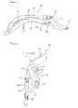
- FIG. 1 is a front perspective view of a vehicle body frame of a motorcycle according to an embodiment of the present invention
- FIG. 2 is a front view of a core according to the embodiment of the present invention.
- FIG. 3 is a view as viewed in the direction indicated by an arrow X in FIG. 2 ;
- FIG. 4 is a view as viewed in the direction indicated by an arrow Y in FIG. 2 ;
- FIG. 5 is a cross-sectional explanatory view schematically showing a mold together with the core in a half opened state
- FIG. 6 is a cross-sectional explanatory view showing a mold clamped state in FIG. 5 ;
- FIG. 7 is a side view of a die-cast product which is taken out after mold clamping in FIG. 5 ;
- FIG. 8 is an end surface view of a splint of the core
- FIG. 9 is a side view of the splint of the core.
- FIG. 10 is a front view of the splint of the core
- FIG. 11 is a cross-sectional view of the mold as viewed from a set-pin arrangement portion side;
- FIG. 12 is a back view of the core
- FIG. 13 is a cross-sectional view of the mold in which a core-hold-pin arrangement portion is viewed in the Z direction in FIG. 2 ;
- FIG. 14 is a enlarged cross-sectional view of a portion A in FIG. 13 .
- a vehicle body frame 1 of a motorcycle includes a main frame 3 which is contiguously formed with a head pipe 2 , and the vehicle body frame 1 is formed of a hollow die-cast product made of light-weight metal such as aluminum or aluminum alloy molded by high-pressure die-casting.
- a pair of left and right main frames 3 , 3 is connected to the head pipe 2 , and pivot plates 4 , 4 which extend downwardly are connected to rear end portions of the respective main frames 3 .
- Engine hangers 5 extend obliquely downwardly from the head pipe 2 , and the engine hangers 5 are connected with the main frames 3 by side wall portions 6 . Opening portions 7 for introducing air are formed in the side wall portions 6 .
- support frames 8 which extend obliquely in the rearward and upward direction and are merged with the main frames 3 , 3 are connected. Portions which range from front ends of the main frames 3 to front sides of upper end portions of the pivot plates 4 are formed into a hollow shape by the aluminum die-cast product, and the pivot plates 4 are joined to the aluminum die-cast product by welding.
- FIG. 2 to FIG. 4 show a core 20 which is used in molding the vehicle body frame 1 using a mold.
- the core 20 serves to form an inner space of the die-cast product 11 which constitutes a portion of the vehicle body frame 1 , wherein the core 20 is constituted of a curved main frame portion 12 which forms a hollow portion of the main frame 3 , a side wall portion 13 which forms a hollow portion of the side wall portion 6 , a support frame portion 14 which forms a hollow portion of the support frame 8 , and an engine hanger portion 16 which forms a hollow portion of the engine hanger 5 such that these portions surround a triangular opening portion 15 .
- the core 20 is molded by baking casting sands which are covered with an adhesive agent and is constituted of a core body 21 which constitutes portions corresponding to respective portions of the vehicle body frame 1 , and splints 22 which are mounted on the mold 10 to prevent the floating of the core body 21 .
- the splints 22 are respectively formed in an approximately columnar shape on two portions at an upper portion of a distal end and a rear end surface of the main frame portion 12 , on two portions in the periphery of the opening portion 15 which constitute a lower portion of the main frame portion 12 and a rear portion of the side wall portion 13 , and on one portion around a portion where the opening portion 7 of the vehicle body frame 1 is formed, on one portion at a lower portion of the support frame portion 14 , and on one portion at a front portion of a lower end of the engine hanger portion 16 .
- the splints 22 are set such that all of long-axis directions of elliptical cross-sectional shapes of the respective splints 22 are arranged parallel to each other (see chained lines in FIG. 3 and FIG. 4 ), these splints 22 are arranged parallel to a mold split surface S described later, and the core 20 is set in the mold 10 such that the core 20 is sandwiched by the mold 10 at the time of clamping the mold 10 .
- an arrow indicates a mold removing direction.
- FIG. 5 to FIG. 7 schematically show the core 20 and the mold 10 which uses the core 20 for facilitating the explanation of the present invention.
- the mold 10 is configured such that a movable mold 18 can be advanced to and retracted from a fixed mold 17 .
- a fixed mold molding portion 25 which forms a profile of the vehicle body frame 1 is formed on the fixed mold 17
- a movable mold molding portion 26 which forms the profile of the vehicle body frame 1 is also formed on the movable mold 18 .
- each splint 22 is provided to both end portions and a center portion of the core 20 , wherein these splints 22 are provided for preventing the floating of the core 20 in which a set pin 30 which is provided to the movable mold 18 is inserted.
- each splint 22 is formed in an approximately elliptical cross section, to be more specific, as shown in FIG. 9 , in an elongated oval cross section which forms a flat surface 23 on upper and lower surfaces.
- the respective splints 22 are provided to the core body 21 such that long axes of the respective elliptical shapes are arranged parallel to each other.
- a distal end portion of the splint 22 is formed to exhibit a shape with round corner portions as viewed in a side view as shown in FIG. 9 as well as in a front view as shown in FIG. 10 , while a proximal portion side of the splint 22 is gently contiguously formed with the core body 21 . Then, as shown in FIG. 10 , the core 20 is set in the mold 10 such that the long axes of the elliptical shapes of the splints 22 having such cross-sectional shape are aligned with the mold split surface S.
- the mold 10 is clamped and, thereafter, molten material is filled between the core 20 and the cavity 27 under pressure to obtain the die-cast product 11 shown in FIG. 7 .
- splint holes 28 are formed in portions of the die-cast product 11 which correspond to the splints 22 of the core 20 .
- the set pins 30 for the core 20 are provided to the movable mold 18 along the mold removing direction (indicated by an arrow).
- the set pins 30 are provided for preventing the displacement of the setting of the core 20 and, as shown in FIG. 12 , are provided to a distal end portion of the main frame portion 12 , the vicinity of a joining portion between the main frame portion 12 and the support frame portion 14 , and the vicinity of the joining portion between the support frame portion 14 and the engine hanger portion 16 .
- These set pins 30 surround the opening portion 15 of the core 20 and, at the same time, positions of the splints 22 which are provided in the periphery of the opening portion 15 assume positions which correspond to respective sides to support the core 20 in a well-balanced manner. That is, these set pins 30 are set such that the splints 22 assume the substantially right triangular arrangement on the core 20 .
- a diameter of the set pins 30 is set to a value which falls within a range from 20 mm to 25 mm, for example, and a distal end portion of the set pin 30 has a small diameter and is inserted into a recessed set pin hole 32 formed in the core 20 .
- the set pins 30 form set pin holes 31 in the die-cast product 11
- the set pin holes 31 are formed in the inside of the vehicle body frame 1 which constitutes the die-cast product 11 and hence, the set pin holes 31 are inconspicuous from the outside whereby merchantability is not lowered.
- the set pin holes 31 can be effectively utilized as sand discharge ports.
- the vicinity of the rear end portion of the main frame portion 12 is formed into a blind array and hence, the set pin hole 31 formed in such a portion has a slightly larger diameter for enhancing the sand removal performance compared to the set pin holes 31 formed in other portions.
- core hold pins 40 penetrate the movable mold 18 and the fixed mold 17 parallel to the mold removing direction at positions avoiding the set pin holes 30 . These core hold pins 40 serve to support portions of the core 20 where an interval between the splints 22 is large in place of the splints 22 .
- the core hold pins 40 have a diameter of approximately 8 mm, for example.
- a pair of core hold pins 40 , 40 which are arranged on one straight line from both of the movable mold 18 and the fixed mold 17 which are provided at a position where the core hold pins 40 , 40 stride over the splints 22 which are formed on the front end portion of the main frame portion 12 and the splints 22 which are positioned in the periphery of the opening portion 15 , while a pair of core hold pins 40 , 40 which support an upper portion of the engine hanger portion 16 on one straight line from both of the movable mold 18 and the fixed mold 17 are provided in the same manner.
- each core hold pin 40 is cut at a right angle, and on a portion of the core 20 with which the core hold pin 40 is brought into contact obliquely, as shown in FIG. 14 , a pressing seat 42 which includes a surface 41 perpendicular to the mold removal direction (indicated by an arrow) is formed. Accordingly, the core hold pin 40 forms an opening portion 43 in the die-cast product 11 .
- the set pins 30 provided to the movable mold 18 are inserted into the set pin holes 32 formed in the core 20 and, thereafter, the mold is clamped.
- the core 20 is prevented from being floated in the inside of the mold 10 due to the splints 22 and, at the same time, is stably supported on the movable mold 18 by the set pins 30 which are arranged in a triangular shape.
- the core 20 is also supported by the core hold pins 40 which penetrate the movable mold 18 and the fixed mold 17 and hence, the core 20 can be surely held in the inside of the cavity 27 .
- a plunger 44 shown in FIG. 11 is allowed to advance and, at the same time, the cavity 27 is evacuated by vacuum suction. Simultaneously, a powdery mold removing agent is sprayed in the inside of the cavity 27 .
- the plunger 44 is retracted to allow the supply of the molten material and, subsequently, vacuum suction is performed and the plunger 44 is advanced at a high speed to inject the molten material into the inside of the cavity 27 .
- the mold is opened and the die-cast product 11 is taken out.
- the core 20 is constituted of the core body 21 and the plurality of splints 22 which are mounted on the core body 21 and have an approximately elliptical cross-sectional shape, and the long axis direction of an ellipse of the splint 22 is set parallel to the mold split surface S of the mold 10 .
- the influence of this heat largely appears in the long axis direction which is the longitudinal direction of the splints 22 and the influence of the heat can be suppressed to a small amount in the short-axis direction of the splints 22 which influences the wall thickness of the outer wall of the hollow portion of the die-cast product 11 thus reflecting the positional accuracy of the splints 22 to the mold 10 .
- the vehicle body frame 1 having the highly accurate die-cast product 11 can be manufactured. Further, since the long-axis direction of the splints 22 is set parallel each other, when the core 20 is mold, it is possible to easily perform the measurement of the positional accuracy of the splints 22 thus facilitating the measurement.
- the side surfaces of the splints 22 are formed into the flat surface 23 and all flat surfaces 23 are set parallel to the mold split surface S of the mold 10 and hence, in clamping the molds, it is possible to hold the splints 22 by sandwiching the flat surfaces 23 of the splints 22 on the mold split surface S of the mold 10 by the fixed mold 17 and the movable mold 18 . Accordingly, the core 20 can be set at the accurate position. As a result, it is possible to manufacture the vehicle body frame 1 having the highly accurate die-cast portion.
- the die-cast casting method of this embodiment by manufacturing the die-cast product 11 by sandwiching the core 20 by the fixed mold 17 and the movable mold 18 , it is possible to easily fix the splints 22 by setting the splints 22 at the mold split surface S of the fixed mold 17 and the movable mold 18 and hence, it is possible to easily perform an operation to set the core 20 in the mold 10 .
- the die-cast product 11 which forms the highly accurate hollow portion using such a core 20 in the vehicle body frame 1 around the handle, it is possible to increase the accuracy of size around the handle whereby the optimum handling performance is imparted to the vehicle.
- the vehicle body frame 1 is the light-metal-made vehicle body frame 1 in which the portion of the main frame 3 which is contiguously formed with the head pipe 2 is formed into a hollow shape by the mold 10 using the core 20 , and at least the opening portion 43 for the core hold pin 40 is formed in the vehicle body frame 1 , and the opening portion 43 is formed by penetration parallel to the mold opening direction of the mold 10 and straightly. Accordingly, it is possible to manufacture the vehicle body frame 1 by effectively supporting the core 20 using core hold pins 40 from portions where the opening portions 43 are formed. As a result, a position of a hollow portion which is formed by the core 20 can be accurately ensured and hence, it is possible to make sizes of thicknesses of walls which surround the hollow portion uniform.
- the set-pin hole 31 for holding the core 20 is formed in a die-cast product 11 and hence, it is possible to effectively make use of the set-pin holes 31 as sand discharging ports whereby an operation to discharge sand in the die-cast product 11 can be efficiently performed.
- the present invention is not limited to the above-mentioned embodiment.
- the embodiment is explained by taking the front portion of the vehicle body frame of the motorcycle as an example, the present invention is applicable to a lower portion of the vehicle body frame and other portions which form a hollow portion.
- the present invention is not limited to the motorcycle and is applicable to a case in which a vehicle body frame of any vehicle is molded into a hollow shape using light weight metal.
Landscapes
- Engineering & Computer Science (AREA)
- Mechanical Engineering (AREA)
- Molds, Cores, And Manufacturing Methods Thereof (AREA)
- Automatic Cycles, And Cycles In General (AREA)
Abstract
Description
Claims (11)
Applications Claiming Priority (2)
| Application Number | Priority Date | Filing Date | Title |
|---|---|---|---|
| JP2005346018A JP4619932B2 (en) | 2005-11-30 | 2005-11-30 | Body frame, die cast casting, die casting die, die casting method |
| JP2005-346018 | 2005-11-30 |
Publications (2)
| Publication Number | Publication Date |
|---|---|
| US20070131377A1 US20070131377A1 (en) | 2007-06-14 |
| US7726382B2 true US7726382B2 (en) | 2010-06-01 |
Family
ID=37757216
Family Applications (1)
| Application Number | Title | Priority Date | Filing Date |
|---|---|---|---|
| US11/605,389 Expired - Fee Related US7726382B2 (en) | 2005-11-30 | 2006-11-29 | Vehicle body frame, die-cast product, mold for die-cast product and die-cast method |
Country Status (4)
| Country | Link |
|---|---|
| US (1) | US7726382B2 (en) |
| EP (1) | EP1792674B1 (en) |
| JP (1) | JP4619932B2 (en) |
| DE (1) | DE602006001391D1 (en) |
Cited By (3)
| Publication number | Priority date | Publication date | Assignee | Title |
|---|---|---|---|---|
| US20100155040A1 (en) * | 2006-02-21 | 2010-06-24 | Ingolf Hoffmann | Heat Sink Comprising a Tube Through Which Cooling Medium Flows |
| US9457863B2 (en) | 2014-11-21 | 2016-10-04 | Suzuki Motor Corporation | Motorcycle frame structure |
| US9527544B2 (en) | 2014-06-24 | 2016-12-27 | Suzuki Motor Corporation | Vehicle body frame structure of motorcycle |
Families Citing this family (12)
| Publication number | Priority date | Publication date | Assignee | Title |
|---|---|---|---|---|
| US7950367B2 (en) * | 2007-03-30 | 2011-05-31 | Honda Motor Co., Ltd. | Accelerator position sensor arrangement structure for motorcycle |
| JP5335549B2 (en) * | 2009-05-13 | 2013-11-06 | 川崎重工業株式会社 | Motorcycle main frame and motorcycle body frame |
| US8434546B1 (en) | 2010-03-30 | 2013-05-07 | Honda Motor Co., Ltd. | Casting mold core retention device and method |
| AT510737B1 (en) * | 2010-12-02 | 2013-06-15 | Borbet Austria Gmbh | METHOD FOR PRODUCING A MOLDED WORKPIECE, IN PARTICULAR A CAST WHEEL |
| CN102343418B (en) * | 2011-08-29 | 2013-07-10 | 西安西工大超晶科技发展有限责任公司 | Casting method of three-dimensional flow aluminum alloy impeller casting |
| TWI505961B (en) * | 2014-05-27 | 2015-11-01 | Kwang Yang Motor Co | Locomotive electronic products fixed structure |
| CN108746502A (en) * | 2018-08-09 | 2018-11-06 | 江苏力源金河铸造有限公司 | A kind of split type sand core of engineering machinery rear cover casting |
| JP7326869B2 (en) * | 2019-05-23 | 2023-08-16 | マツダ株式会社 | mold structure |
| CN112935217A (en) * | 2021-01-28 | 2021-06-11 | 台山市中镁科技有限公司 | Magnesium alloy bicycle frame integral forming core-pulling process |
| JP7497690B2 (en) * | 2021-02-04 | 2024-06-11 | トヨタ自動車株式会社 | Casting mold |
| CN115890568A (en) * | 2022-11-23 | 2023-04-04 | 富钛金属科技(昆山)有限公司 | A press-fitting device for die-casting pins |
| CN117961448B (en) * | 2024-03-28 | 2024-06-28 | 山东华瑞驰达电动车有限公司 | Integrated forming device and process for electric vehicle frame |
Citations (13)
| Publication number | Priority date | Publication date | Assignee | Title |
|---|---|---|---|---|
| US4283835A (en) * | 1980-04-02 | 1981-08-18 | United Technologies Corporation | Cambered core positioning for injection molding |
| JPH01101283A (en) | 1987-10-15 | 1989-04-19 | Suzuki Motor Co Ltd | Frame for motorcycle |
| JPH01101282A (en) | 1987-10-13 | 1989-04-19 | Suzuki Motor Co Ltd | Frame for motorcycle |
| JPH01154857A (en) * | 1987-12-11 | 1989-06-16 | Mazda Motor Corp | Core for pressure casting |
| EP0322305A2 (en) | 1987-12-21 | 1989-06-28 | Honda Giken Kogyo Kabushiki Kaisha | Body frame for motor-bicycle |
| JPH01254479A (en) | 1987-12-21 | 1989-10-11 | Honda Motor Co Ltd | Motorcycle body frames and molds |
| US4913217A (en) * | 1989-01-23 | 1990-04-03 | Farley, Inc. | Locators for expendable core in die casting die |
| JPH02251354A (en) | 1989-03-25 | 1990-10-09 | Honda Motor Co Ltd | Casting method and device for motorcycle body frames |
| JPH08309481A (en) | 1995-05-18 | 1996-11-26 | Hino Motors Ltd | Method for assembling mold of cylinder block of engine for vehicle |
| US20010033104A1 (en) | 2000-03-16 | 2001-10-25 | Frank Hummel | Multi-part vehicle wheel |
| JP2004034092A (en) | 2002-07-03 | 2004-02-05 | Honda Motor Co Ltd | Manufacturing method of casting having hollow part |
| US20040094287A1 (en) * | 2002-11-15 | 2004-05-20 | General Electric Company | Elliptical core support and plug for a turbine bucket |
| US7467655B2 (en) * | 2003-07-01 | 2008-12-23 | General Electric Co. | Perimeter-cooled stage 1 bucket core stabilizing device and related method |
Family Cites Families (3)
| Publication number | Priority date | Publication date | Assignee | Title |
|---|---|---|---|---|
| JP2603085B2 (en) * | 1987-10-07 | 1997-04-23 | マツダ株式会社 | Core for casting |
| JPH0299480A (en) * | 1988-10-04 | 1990-04-11 | Honda Motor Co Ltd | Car body frame for motor bicycle and tricycle |
| JPH07269554A (en) * | 1994-03-30 | 1995-10-17 | Hitachi Metals Ltd | Casting connecting rod |
-
2005
- 2005-11-30 JP JP2005346018A patent/JP4619932B2/en not_active Expired - Fee Related
-
2006
- 2006-11-17 DE DE602006001391T patent/DE602006001391D1/en active Active
- 2006-11-17 EP EP06023937A patent/EP1792674B1/en not_active Ceased
- 2006-11-29 US US11/605,389 patent/US7726382B2/en not_active Expired - Fee Related
Patent Citations (13)
| Publication number | Priority date | Publication date | Assignee | Title |
|---|---|---|---|---|
| US4283835A (en) * | 1980-04-02 | 1981-08-18 | United Technologies Corporation | Cambered core positioning for injection molding |
| JPH01101282A (en) | 1987-10-13 | 1989-04-19 | Suzuki Motor Co Ltd | Frame for motorcycle |
| JPH01101283A (en) | 1987-10-15 | 1989-04-19 | Suzuki Motor Co Ltd | Frame for motorcycle |
| JPH01154857A (en) * | 1987-12-11 | 1989-06-16 | Mazda Motor Corp | Core for pressure casting |
| EP0322305A2 (en) | 1987-12-21 | 1989-06-28 | Honda Giken Kogyo Kabushiki Kaisha | Body frame for motor-bicycle |
| JPH01254479A (en) | 1987-12-21 | 1989-10-11 | Honda Motor Co Ltd | Motorcycle body frames and molds |
| US4913217A (en) * | 1989-01-23 | 1990-04-03 | Farley, Inc. | Locators for expendable core in die casting die |
| JPH02251354A (en) | 1989-03-25 | 1990-10-09 | Honda Motor Co Ltd | Casting method and device for motorcycle body frames |
| JPH08309481A (en) | 1995-05-18 | 1996-11-26 | Hino Motors Ltd | Method for assembling mold of cylinder block of engine for vehicle |
| US20010033104A1 (en) | 2000-03-16 | 2001-10-25 | Frank Hummel | Multi-part vehicle wheel |
| JP2004034092A (en) | 2002-07-03 | 2004-02-05 | Honda Motor Co Ltd | Manufacturing method of casting having hollow part |
| US20040094287A1 (en) * | 2002-11-15 | 2004-05-20 | General Electric Company | Elliptical core support and plug for a turbine bucket |
| US7467655B2 (en) * | 2003-07-01 | 2008-12-23 | General Electric Co. | Perimeter-cooled stage 1 bucket core stabilizing device and related method |
Cited By (4)
| Publication number | Priority date | Publication date | Assignee | Title |
|---|---|---|---|---|
| US20100155040A1 (en) * | 2006-02-21 | 2010-06-24 | Ingolf Hoffmann | Heat Sink Comprising a Tube Through Which Cooling Medium Flows |
| US9527544B2 (en) | 2014-06-24 | 2016-12-27 | Suzuki Motor Corporation | Vehicle body frame structure of motorcycle |
| DE102015110085B4 (en) * | 2014-06-24 | 2017-12-14 | Suzuki Motor Corporation | Car body frame structure of a motorcycle |
| US9457863B2 (en) | 2014-11-21 | 2016-10-04 | Suzuki Motor Corporation | Motorcycle frame structure |
Also Published As
| Publication number | Publication date |
|---|---|
| EP1792674A1 (en) | 2007-06-06 |
| EP1792674B1 (en) | 2008-06-04 |
| JP4619932B2 (en) | 2011-01-26 |
| EP1792674A8 (en) | 2007-08-15 |
| JP2007144500A (en) | 2007-06-14 |
| DE602006001391D1 (en) | 2008-07-17 |
| US20070131377A1 (en) | 2007-06-14 |
Similar Documents
| Publication | Publication Date | Title |
|---|---|---|
| US7726382B2 (en) | Vehicle body frame, die-cast product, mold for die-cast product and die-cast method | |
| WO2014112312A1 (en) | Resin vehicle part manufacturing method and resin vehicle part | |
| JP2000033459A (en) | Cylinder head casting mold apparatus and casting core mounting method | |
| EP1922243B1 (en) | Method for assembling a cross-member and an instrument panel, and centering device | |
| US20080006440A1 (en) | Process for manufacturing an injection molded part with integrated flexible printed circuit board | |
| JPH11222152A (en) | Manufacture of automobile suspension member | |
| EP1525935B1 (en) | Cast-in object plate member, partition plate for intake port, intake-port forming sand core and cylinder head | |
| JP2010069510A (en) | Method for manufacturing vehicle body frame, vehicle body frame and vacuum die casting apparatus | |
| JP4398383B2 (en) | Resin heat exchanger and manufacturing method thereof | |
| JP2008297908A (en) | Manufacturing method and manufacturing apparatus for resin intake manifold | |
| JP2019206317A (en) | Resin panel | |
| JP2890353B2 (en) | Air spoiler molding method and molding die apparatus | |
| CN216176419U (en) | Chilling block and special core assembling tool thereof | |
| JPH09216252A (en) | Mold for molding resin mounting bracket | |
| JP4579131B2 (en) | Manufacturing method and mold for body frame for motorcycle | |
| CN216370118U (en) | Sand core structure applied to low-pressure casting hollow auxiliary frame | |
| JP2634548B2 (en) | Injection mold for vehicle bumper | |
| CN209614137U (en) | A kind of air chamber support casting mould | |
| KR20140122450A (en) | Al diecasting mold for manufacturing trunk lid of vehicle | |
| JP2005297031A (en) | Cylinder block casting core | |
| JPH10216917A (en) | Casting method of low melting point alloy core for intake manifold | |
| JP2018202645A (en) | Resin panel and manufacturing method | |
| JP2008101554A (en) | Water jacket core, cylinder block and manufacturing method thereof | |
| JP2000190059A (en) | Combination of closed deck type cylinder block casting device and sand core used for the device | |
| JP2009270493A (en) | Method of manufacturing resin intake manifold |
Legal Events
| Date | Code | Title | Description |
|---|---|---|---|
| AS | Assignment |
Owner name: HONDA MOTOR CO., LTD.,JAPAN Free format text: ASSIGNMENT OF ASSIGNORS INTEREST;ASSIGNORS:SUZUKI, TOSHIMITSU;SEKI, YOSHITAKA;HARIU, JUN;AND OTHERS;REEL/FRAME:018894/0780 Effective date: 20061204 Owner name: HONDA MOTOR CO., LTD., JAPAN Free format text: ASSIGNMENT OF ASSIGNORS INTEREST;ASSIGNORS:SUZUKI, TOSHIMITSU;SEKI, YOSHITAKA;HARIU, JUN;AND OTHERS;REEL/FRAME:018894/0780 Effective date: 20061204 |
|
| STCF | Information on status: patent grant |
Free format text: PATENTED CASE |
|
| FEPP | Fee payment procedure |
Free format text: PAYOR NUMBER ASSIGNED (ORIGINAL EVENT CODE: ASPN); ENTITY STATUS OF PATENT OWNER: LARGE ENTITY |
|
| FPAY | Fee payment |
Year of fee payment: 4 |
|
| MAFP | Maintenance fee payment |
Free format text: PAYMENT OF MAINTENANCE FEE, 8TH YEAR, LARGE ENTITY (ORIGINAL EVENT CODE: M1552) Year of fee payment: 8 |
|
| FEPP | Fee payment procedure |
Free format text: MAINTENANCE FEE REMINDER MAILED (ORIGINAL EVENT CODE: REM.); ENTITY STATUS OF PATENT OWNER: LARGE ENTITY |
|
| LAPS | Lapse for failure to pay maintenance fees |
Free format text: PATENT EXPIRED FOR FAILURE TO PAY MAINTENANCE FEES (ORIGINAL EVENT CODE: EXP.); ENTITY STATUS OF PATENT OWNER: LARGE ENTITY |
|
| STCH | Information on status: patent discontinuation |
Free format text: PATENT EXPIRED DUE TO NONPAYMENT OF MAINTENANCE FEES UNDER 37 CFR 1.362 |
|
| FP | Lapsed due to failure to pay maintenance fee |
Effective date: 20220601 |