US772485A - Phonograph. - Google Patents
Phonograph. Download PDFInfo
- Publication number
- US772485A US772485A US17269903A US1903172699A US772485A US 772485 A US772485 A US 772485A US 17269903 A US17269903 A US 17269903A US 1903172699 A US1903172699 A US 1903172699A US 772485 A US772485 A US 772485A
- Authority
- US
- United States
- Prior art keywords
- mandrel
- arm
- shaft
- frame
- spectacle
- Prior art date
- Legal status (The legal status is an assumption and is not a legal conclusion. Google has not performed a legal analysis and makes no representation as to the accuracy of the status listed.)
- Expired - Lifetime
Links
- 210000005069 ears Anatomy 0.000 description 6
- 238000010276 construction Methods 0.000 description 5
- 230000003028 elevating effect Effects 0.000 description 4
- 208000027418 Wounds and injury Diseases 0.000 description 3
- 230000006378 damage Effects 0.000 description 3
- 208000014674 injury Diseases 0.000 description 3
- 238000012795 verification Methods 0.000 description 2
- 241000320892 Clerodendrum phlomidis Species 0.000 description 1
- 150000001768 cations Chemical class 0.000 description 1
- 230000007547 defect Effects 0.000 description 1
- 230000000881 depressing effect Effects 0.000 description 1
- 239000011521 glass Substances 0.000 description 1
- 229920000136 polysorbate Polymers 0.000 description 1
Images

Classifications
-
- G—PHYSICS
- G11—INFORMATION STORAGE
- G11B—INFORMATION STORAGE BASED ON RELATIVE MOVEMENT BETWEEN RECORD CARRIER AND TRANSDUCER
- G11B25/00—Apparatus characterised by the shape of record carrier employed but not specific to the method of recording or reproducing, e.g. dictating apparatus; Combinations of such apparatus
- G11B25/02—Apparatus characterised by the shape of record carrier employed but not specific to the method of recording or reproducing, e.g. dictating apparatus; Combinations of such apparatus using cylindrical record carriers
Definitions
- Our invention relates to improvements in tecting devices, whereby when the recorder Iphonographs; and our object generally is to or reproducer has been adjusted for working 1o provide details of construction, arrangement, on very'thin blanks or records the use of a and combination of parts by means of which much thicker record or blank will not result 'the apparatus will be vespecially'adapted for4 in injury to the diaphragms, as might other- O commercial vpurposes as an adjunct to the wise be the case.
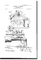
- Figure i is a plan view of our improved comby means of which the position ofthe Diral phonograph, showing the spectaclecorder or reproducer at any part of the record frame, but omitting the usual recorder and remay be noted, whereby any portion of the producer diaphragm-rings; Fig 2, aside view 8O Irecord may be located' in order that correclooking at the machine toward the end gate; vtions therein may be made during transcrip- Fig. 3, a front elevation of a part of the mation, or such portions may be omitted.
- FIG. 6 a perspective vicw 90 carrying separate recorders and reproducers. of the two ,cams wh'ichcomprise part of the This spectacle-frame is so arranged that it repeating mechanism;
- Fig. 7, asectional view may be locked rigidly in position to bring of the elements comprising the repeating the recorder or reproducer in proper relation mechanism, showing the parts in their normal to the record,A while at/the same time it 'can-v position;
- Fig. 8, a similar View showing-the 95 -not be shifted unless the recorder or reprorepeating-lever swung to one side to elevate the spectacle-frame and return the same toward the starting position;
- Fig. 9, a detailed plan view of the parts in position shown in Fig. 8;
- Fig. 10 a View corresponding to Fig. 8',eXcept that the repeating-lever is moved in the oppositedireetion to withdraw the cam and to maintain the spectacle-frame permanently elevated to permit lateral movements thereof.
- the base -plate 1 is provided with cast brackets 2 2. Mounted between said brackets is a stationary back rod 3 and a stationar)7 guide-rod 4. The brackets are also provided with bearings for the feed-shaft 5. Mounted on a stub-shaft 5/, located in one of the brackets 2, is the main driving-pulley 6, (see Fig. 5,) to which power is applied by any suitable form of motor carried beneath the bed-plate 1. Vhen an electric motor is used, it may be controlled from a switch by a button 7.
- the mandrel 8 is much longer than usual and is also preferably somewhat larger in diameter, so as to take a blank of special size and of large capacity.
- the shaft 9 of the mandrel extends entirely through the saine and at its rear end is formed as a cone which bears in a cup formed in the end of the stub-shaft 5. (See Fig. 5.)
- the other end of this shaft is also coned and takes into the bearing-cup 10 on the end gate 11. to one of the brackets 2, as shown, and is formed with a depending lug 12, (see Fig. 2,) with which the friction-spring 18 engages to lock the end gate in its closed position.
- a leaf-spring ⁇ 14 Projecting through an opening in the mandrel 8 is a leaf-spring ⁇ 14, over which the blank is forced and which acts as a friction-latch to prevent the blank from being accidentally displaced.
- the blank cannot be removed from the mandrel without compressing this spring, and the friction thereby imposed on the blank will be sufficient to t'urn it in use even if the blank does not tightly engage the mandrel. This feature prevents records working loose during use and failing to receive dictated matterA before the defect is discovered.
- a pinion '15 Keyed to the mandrel-shaft 9 is a pinion '15, which meshes with and drives the gear 16 on the feed-shaft 5.
- the clutch member 17 is splined to said mandrel-shaft, so as to be movable longitudinally thereon.
- rlhis clutch member is provided with ratchet-teeth which engage corresponding teeth on the hubof the driving-pulley 6, so that when said teeth are in engagement the driving-pulley will rotate the mandrel and feed shaft, as will be This end gate is pivoted" evident.
- the yoke 18 engages the 117h member 17 and is carried by the shaft 19, working in the bearing on the bed-plate 1.
- this shaft 19 At the bottom of this shaft 19 is an arm 2l), which connects by a link 21 with the arni 22 on the rock-shaft 28, mounted in the bearing 24 on the under side of the bed-plate.
- an arm 2l Secured to the other end of this rock-shaft 23 is a small walking-beam 25, whose ends are connected with linger-pieces 26, indicated with the words Stop an( LStart By pressing down on the proper linger-piece the rockshaft will be tilted, so as to swing the clutch into or out of engagement with the d rivingpulley to start or stop the mandrel.
- a lever 27 which may be connected at its ends with a foot-pedal (not shown) and which is adapted to be connected to the rock-shaft 23 by a thumb-screw 28.
- the spring 29 normally retracts the lever 27, so that when the latter is connected with the rock-shaft 223 the spring 29 will normally hold the clutch meinbers out of engagement.
- the clutch members By depressing thel foot-pedal against the tension of the spring 29 the clutch members will he thrown into engagement, so as to drive the mandrel.
- a frame 31 Mounted to slide longitndinallyon the back rod 8 is a frame 31, having an integral east arm 32, which extends up over the rod 4 and is provided with a roller 33, which normally bears on said rod.
- the frame 31 is provided with a leaf-spring 34, carrying ⁇ the feed-nut 35, engaging' the feed-shaft 5 and adjustable by means of' a thumb-screw 36.
- the frame 31 is also provided with an index or pointer 37, which extends over the rod 4 and cooperates with a scale thereon, as shown.
- Pivoted 4to the arm 32 on a horizontal pivot is an arm 38, to which the spectacle-frame 39 is pivoted.
- This spectacle-frame is provided with a thumb-piece 40, by which it may he elevated and swung to one side or the other to bring the recorder or reprodncer into the proper relation with the record or blank.
- the arm 32 is formed at its front edge with a slot or channel 41 therein, with which ears 42 on the spectacle-frame are adapted to engage, so as to center the spectacle-frame, with the recorder or reprodncer in the proper relation.
- Fig. 3 we illustrate one of the ears for the recorder in this engagement, the arm being omitted for the purpose of showing ⁇ the ears 42 and the slot 41.
- the ear 42 By elevating the spectacle-frame so as to swing the arm 38 on ils horizontal pivot the ear 42 will he elevated out of the slot 41, so as to permit the spettacle-frame to be swung out to one side and permit the other ear to engage said slot.
- the spectacle-frame When the spectacle-frame is thus elevated, itis liniloo' ited in its swinging movements bythe pin 43.
- thel neck 49 which is" carried by the lower end of the arm 38, so that the tube 'will be always loca-ted centrally with respect to the recorder orreproducer, whichever may be in operation.
- the reproduction of the work for purposes of verification the speaking-'tube may be used for listening purposes, as will be understood.
- rlhe arm 32 - is formed at one side with a lug 50, in which is mounted the shaft 51 of the repeating mechanism.
- a disk or head 52 On the lower end of this shaft 51'is a disk or head 52, which takes under the'rod 4 and prevents upward movement of the forward end of the arm 32 when the arm 38 is elevated to simultaneously disengage. the recorder or reproducer from the record-surface andv the feed-nut 35 from the feed-shaft.
- rIhe shaft 51 is also provided with a disk 53 thereon, which is located abovetheI rod 4. This disk 53 is formed with a cam 54 When, however, the lugs orv thereon, (see Fig. 6,) andthe lug' 50 is formed with a correspondingcam 55.
- cams 54 and 55 are out of line with one another; but by turning shaft 51 to one side or the other by the lever 56 the two Acams will engage together and result in the elevation of the arm 32 (see Figs. 8 and 10) to lift the spectacle-frame and feed-nut, respectively.
- the spring 57 is coiled around the shaft 51 be- .tween the lug 50 and the lever 56, so as to force the arm 32 downward when the lever 56 is returned to its normal position.
- Pivoted to the under side of the disk 53 is a springactuated pawl 58, adapted ⁇ to engage teeth 59, formed on the side of the bar 4.
- the cams 54 and 55 will not only elevate the arm 32 to disengage the feed-nut ⁇ l35 from the feed-screw, as well as to lift therecorder or reproducer from the record-surface, but immediately after this movement the pawl 58"will engage the teeth '59, so that at the completion of the swinging movementof the lever 56 the entire moving frame, comprising the arm 32, spectacle-frame 39, and frame 31, Will be shifted to the extent of a few threads towardl the starting position, whereupon the reproducer may be engaged with the record to verify the same. If desired", the arm 56 may be given a number of feed movements, as described, so as to carry the recorder or reproducer back to any point on the record that maybe desired.
- Our improved commercial phonograph is provided with a bell 60 of any suitable construction, whose clapper is adapted to been- A speaking-tube (not shown) is applied to gaged by a small gravity-pawl 61, (see Fig. 3,) carried by the frame 31.
- a phonograph the combination with a mandrel and means for rotating the same, of a pivoted end gate, a bearing for the free end of said mandrel carried by said end gateatits free end, and a spring-latch located between said bearing and the pivot of said bearing for automatically locking said end gate in a closed position, said latch being capable of being released by out-ward pressure upon the end gate, substantially as set forth.
- a phonograph the combination with a mandrel-shaft and a mandrel thereon, of a driving-pulley, a stub-shaft carrying said pulley, and which acts as a bearing for one end of said mandrel-shaft, an end gate offering a bearing for theother end of said mandrelshaft. and connections between said drivingpulley and said mandrel-shaft for rotating the latter, substantially as set forth.
- a phonograph the combination with a mandrel-shaft and a mandrel thereon, of a driving-pulley, a stub-shaft carrying said pulley and which acts as abearing for one end of said mandrel-shaft, an end gate offering a bearing for the other end of said mandrelshaft, and clutch connections between said driving-pulley and said mandrel-shaft for rotating the latter, substantially as set forth.
- adriving-shaft in combination, adriving-shaft, a clutch adapted to transmit power from said shaft, and means foroperating said clutch, said means comprising a rock-shaft, a spring-actuated lever, and means for connecting or disconnecting said lever and roch-shaft, substantially as set forth.
- a phonograph the combination with a'mandrel-shaft and mandrel carried thereby, of a rotating driving-lmlley, a clutch member connected to thedriving-shaft and adapted to engage said driving-pulley, a yoke for operating said clutch member, a vertical shaft carrying said yoke, a rock-shaft, connections between said rock-shaft and said vertical shaft, a beam on said rock-shaft ⁇ linger-pieces for actuating said beam ⁇ and a spring-actuated lever normally disconnected from said rock-shaft but adapted to be connected therewith, substantially as and for the purposes set forth.
- a phonograph the combination, with a mandrel, of a rod parallel tothe axis there.- of, a sleeve carried by said rod and movable thereon, a diaphragm-carrier extending ⁇ forward from said sleeve, and a pointer or index extending forward from another portion of said sleeve and cooperating with a stationary scale, substantially as set forth.
- a phonograph the combination of a mandrel, means for rotating the same, a rod supported in the rear of and parallel to said mandrel, a carriage sleeved on said rod, an arm connected to said carriage, a second rod parallel to and between said first rod and mandrel, and supporting the forward end of said arm, an auxiliary arm horizontally pivoted to said iirst arm and projecting forward therefrom, and a spectacle-frame pivoted to said auxiliary arm andoverhanging said mandrel, substantially as set forth.
- a phonograph the combination of a mandrel, means for rotating the same, a rod supported in the rear of and parallel to said mandrel, a carriage sleeved on said rod, an arm connected to said carriage, a second rod parallel to and between said first rod and mandrel and supporting the forward end of said arm, an auxiliary arm horizontally pivoted to said first arm and projecting forward therefrom, a spectacle-frame pivoted to said auxiliary arm and over-hanging said mandrel and means -for adjusting the auxiliary arm, substantially as set forth.
- a phonograph the combination of a mandrel, means for rotating the same, a rod supported in the rear of and ])ara llel to said mandrel, acarriage sleeved on said rod, an arm connected to said carriage, a second rod parallel to and between said irst rod and mandrel and supporting the forward end of said arm, an auxiliary arm horizontally pivoted to said first arm and projecting forward therefrom, a spectacle-frame pivotcd to said auxiliary arm andovcrhanging said mandrel a-nd a tube-supportcarried by the auxiliary arm, substantially as set forth.
- a-phonograph the combination with a mandrel, means for operating the same, and a carriage movable longitudinally with respect to the mandrel, of an arm connected to said carriage, an auxiliary arm horizontally pivoted thereto, a spectacle-frame pivotally carried -by the auxiliary arm, and an interlocking stop device on the spectacle-frame' and firstmentioned arm respectively for locking the spectacle-frame in either of its operative positions, substantially as setvforth.
- a phonograph the combination with a mandrel, means for rotating the same and a carriage movable longitudinally of the mandrel, of a main arm connected to said carriage, an auxiliary arm pivoted to the main arm,- a spectacle-frame pivoted to the auxiliary arm, and two lugs or ears on the spectacle-frame adapted to engage a shoulder or recessin the main arm, substantially as set forth.
- spectacle-frame pivoted to the auxiliary arm, two lugs or'ears on the spectacle-frame adapted to engage a shoulder or recess in the main arm, and means for limiting the movements of the auxiliary arm with respect to the main arm, substantially as set forth.
- a phonograph the combination with a mandrel, means for-rotating the same and a carriage movable longitudinally of the mandrel,'of a main arm connected to said carriage, an auxiliary arm pivoted to the main arm, a spectacle-frame pivoted to the auxiliary arm, two lugs or ears on the spectacle-frame adapted to engage a shoulder or recess in the main arm, and means for limiting the swinging movements of the spectacle-frame, substantially as setv forth.
- a phonograph In a phonograph, the combination with a mandrel, means for rotating the same and a carriage movable longitudinally of the mandrel, of a main arm connected to said carriage, a fixed bar for supporting the free end of said main arm, a repeating-shaft carried by the main arm,;and a cam ⁇ on the repeating-shaft for elevating the main arm when the repeating-shaft is partly rotated, substantially as and for the purposes set forth.
- a phonograph the combination with a mandrel, means for rotating the same and a carriage movable longitudinally of the mandrel, of a main arm connected to said carriage, a fixed bar for supportingthe free end of said main arm, a repeating-shaft carried by the main arm, a cam on the repeating-shaft for elevating the main arm when the repeatingshaft is partly rotated, and means actuated by the repeating-shaft for feeding the main arm longitudinally after the latter has been elevated, substantially as set forth.
- a phonograph the combination with a mandrel, means for rotating the same and a carriage movable longitudinally of the man'- drel, of a main arm connected to said carriage, a fixed bar for supporting the free end of said main arm, a repeating-shaft carried by the main arm, a cam on the repeating-shaft for elevating the main arm when the repeatingshaft is partlyrotated, and a pawl connected to the repeating-shaft and engaging teeth on said bar for feeding the main arm longitudinally after the latter has been elevated, substantially as set forth.
Landscapes
- Grinding And Polishing Of Tertiary Curved Surfaces And Surfaces With Complex Shapes (AREA)
Description
` PATENTED OCT. 18, 1904. P. WEBER & C. L. .HIBBARD.
PHQNOGRAPH. APPLICATION FILED SEPT.10, 1903.
3` SHEETS-SHEET 1.
NO MHDBL.
111 Ven topf I Il liilllli IllmlIllllllllmillliilimll Ilm mmm Alm .111" l m Witnesses PATENTED 00T. 18 1904. P. WEBER 6L C, L. HIBBARD,
PHONGRAPH.
APPLIOATIQN HLBD s211110, 1903.
a sHxmTs-snnt'r a.
VN0 MODEL.
1217er.: tom.
Attorney hief;
.No. 772,485; PATENTED 00118, 1904.
RWEBBR` & C. L. HIBBARD.
PHUNOGRAPH. 'PPLIhATION FILED SEP'LIO, 1903. VNo MODEL.
Witnesses In ventana/ Attorney ,INQ7-72,485, l l' s Patented oeteber 18,1904. UNITED STATES, PATENT OFFICE.
- .PETER WEBER, OF ORANGE, AND CHARLES L. HIBBARD, OF WEST ORANGE, NEW JERSEY, ASSIGNORS TO NEW JERSEY PATENT COMPANY, OF ORANGE, NEW JERSEY, A CORPORATION OF NEW JERSEY.
PHoNoGRAPi-i.
SPECIFICATION forming part of Letters Patent No. 772,485, dated oeteieela 18, 1904. Application filed September l0, 19GB. Serial No. 172,699. (No model.) i
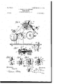
T 017/7/ wwm i?? "my 007%06771" ducer is first elevated clear of the record to Beit known that we, PETER WEBER, residprevent injury to the latter. We alsopro- 50 ing at Orange, and 'CHARLES L. HIBBARD, revide effective adjusting mechanism which sisiding at West Orange, inthe county of Esmultaneously adjusts both the recorder and sex and State of New Jersey, have invented lreproducer vwith respect tov the record to secertain Improvements in Phonographs, of cure the desired perfect operation. We also which the following' is a description. `provide the phonograph with improved pro- V55 Our invention relates to improvements in tecting devices, whereby when the recorder Iphonographs; and our object generally is to or reproducer has been adjusted for working 1o provide details of construction, arrangement, on very'thin blanks or records the use of a and combination of parts by means of which much thicker record or blank will not result 'the apparatus will be vespecially'adapted for4 in injury to the diaphragms, as might other- O commercial vpurposes as an adjunct to the wise be the case. We also provide the appatype-writer. ratus with effective means by which the speclI5 The features of novelty in our improved tacle-frame and feed-nut may be iirst elevated phonograph are hereinafter set forth and and be then returned toward the starting claimed. position to the extent of a few threads, so 05 We provide an improved end gate for supthat by bringing the reproducer into position porting the free end of the mandrel and which any dictated matter can be repeated for puris of simple and effective construction, perposes of verification. This repeating mechmitting the blank to be readily removed and anism is also arranged in such a way as to replaced into position and offering avery permaintain the spectacle-frame and feed-nutin 70 fect bearing'. We also provide an effective an elevatedposition to permit the parts to be starting and stopping device for the mandrel, Y moved back and forth at will. -whereby the vmandrel may be Vstarted and In order that the invention may be better stopped practically instautaneously,and which understood, attention is directed to the accommechanism also permitsv the mandrel to be panying drawings, forming part of this speci- 75 controlledthrough the agency of a foot-pedal. ication, and in which I i We also provide the vphonograph with a scale Figure i is a plan view of our improved comby means of which the position ofthe remercial phonograph, showing the spectaclecorder or reproducer at any part of the record frame, but omitting the usual recorder and remay be noted, whereby any portion of the producer diaphragm-rings; Fig 2, aside view 8O Irecord may be located' in order that correclooking at the machine toward the end gate; vtions therein may be made during transcrip- Fig. 3, a front elevation of a part of the mation, or such portions may be omitted. We chine, showing the mandrel broken away to also provide the improved phonograph with illustrate the bxell mechanism and showing also y a warning-bell'which gives an audible notiithe arm for supporting the spectacle-frame re- 85y cation of the approach of the recorder tomoved, so as to illustrate the alining stopsfor ward the extreme end of the blank in'somethe spectacle-frame; Fig. 4, a sectional view 40 what the same manner as with the ordinary on the line 4 4 of Fig. l; Fig. 5, a sectional type-Writer. Vire' also provide the improved view on the line 5 5 of Fig. l, showing the lphonograph with va novel spectacle-frame for clutch mechanism; Fig. 6, a perspective vicw 90 carrying separate recorders and reproducers. of the two ,cams wh'ichcomprise part of the This spectacle-frame is so arranged that it repeating mechanism; Fig. 7, asectional view may be locked rigidly in position to bring of the elements comprising the repeating the recorder or reproducer in proper relation mechanism, showing the parts in their normal to the record,A while at/the same time it 'can-v position; Fig. 8, a similar View showing-the 95 -not be shifted unless the recorder or reprorepeating-lever swung to one side to elevate the spectacle-frame and return the same toward the starting position; Fig. 9, a detailed plan view of the parts in position shown in Fig. 8; and Fig. 10, a View corresponding to Fig. 8',eXcept that the repeating-lever is moved in the oppositedireetion to withdraw the cam and to maintain the spectacle-frame permanently elevated to permit lateral movements thereof.
v1n all of the above views corresponding parts are represented by the same numerals of reference. V
The base -plate 1 is provided with cast brackets 2 2. Mounted between said brackets is a stationary back rod 3 and a stationar)7 guide-rod 4. The brackets are also provided with bearings for the feed-shaft 5. Mounted on a stub-shaft 5/, located in one of the brackets 2, is the main driving-pulley 6, (see Fig. 5,) to which power is applied by any suitable form of motor carried beneath the bed-plate 1. Vhen an electric motor is used, it may be controlled from a switch by a button 7. The mandrel 8 is much longer than usual and is also preferably somewhat larger in diameter, so as to take a blank of special size and of large capacity. The shaft 9 of the mandrel extends entirely through the saine and at its rear end is formed as a cone which bears in a cup formed in the end of the stub-shaft 5. (See Fig. 5.) The other end of this shaft is also coned and takes into the bearing-cup 10 on the end gate 11. to one of the brackets 2, as shown, and is formed with a depending lug 12, (see Fig. 2,) with which the friction-spring 18 engages to lock the end gate in its closed position. This makes a very simple and effective construction and does away entirely with the necessity for special latches, which have to be first operated before the gate can be opened, as heretofore. The new gate is opened by a simple swinging movement.
Projecting through an opening in the mandrel 8 is a leaf-spring`14, over which the blank is forced and which acts as a friction-latch to prevent the blank from being accidentally displaced. The blank cannot be removed from the mandrel without compressing this spring, and the friction thereby imposed on the blank will be sufficient to t'urn it in use even if the blank does not tightly engage the mandrel. This feature prevents records working loose during use and failing to receive dictated matterA before the defect is discovered.
Keyed to the mandrel-shaft 9 is a pinion '15, which meshes with and drives the gear 16 on the feed-shaft 5. The clutch member 17 is splined to said mandrel-shaft, so as to be movable longitudinally thereon. rlhis clutch member is provided with ratchet-teeth which engage corresponding teeth on the hubof the driving-pulley 6, so that when said teeth are in engagement the driving-pulley will rotate the mandrel and feed shaft, as will be This end gate is pivoted" evident. The yoke 18 engages the ehlteh member 17 and is carried by the shaft 19, working in the bearing on the bed-plate 1. At the bottom of this shaft 19 is an arm 2l), which connects by a link 21 with the arni 22 on the rock-shaft 28, mounted in the bearing 24 on the under side of the bed-plate. Secured to the other end of this rock-shaft 23 isa small walking-beam 25, whose ends are connected with linger-pieces 26, indicated with the words Stop an( LStart By pressing down on the proper linger-piece the rockshaft will be tilted, so as to swing the clutch into or out of engagement with the d rivingpulley to start or stop the mandrel. ln order that the starting and stopping device may be operated by the foot-pedal, we provide a lever 27, which may be connected at its ends with a foot-pedal (not shown) and which is adapted to be connected to the rock-shaft 23 by a thumb-screw 28. The spring 29 normally retracts the lever 27, so that when the latter is connected with the rock-shaft 223 the spring 29 will normally hold the clutch meinbers out of engagement. By depressing thel foot-pedal against the tension of the spring 29 the clutch members will he thrown into engagement, so as to drive the mandrel.
In order to properly support the mandrel when the end gate 11 is open, we extend the mand rel-shaft9 through the bearing-sleeve 30, as heretofore.
Mounted to slide longitndinallyon the back rod 8 is a frame 31, having an integral east arm 32, which extends up over the rod 4 and is provided with a roller 33, which normally bears on said rod. The frame 31 is provided with a leaf-spring 34, carrying` the feed-nut 35, engaging' the feed-shaft 5 and adjustable by means of' a thumb-screw 36. The frame 31 is also provided with an index or pointer 37, which extends over the rod 4 and cooperates with a scale thereon, as shown.
Pivoted 4to the arm 32 on a horizontal pivot is an arm 38, to which the spectacle-frame 39 is pivoted. This spectacle-frame is provided with a thumb-piece 40, by which it may he elevated and swung to one side or the other to bring the recorder or reprodncer into the proper relation with the record or blank. The arm 32 is formed at its front edge with a slot or channel 41 therein, with which ears 42 on the spectacle-frame are adapted to engage, so as to center the spectacle-frame, with the recorder or reprodncer in the proper relation. In Fig. 3 we illustrate one of the ears for the recorder in this engagement, the arm being omitted for the purpose of showing` the ears 42 and the slot 41. By elevating the spectacle-frame so as to swing the arm 38 on ils horizontal pivot the ear 42 will he elevated out of the slot 41, so as to permit the spettacle-frame to be swung out to one side and permit the other ear to engage said slot. When the spectacle-frame is thus elevated, itis liniloo' ited in its swinging movements bythe pin 43.
tliefunder surface of the forward endof the' .arm 32, as willbeunderstood, Fig. 4. 'We
also make use of an adjusting-screw 47, which `passes through the arm 38 and vengages the arm 32, so astoregulate the position of the spectacle-frame with respect. to the record or blank and secure the proper engagement of the recorder or reproducer therewith. This adjustment 1s important in' commercial machines, vsince records will be shaved many times, and hence will vary considerably in thickness.
'If these lugs were not used, there would be danger of injury to the diaphragms inr casev the device had been adjusted for use with a very thin record or blank and was then used without readjustment on a much thicker record or blank, since the adjustability of the strain.
frame should bealways adjusted bythe screw` kcompensating weight would not be suilicient to accommodate such a difference, and in con-l sequence the entire weight of the spectacleframe would be imposed on one of the glass diaphragms. stops 48 are used, one or the other will engage the record or blank before the compensating weight has moved to its eXtreme limit, so as to thereby relieve the diaphragms of any Of course in practice the spectacle- 47, so as to keep the lugsv or stops clear of the recording-surface, and said lugs therefore act' as convenient gages fromwhich to'determine the extent of adjustment necessary.
thel neck 49, which is" carried by the lower end of the arm 38, so that the tube 'will be always loca-ted centrally with respect to the recorder orreproducer, whichever may be in operation. In; the reproduction of the work for purposes of verification the speaking-'tube may be used for listening purposes, as will be understood.
rlhe arm 32 -is formed at one side with a lug 50, in which is mounted the shaft 51 of the repeating mechanism. On the lower end of this shaft 51'is a disk or head 52, which takes under the'rod 4 and prevents upward movement of the forward end of the arm 32 when the arm 38 is elevated to simultaneously disengage. the recorder or reproducer from the record-surface andv the feed-nut 35 from the feed-shaft. rIhe shaft 51 is also provided with a disk 53 thereon, which is located abovetheI rod 4. This disk 53 is formed with a cam 54 When, however, the lugs orv thereon, (see Fig. 6,) andthe lug' 50 is formed with a correspondingcam 55. Normally these cams 54 and 55 are out of line with one another; but by turning shaft 51 to one side or the other by the lever 56 the two Acams will engage together and result in the elevation of the arm 32 (see Figs. 8 and 10) to lift the spectacle-frame and feed-nut, respectively. The spring 57 is coiled around the shaft 51 be- .tween the lug 50 and the lever 56, so as to force the arm 32 downward when the lever 56 is returned to its normal position. Pivoted to the under side of the disk 53 is a springactuated pawl 58, adapted `to engage teeth 59, formed on the side of the bar 4. When the lever 56 is moved to the position lshown in Fig. 8, the cams 54 and 55 will not only elevate the arm 32 to disengage the feed-nut`l35 from the feed-screw, as well as to lift therecorder or reproducer from the record-surface, but immediately after this movement the pawl 58"will engage the teeth '59, so that at the completion of the swinging movementof the lever 56 the entire moving frame, comprising the arm 32, spectacle-frame 39, and frame 31, Will be shifted to the extent of a few threads towardl the starting position, whereupon the reproducer may be engaged with the record to verify the same. If desired", the arm 56 may be given a number of feed movements, as described, so as to carry the recorder or reproducer back to any point on the record that maybe desired. When, however, the arm 56v isv moved in the opposite direction, the cams 54 and 55 will elevate the arm 32; but the pawlv 58 will be carried away from the teeth 59, (see Fig. 10,)so as to per'- mit the parts to be moved freely back and forth, since the feed-nut 35 will be` clear of the feed-screw and the recorder or reproducer will be clear of the record-surface.
Our improved commercial phonograph is provided with a bell 60 of any suitable construction, whose clapper is adapted to been- A speaking-tube (not shown) is applied to gaged by a small gravity-pawl 61, (see Fig. 3,) carried by the frame 31. -By this' construction as the spectacle-frame moves toward the' rear end of the record-surface vthe pawl 61 will engage the bell-clapper, so as to move the latter and permit it to be subsequently released as the pawl progresses in its move- The general operation of the device has IOO already been indicated with suliicient fullness to be understood in connection with the description of its several parts, it being understood, of course, that any approved arrangement of recorder and reproducer is used in connection with the spectacle-frame.
Having now described our invention, what we claim as new therein, and desire to secure by Letters Patent, is as follows:
l. In a phonograph, the combination with a mandrel and means for rotating the same, of an end gate offering a bearing for the free end of said mandrel, and aspring-latch for automatically locking the said end gate in a closed position, said latch being capable of being released by outward pressure upon the end gate, substantially as set forth.
2. In a phonograph, the combination with a mandrel and means for rotatingthe same, of a pivoted end gate offering'a bearing for the free end of said mandrel, and means for locking said end gate located between its pivot and the bearing for said mandrel, said means being capable of being released by outward pressure upon the end gate, substantially as set forth.
3. In a phonograph, the combination with a mandrel and means for rotating the same, of a pivoted end gate, a bearing for the free end of said mandrel carried by said end gate at its free end, and means for locking said end gate ina closed position, said means being capable of being released by outward pressure upon the end gate, substantially as set forth.
4. In a phonograph, the combination with a mandrel and means for rotating the same, of a pivoted end gate, a bearing for the free end of said mandrel carried by said end gateatits free end, and a spring-latch located between said bearing and the pivot of said bearing for automatically locking said end gate in a closed position, said latch being capable of being released by out-ward pressure upon the end gate, substantially as set forth.
5. In a phonograph, the combination with a mandrel-shaft and a mandrel thereon, of a driving-pulley, a stub-shaft carrying said pulley, and which acts as a bearing for one end of said mandrel-shaft, an end gate offering a bearing for theother end of said mandrelshaft. and connections between said drivingpulley and said mandrel-shaft for rotating the latter, substantially as set forth.
6. In a phonograph, the combination with a mandrel-shaft and a mandrel thereon, of a driving-pulley, a stub-shaft carrying said pulley and which acts as abearing for one end of said mandrel-shaft, an end gate offering a bearing for the other end of said mandrelshaft, and clutch connections between said driving-pulley and said mandrel-shaft for rotating the latter, substantially as set forth.
7 In aphonograph, in combination, adriving-shaft, a clutch adapted to transmit power from said shaft, and means foroperating said clutch, said means comprising a rock-shaft, a spring-actuated lever, and means for connecting or disconnecting said lever and roch-shaft, substantially as set forth.
8. In a phonograph, the combination with a'mandrel-shaft and mandrel carried thereby, of a rotating driving-lmlley, a clutch member connected to thedriving-shaft and adapted to engage said driving-pulley, a yoke for operating said clutch member, a vertical shaft carrying said yoke, a rock-shaft, connections between said rock-shaft and said vertical shaft, a beam on said rock-shaft` linger-pieces for actuating said beam` and a spring-actuated lever normally disconnected from said rock-shaft but adapted to be connected therewith, substantially as and for the purposes set forth.
9. In a phonograph, the combination, with a mandrel, of a rod parallel tothe axis there.- of, a sleeve carried by said rod and movable thereon, a diaphragm-carrier extending` forward from said sleeve, and a pointer or index extending forward from another portion of said sleeve and cooperating with a stationary scale, substantially as set forth.
l0. In a phonograph, the combination of a mandrel, means for rotating the same, a rod supported in the rear of and parallel to said mandrel, a carriage sleeved on said rod, an arm connected to said carriage, a second rod parallel to and between said first rod and mandrel, and supporting the forward end of said arm, an auxiliary arm horizontally pivoted to said iirst arm and projecting forward therefrom, and a spectacle-frame pivoted to said auxiliary arm andoverhanging said mandrel, substantially as set forth.
Il. In a phonograph, the combination of a mandrel, means for rotating the same, a rod supported in the rear of and parallel to said mandrel, a carriage sleeved on said rod, an arm connected to said carriage, a second rod parallel to and between said first rod and mandrel and supporting the forward end of said arm, an auxiliary arm horizontally pivoted to said first arm and projecting forward therefrom, a spectacle-frame pivoted to said auxiliary arm and over-hanging said mandrel and means -for adjusting the auxiliary arm, substantially as set forth.
l2. In a phonograph, the combination of a mandrel, means for rotating the same, a rod supported in the rear of and ])ara llel to said mandrel, acarriage sleeved on said rod, an arm connected to said carriage, a second rod parallel to and between said irst rod and mandrel and supporting the forward end of said arm, an auxiliary arm horizontally pivoted to said first arm and projecting forward therefrom, a spectacle-frame pivotcd to said auxiliary arm andovcrhanging said mandrel a-nd a tube-supportcarried by the auxiliary arm, substantially as set forth.
I3. In a phonograph, the combination of a mandrel, means for rotating the same, and Ia IOO llO
carriage movable longitudinally of the mandrel, of a main arm connected to said carriage, an auxiliary arm pivoted to the main arm, a spectacle-frame pivoted to the auxiliary arm and a device on the spectacle-frame which is interlocled with the main arm when the spectacle-frame is in operative-position and which is released when the auxiliary arm is raised on its pivot, substantially as set forth..
. 14. In a-phonograph,the combination with a mandrel, means for operating the same, and a carriage movable longitudinally with respect to the mandrel, of an arm connected to said carriage, an auxiliary arm horizontally pivoted thereto, a spectacle-frame pivotally carried -by the auxiliary arm, and an interlocking stop device on the spectacle-frame' and firstmentioned arm respectively for locking the spectacle-frame in either of its operative positions, substantially as setvforth.
15. In a phonograph, the combination with a mandrel, means for rotating the same and a carriage movable longitudinally of the mandrel, of a main arm connected to said carriage, an auxiliary arm pivoted to the main arm,- a spectacle-frame pivoted to the auxiliary arm, and two lugs or ears on the spectacle-frame adapted to engage a shoulder or recessin the main arm, substantially as set forth.
16. In a phonograph, the combination with a mandrel, means for rotating the same anda carriage movable longitudinally of the mandrel, of a main arm connected to said carriage,
an auxiliary arm pivoted to the main arm, a
spectacle-frame pivoted to the auxiliary arm, two lugs or'ears on the spectacle-frame adapted to engage a shoulder or recess in the main arm, and means for limiting the movements of the auxiliary arm with respect to the main arm, substantially as set forth.
17. In a phonograph, the combination with a mandrel, means for-rotating the same and a carriage movable longitudinally of the mandrel,'of a main arm connected to said carriage, an auxiliary arm pivoted to the main arm, a spectacle-frame pivoted to the auxiliary arm, two lugs or ears on the spectacle-frame adapted to engage a shoulder or recess in the main arm, and means for limiting the swinging movements of the spectacle-frame, substantially as setv forth. I 18. In a phonograph, the combination with a mandrel, means for rotating the same and a carriage movable longitudinally of the mandrel, of a main arm connected to said carriage, a fixed bar for supporting the free end of said main arm, a repeating-shaft carried by the main arm,;and a cam` on the repeating-shaft for elevating the main arm when the repeating-shaft is partly rotated, substantially as and for the purposes set forth.
19; In a phonograph, the combination with a mandrel, means for rotating the same and a carriage movable longitudinally of the mandrel, of a main arm connected to said carriage, a fixed bar for supportingthe free end of said main arm, a repeating-shaft carried by the main arm, a cam on the repeating-shaft for elevating the main arm when the repeatingshaft is partly rotated, and means actuated by the repeating-shaft for feeding the main arm longitudinally after the latter has been elevated, substantially as set forth.
20. In a phonograph, the combination with a mandrel, means for rotating the same and a carriage movable longitudinally of the man'- drel, of a main arm connected to said carriage, a fixed bar for supporting the free end of said main arm, a repeating-shaft carried by the main arm, a cam on the repeating-shaft for elevating the main arm when the repeatingshaft is partlyrotated, and a pawl connected to the repeating-shaft and engaging teeth on said bar for feeding the main arm longitudinally after the latter has been elevated, substantially as set forth.
This specification signed and witnessed this 2d day of September, 1903.
PETER WEBER. CHAS. L. HIBBARD.
Witnesses:
` FRANK L..DYER,
WILLIAM A. DoLAN
Priority Applications (1)
| Application Number | Priority Date | Filing Date | Title |
|---|---|---|---|
| US17269903A US772485A (en) | 1903-09-10 | 1903-09-10 | Phonograph. |
Applications Claiming Priority (1)
| Application Number | Priority Date | Filing Date | Title |
|---|---|---|---|
| US17269903A US772485A (en) | 1903-09-10 | 1903-09-10 | Phonograph. |
Publications (1)
| Publication Number | Publication Date |
|---|---|
| US772485A true US772485A (en) | 1904-10-18 |
Family
ID=2840970
Family Applications (1)
| Application Number | Title | Priority Date | Filing Date |
|---|---|---|---|
| US17269903A Expired - Lifetime US772485A (en) | 1903-09-10 | 1903-09-10 | Phonograph. |
Country Status (1)
| Country | Link |
|---|---|
| US (1) | US772485A (en) |
-
1903
- 1903-09-10 US US17269903A patent/US772485A/en not_active Expired - Lifetime
Similar Documents
| Publication | Publication Date | Title |
|---|---|---|
| US772485A (en) | Phonograph. | |
| US2725235A (en) | Automatic phonograph | |
| US1291515A (en) | Recording attachment. | |
| US423039A (en) | Phonograph for dolls or | |
| US2254839A (en) | Phonographic apparatus | |
| US1027350A (en) | Talking-machine. | |
| US1188728A (en) | Talking-machine and attachment therefor. | |
| US2548831A (en) | Dictating machine | |
| US1537971A (en) | Adding and listing machine | |
| US600315A (en) | Self and joseph a | |
| US876006A (en) | Phonograph and other sound-producing machine. | |
| US1299768A (en) | Phonograph or talking-machine. | |
| US640367A (en) | Talking-machine. | |
| US1158917A (en) | Machine for recording and reproducing sound. | |
| US495990A (en) | Machine for winding sewing-machine bobbins | |
| US732292A (en) | Sound-reproducing machine. | |
| US1111716A (en) | Sound-reproducing machine. | |
| US631912A (en) | Automatic gramophone. | |
| US727002A (en) | Phonograph. | |
| US744267A (en) | Phonographic repeating mechanism. | |
| US999645A (en) | Phonograph. | |
| US685712A (en) | Sound-reproducing apparatus. | |
| US1241956A (en) | Sound-producing apparatus. | |
| US771851A (en) | Repeating attachment for phonographs. | |
| US937905A (en) | Phonograph. |