US7724507B2 - Arc flash enclosure - Google Patents
Arc flash enclosure Download PDFInfo
- Publication number
- US7724507B2 US7724507B2 US11/552,375 US55237506A US7724507B2 US 7724507 B2 US7724507 B2 US 7724507B2 US 55237506 A US55237506 A US 55237506A US 7724507 B2 US7724507 B2 US 7724507B2
- Authority
- US
- United States
- Prior art keywords
- enclosure
- enclosure unit
- door
- switch
- handle
- Prior art date
- Legal status (The legal status is an assumption and is not a legal conclusion. Google has not performed a legal analysis and makes no representation as to the accuracy of the status listed.)
- Active, expires
Links
- 239000002184 metal Substances 0.000 claims description 4
- 208000027418 Wounds and injury Diseases 0.000 description 1
- 230000006378 damage Effects 0.000 description 1
- 238000004880 explosion Methods 0.000 description 1
- 208000014674 injury Diseases 0.000 description 1
- 238000013024 troubleshooting Methods 0.000 description 1
- 238000011144 upstream manufacturing Methods 0.000 description 1
Images


Classifications
-
- H—ELECTRICITY
- H02—GENERATION; CONVERSION OR DISTRIBUTION OF ELECTRIC POWER
- H02B—BOARDS, SUBSTATIONS OR SWITCHING ARRANGEMENTS FOR THE SUPPLY OR DISTRIBUTION OF ELECTRIC POWER
- H02B1/00—Frameworks, boards, panels, desks, casings; Details of substations or switching arrangements
- H02B1/26—Casings; Parts thereof or accessories therefor
- H02B1/28—Casings; Parts thereof or accessories therefor dustproof, splashproof, drip-proof, waterproof or flameproof
-
- Y—GENERAL TAGGING OF NEW TECHNOLOGICAL DEVELOPMENTS; GENERAL TAGGING OF CROSS-SECTIONAL TECHNOLOGIES SPANNING OVER SEVERAL SECTIONS OF THE IPC; TECHNICAL SUBJECTS COVERED BY FORMER USPC CROSS-REFERENCE ART COLLECTIONS [XRACs] AND DIGESTS
- Y10—TECHNICAL SUBJECTS COVERED BY FORMER USPC
- Y10T—TECHNICAL SUBJECTS COVERED BY FORMER US CLASSIFICATION
- Y10T292/00—Closure fasteners
- Y10T292/31—Hasps
- Y10T292/323—Swinging catch
Definitions
- This invention relates to the field of electrical enclosures, and more specifically to an enclosure designed to protect against arc flashes.
- Electrical enclosures can be used to house assorted electrical and datacom equipment.
- the enclosure protects the electrical equipment from the environment and helps prevent access to the equipment.
- the majority of enclosures need the power entering the enclosure to be turned off at a disconnect switch or circuit breaker before the enclosure can be opened.
- some enclosures do need to be accessed with the power still on (e.g., for troubleshooting). Both of these scenarios can still lead to a dangerous situation due to live circuits still being present in the enclosure.
- live circuits are present upstream of the disconnect switch/circuit breaker.
- a short due to human error or other circumstances can lead to an explosion, known as an “arc flash” event, and can lead to major injury or death.
- An enclosure assembly includes a first enclosure unit including a first door and a second enclosure unit.
- a handle is coupled to the second enclosure unit with the handle being operative so as to turn on or turn off power to the first enclosure unit.
- the first enclosure unit and the second enclosure unit are configured such that the first door cannot be opened if the handle has not been turned to a power-off position.
- FIG. 1 shows a perspective view of an enclosure assembly according to one embodiment.
- FIG. 2 a perspective view of the enclosure assembly of FIG. 1 .
- FIG. 3 shows a front view of the enclosure assembly of FIG. 1 .
- FIG. 4 shows details of a latch assembly for the enclosure assembly, in accordance with one embodiment.
- FIG. 5 shows details of a latch assembly for the enclosure assembly, in accordance with one embodiment.
- FIG. 6 shows an enclosure assembly, in accordance with one embodiment.
- FIG. 7 shows an enclosure assembly, in accordance with one embodiment.
- FIG. 1 shows a perspective view of an enclosure assembly 100 according to one embodiment.
- FIG. 2 shows the same view of enclosure assembly 100 with the doors removed to show further details.
- enclosure assembly 100 includes a first enclosure unit 110 including a first door 120 and a second enclosure unit 130 including a second door 140 .
- first enclosure unit 110 includes a metal box defining a back wall, four side walls and front door 120
- second enclosure unit 130 includes a metal box defining a back wall, four side walls, and front door 140 .
- First enclosure 110 is designed to hold electrical equipment such as relays, wires, switches, and contacts, for example.
- a hand-operable handle 150 is coupled to the second enclosure unit 130 .
- Handle 150 is a switch handle and a component of a switch 155 .
- Switch 155 includes handle 150 and switch contacts 158 , which are schematically shown in FIG. 2 .
- Switch contacts 158 are located entirely within enclosure unit 130 . Thus, if a there is an arc flash within enclosure unit 130 , it does not affect anything in enclosure unit 110 .
- Switch handle 150 is operable to turn off and on switch contacts 158 .
- switch 155 can be a typical disconnect switch.
- Power enters second enclosure 130 by electrical lines 132 . Lines 132 are operatively coupled to the switch contacts 158 , and lines 132 then enter first enclosure 110 through a hole 122 located in the side walls of enclosures 120 and 130 .
- switch 155 is configured such that the door 120 of the first enclosure unit 110 cannot be opened unless switch 155 is turned to a power-off position.
- an interlock latch mechanism 210 can be configured in the enclosure assembly 100 .
- Latch mechanism 210 includes a first bar 212 that is operatively coupled to handle 150 and is configured to allow door 120 to be opened if handle 150 is turned to an off position and latches the door if the handle is turned to an on position.
- latch mechanism 210 includes a second bar 214 that operatively coupled to handle 150 and is configured to allow door 140 to be opened if handle 150 is turned to an off position and latches the door if the handle is turned to an on position.
- bars 212 and 214 can be ends of a single bar extending between enclosures 110 and 130 .
- handle 150 of switch 155 is operative so as to turn on or turn off power to first enclosure unit 110 with the contacts 158 of the switch 155 located external to first enclosure unit 110 .
- first enclosure unit 110 and second enclosure unit 130 are configured such that the first door 120 is latched shut by latch mechanism 210 and cannot be opened if the handle 150 (and thus switch 155 ) has not been turned to an off position.
- the switch 155 and contacts 158 are in a separate enclosure than the main enclosure 110 . This means that no current is allowed to enter the first enclosure unit 110 once handle 150 is turned to the off position. This eliminates the arc flash potential in enclosure unit 110 since the first door 120 cannot be opened unless the handle 150 is turned off or the handle 150 is defeated by mechanical means.
- FIG. 3 shows a front view of enclosure assembly 100 .
- Latch mechanism 210 further includes a latch 310 mounted to door 140 of second enclosure unit 130 .
- Latch 310 includes a hooked front end 312 to engage bar 214 when the door 140 is closed.
- latch mechanism 210 can be spring-loaded so that the hooked end 312 can go over the bar 214 if the bar 214 is already in a closed position.
- a similar latch can be attached to the door 120 of first enclosure unit 110 to engage bar 212 .
- FIG. 4 shows a side view of enclosure assembly 100 from inside first enclosure unit 110 , in accordance with one embodiment.
- Bar 212 extends through a slot 402 in the side wall of first enclosure unit 110 .
- the bar is positioned to lock the door of enclosure unit 110 closed.
- the handle 150 is rotated downward, turning the power off, the bar moves so as to unlatch the door of the first enclosure unit 110 .
- FIG. 5 shows a side view of enclosure assembly 100 from inside second enclosure unit 130 , in accordance with one embodiment.
- Handle 150 is mechanically coupled to a linkage 504 to engage and disengage switch contacts 158 of switch 155 .
- latch mechanism 210 further includes a plate 502 that is mechanically coupled or linked to handle 150 .
- Bar 214 extends from plate 502 into second enclosure unit 130 . As handle 150 is rotated upward, the bar 214 is positioned to latch the door of enclosure unit 130 closed. Conversely, when the handle 150 is rotated downward, turning the power off, the bar 214 moves so as to unlatch the door of the second enclosure unit 130 .
- Bar 212 extends from the other side of plate 502 and functions in a similar fashion to latch and unlatch the door of enclosure 110 . In one embodiment, bars 212 and 214 can be ends of a single bar mounted to plate 502 .
- first and second enclosure units 110 and 120 are directly adjacent each other. In some embodiments, the units can be separated by up 2 inches or more, for example
- FIG. 6 shows an enclosure assembly, in accordance with one embodiment.
- a second enclosure unit 630 is encapsulated within a first enclosure unit 610 .
- a handle 650 is used to control switch contacts which are entirely located within enclosure 630 .
- the switch handle 650 is further coupled to a latch mechanism, including bars 652 and 654 . As the switch handle is opened, the bars 654 and 652 move to allow doors 640 and 620 to be opened.
- handles 150 or 650 can be in the form of a rotary handle configured for a rotary switch.
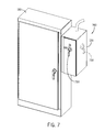
- FIG. 7 shows an enclosure assembly 700 , in accordance with one embodiment.
- enclosure assembly 700 includes first enclosure unit 110 and second enclosure unit 130 , as discussed above.
- a rotary switch including a switch handle 750 is located on the front of the second enclosure unit (or, optionally on the side of the second enclosure unit).
- the switch handle 750 is further coupled to a latch mechanism to keep the door of the first enclosure unit 110 latched until the switch is rotated off.
Landscapes
- Engineering & Computer Science (AREA)
- Power Engineering (AREA)
- Switch Cases, Indication, And Locking (AREA)
Abstract
Description
Claims (15)
Priority Applications (1)
| Application Number | Priority Date | Filing Date | Title |
|---|---|---|---|
| US11/552,375 US7724507B2 (en) | 2006-10-24 | 2006-10-24 | Arc flash enclosure |
Applications Claiming Priority (1)
| Application Number | Priority Date | Filing Date | Title |
|---|---|---|---|
| US11/552,375 US7724507B2 (en) | 2006-10-24 | 2006-10-24 | Arc flash enclosure |
Publications (2)
| Publication Number | Publication Date |
|---|---|
| US20080093932A1 US20080093932A1 (en) | 2008-04-24 |
| US7724507B2 true US7724507B2 (en) | 2010-05-25 |
Family
ID=39317239
Family Applications (1)
| Application Number | Title | Priority Date | Filing Date |
|---|---|---|---|
| US11/552,375 Active 2029-02-04 US7724507B2 (en) | 2006-10-24 | 2006-10-24 | Arc flash enclosure |
Country Status (1)
| Country | Link |
|---|---|
| US (1) | US7724507B2 (en) |
Cited By (13)
| Publication number | Priority date | Publication date | Assignee | Title |
|---|---|---|---|---|
| US8650805B1 (en) * | 2010-05-17 | 2014-02-18 | Equinix, Inc. | Systems and methods for DMARC in a cage mesh design |
| US9236717B2 (en) | 2012-12-11 | 2016-01-12 | Panduit Corp. | Equipment segregation unit for an industrial control panel |
| US10098270B2 (en) | 2012-04-06 | 2018-10-09 | Rockwell Automation Technologies, Inc. | Methods for mitigating arc flash incident energy in motor control devices |
| US10212839B2 (en) | 2016-03-09 | 2019-02-19 | B.S.A.F.E. Manufacturing Incorporated | Risk reduction of electrical hazards |
| US10530133B2 (en) | 2016-03-09 | 2020-01-07 | B.S.A.F.E. Manufacturing Incorporated | Risk reduction of electrical hazards |
| US10811853B2 (en) | 2018-04-30 | 2020-10-20 | Rockwell Automation Technologies, Inc. | Systems and methods for a modular enclosure with a door interlock |
| USD913247S1 (en) * | 2017-02-10 | 2021-03-16 | Eaton Intelligent Power Limited | Electrical apparatus with a line side isolation safety switch |
| US11211776B2 (en) * | 2016-03-09 | 2021-12-28 | B.S.A.F.E. Manufacturing Incorporated | Risk reduction of electrical hazards |
| US11410479B2 (en) | 2019-06-17 | 2022-08-09 | Security Enhancement Systems, Llc | Electronic access control system and method for arc flash prevention |
| US20220385053A1 (en) * | 2020-03-10 | 2022-12-01 | Rodnick Llc | Prefabricated Electrical Module and System |
| US20240022047A1 (en) * | 2020-03-10 | 2024-01-18 | Rodnick Llc | Prefabricated Electrical Module and System |
| US12167550B2 (en) | 2021-05-14 | 2024-12-10 | Hoffman Enclosures Inc. | Disconnect defeater arm mechanism |
| US12283797B2 (en) | 2016-03-09 | 2025-04-22 | B.S.A.F.E. Manufacturing Incorporated | Risk reduction of electrical hazards |
Families Citing this family (2)
| Publication number | Priority date | Publication date | Assignee | Title |
|---|---|---|---|---|
| US8207858B2 (en) * | 2007-08-07 | 2012-06-26 | Cooper Technologies Company | Monitoring systems and methods for ensuring a proper use of personal protective equipment for potential hazards presented to a person while servicing an electrical power system |
| US9318883B2 (en) * | 2012-06-05 | 2016-04-19 | Siemens Industry, Inc. | Sealed doors, enclosures, and methods adapted for use with electrical arc-prone components |
Citations (5)
| Publication number | Priority date | Publication date | Assignee | Title |
|---|---|---|---|---|
| US5515235A (en) * | 1994-11-02 | 1996-05-07 | At&T Corp. | Electrical equipment enclosure including transfer switch and load circuit breaker assembly |
| US6974922B2 (en) * | 2004-03-30 | 2005-12-13 | Rockwell Automation Technologies, Inc. | Rotary service switch for the interior of electrical enclosures having a disconnect switch |
| US20070085347A1 (en) * | 2005-10-13 | 2007-04-19 | Malkowski Chester Jr | Arc resistant electrical enclosure system and method |
| US20090021925A1 (en) * | 2007-07-19 | 2009-01-22 | Qwest Communications International Inc. | Protective telecommunications enclosure systems and methods |
| US20090267466A1 (en) * | 2008-04-28 | 2009-10-29 | Meter Devices Company, Inc. | Primary enclosure for electric power meters |
-
2006
- 2006-10-24 US US11/552,375 patent/US7724507B2/en active Active
Patent Citations (5)
| Publication number | Priority date | Publication date | Assignee | Title |
|---|---|---|---|---|
| US5515235A (en) * | 1994-11-02 | 1996-05-07 | At&T Corp. | Electrical equipment enclosure including transfer switch and load circuit breaker assembly |
| US6974922B2 (en) * | 2004-03-30 | 2005-12-13 | Rockwell Automation Technologies, Inc. | Rotary service switch for the interior of electrical enclosures having a disconnect switch |
| US20070085347A1 (en) * | 2005-10-13 | 2007-04-19 | Malkowski Chester Jr | Arc resistant electrical enclosure system and method |
| US20090021925A1 (en) * | 2007-07-19 | 2009-01-22 | Qwest Communications International Inc. | Protective telecommunications enclosure systems and methods |
| US20090267466A1 (en) * | 2008-04-28 | 2009-10-29 | Meter Devices Company, Inc. | Primary enclosure for electric power meters |
Cited By (17)
| Publication number | Priority date | Publication date | Assignee | Title |
|---|---|---|---|---|
| US8650805B1 (en) * | 2010-05-17 | 2014-02-18 | Equinix, Inc. | Systems and methods for DMARC in a cage mesh design |
| US10098270B2 (en) | 2012-04-06 | 2018-10-09 | Rockwell Automation Technologies, Inc. | Methods for mitigating arc flash incident energy in motor control devices |
| US9236717B2 (en) | 2012-12-11 | 2016-01-12 | Panduit Corp. | Equipment segregation unit for an industrial control panel |
| US11211776B2 (en) * | 2016-03-09 | 2021-12-28 | B.S.A.F.E. Manufacturing Incorporated | Risk reduction of electrical hazards |
| US10212839B2 (en) | 2016-03-09 | 2019-02-19 | B.S.A.F.E. Manufacturing Incorporated | Risk reduction of electrical hazards |
| US10530133B2 (en) | 2016-03-09 | 2020-01-07 | B.S.A.F.E. Manufacturing Incorporated | Risk reduction of electrical hazards |
| US12283797B2 (en) | 2016-03-09 | 2025-04-22 | B.S.A.F.E. Manufacturing Incorporated | Risk reduction of electrical hazards |
| USD942401S1 (en) | 2017-02-10 | 2022-02-01 | Eaton Intelligent Power Limited | Electrical apparatus with a line side isolation safety switch |
| USD913247S1 (en) * | 2017-02-10 | 2021-03-16 | Eaton Intelligent Power Limited | Electrical apparatus with a line side isolation safety switch |
| USD1067885S1 (en) | 2017-02-10 | 2025-03-25 | Eaton Intelligent Power Limited | Electrical apparatus with a line side isolation safety switch |
| US10811853B2 (en) | 2018-04-30 | 2020-10-20 | Rockwell Automation Technologies, Inc. | Systems and methods for a modular enclosure with a door interlock |
| US11410479B2 (en) | 2019-06-17 | 2022-08-09 | Security Enhancement Systems, Llc | Electronic access control system and method for arc flash prevention |
| US20220385053A1 (en) * | 2020-03-10 | 2022-12-01 | Rodnick Llc | Prefabricated Electrical Module and System |
| US11769994B2 (en) * | 2020-03-10 | 2023-09-26 | Rodnick Llc | Prefabricated electrical module and system |
| US20240022047A1 (en) * | 2020-03-10 | 2024-01-18 | Rodnick Llc | Prefabricated Electrical Module and System |
| US12388237B2 (en) * | 2020-03-10 | 2025-08-12 | Rodnick Llc | Prefabricated electrical module and system |
| US12167550B2 (en) | 2021-05-14 | 2024-12-10 | Hoffman Enclosures Inc. | Disconnect defeater arm mechanism |
Also Published As
| Publication number | Publication date |
|---|---|
| US20080093932A1 (en) | 2008-04-24 |
Similar Documents
| Publication | Publication Date | Title |
|---|---|---|
| US7724507B2 (en) | Arc flash enclosure | |
| US7558052B1 (en) | Electrical cabinet assembly and seal assembly therefor | |
| EP2667467B1 (en) | Shutter door assembly for an electrical panel | |
| KR101052671B1 (en) | Power Closed Switchgear | |
| US10991521B2 (en) | Locking device for circuit breaker operation device | |
| CN102725918A (en) | Motor control center and subunit therefor | |
| CN102543511B (en) | Interlock and the regulator cubicle that comprises this interlock | |
| CA2245619C (en) | Multi-door electrical equipment enclosure with mechanical door interlock | |
| JP4515890B2 (en) | Switchboard interlock device | |
| WO2018055829A1 (en) | Switchgear | |
| US8420963B2 (en) | Electrical enclosure apparatus | |
| US20170141549A1 (en) | Electrical Switchgear Manual Safety System and Mechanisms | |
| CN101395775A (en) | Locks for switchgear operating ports | |
| KR102023603B1 (en) | Distribution panel | |
| CN104953496B (en) | Interlock system for baffle | |
| JP2008245334A (en) | Control center | |
| CN205195078U (en) | Operation of haplopore unipolar realizes five miniaturized stationary cabinets of preventing | |
| US20180138671A1 (en) | Cam selector for an earthing switch | |
| CN214849931U (en) | Ventilation system for switchboards | |
| KR102034893B1 (en) | Switchgear | |
| US20160172826A1 (en) | Switch cabinets for use in electrical switchgear and methods of assembling the same | |
| US20220394864A1 (en) | Interlock mechanism for a distribution cabinet | |
| EP3453041B1 (en) | Combination of a panel for accommodating a draw-out device and the draw-out device | |
| JP5344052B2 (en) | Control center | |
| US4728758A (en) | Load break switch and interlock assembly |
Legal Events
| Date | Code | Title | Description |
|---|---|---|---|
| AS | Assignment |
Owner name: HOFFMAN ENCLOSURES INC., MINNESOTA Free format text: ASSIGNMENT OF ASSIGNORS INTEREST;ASSIGNORS:WHITT, JOHN G.;MESSING, KENT G.;KALSTABAKKEN, ROBERT M.;REEL/FRAME:018696/0696 Effective date: 20061220 Owner name: HOFFMAN ENCLOSURES INC.,MINNESOTA Free format text: ASSIGNMENT OF ASSIGNORS INTEREST;ASSIGNORS:WHITT, JOHN G.;MESSING, KENT G.;KALSTABAKKEN, ROBERT M.;REEL/FRAME:018696/0696 Effective date: 20061220 |
|
| STCF | Information on status: patent grant |
Free format text: PATENTED CASE |
|
| FPAY | Fee payment |
Year of fee payment: 4 |
|
| FEPP | Fee payment procedure |
Free format text: MAINTENANCE FEE REMINDER MAILED (ORIGINAL EVENT CODE: REM.) |
|
| FEPP | Fee payment procedure |
Free format text: 7.5 YR SURCHARGE - LATE PMT W/IN 6 MO, LARGE ENTITY (ORIGINAL EVENT CODE: M1555) |
|
| MAFP | Maintenance fee payment |
Free format text: PAYMENT OF MAINTENANCE FEE, 8TH YEAR, LARGE ENTITY (ORIGINAL EVENT CODE: M1552) Year of fee payment: 8 |
|
| MAFP | Maintenance fee payment |
Free format text: PAYMENT OF MAINTENANCE FEE, 12TH YEAR, LARGE ENTITY (ORIGINAL EVENT CODE: M1553); ENTITY STATUS OF PATENT OWNER: LARGE ENTITY Year of fee payment: 12 |