US7722390B2 - Methods and systems for positioning connectors to minimize alien crosstalk - Google Patents
Methods and systems for positioning connectors to minimize alien crosstalk Download PDFInfo
- Publication number
- US7722390B2 US7722390B2 US12/009,635 US963508A US7722390B2 US 7722390 B2 US7722390 B2 US 7722390B2 US 963508 A US963508 A US 963508A US 7722390 B2 US7722390 B2 US 7722390B2
- Authority
- US
- United States
- Prior art keywords
- receptacle
- receptacles
- jacks
- jack
- vertical direction
- Prior art date
- Legal status (The legal status is an assumption and is not a legal conclusion. Google has not performed a legal analysis and makes no representation as to the accuracy of the status listed.)
- Expired - Lifetime
Links
- 238000000034 method Methods 0.000 title abstract description 54
- 239000000463 material Substances 0.000 claims description 8
- 238000002955 isolation Methods 0.000 abstract description 16
- 239000004020 conductor Substances 0.000 description 71
- 230000000694 effects Effects 0.000 description 42
- 230000005540 biological transmission Effects 0.000 description 24
- 230000008878 coupling Effects 0.000 description 22
- 238000010168 coupling process Methods 0.000 description 22
- 238000005859 coupling reaction Methods 0.000 description 22
- 230000013011 mating Effects 0.000 description 20
- 230000001965 increasing effect Effects 0.000 description 18
- 230000007246 mechanism Effects 0.000 description 17
- 238000012360 testing method Methods 0.000 description 12
- 238000006073 displacement reaction Methods 0.000 description 10
- 230000000712 assembly Effects 0.000 description 9
- 238000000429 assembly Methods 0.000 description 9
- 230000008569 process Effects 0.000 description 9
- 230000002829 reductive effect Effects 0.000 description 9
- 230000001808 coupling effect Effects 0.000 description 6
- 238000005259 measurement Methods 0.000 description 6
- 238000010586 diagram Methods 0.000 description 4
- 239000012212 insulator Substances 0.000 description 4
- 230000036961 partial effect Effects 0.000 description 4
- 239000011248 coating agent Substances 0.000 description 3
- 238000000576 coating method Methods 0.000 description 3
- 230000001939 inductive effect Effects 0.000 description 3
- PXHVJJICTQNCMI-UHFFFAOYSA-N Nickel Chemical compound [Ni] PXHVJJICTQNCMI-UHFFFAOYSA-N 0.000 description 2
- 230000002411 adverse Effects 0.000 description 2
- 230000004888 barrier function Effects 0.000 description 2
- 230000001010 compromised effect Effects 0.000 description 2
- 230000003247 decreasing effect Effects 0.000 description 2
- 230000004069 differentiation Effects 0.000 description 2
- 238000009413 insulation Methods 0.000 description 2
- 239000012811 non-conductive material Substances 0.000 description 2
- 239000004033 plastic Substances 0.000 description 2
- OKTJSMMVPCPJKN-UHFFFAOYSA-N Carbon Chemical compound [C] OKTJSMMVPCPJKN-UHFFFAOYSA-N 0.000 description 1
- RYGMFSIKBFXOCR-UHFFFAOYSA-N Copper Chemical compound [Cu] RYGMFSIKBFXOCR-UHFFFAOYSA-N 0.000 description 1
- -1 and Substances 0.000 description 1
- 230000003466 anti-cipated effect Effects 0.000 description 1
- 239000011324 bead Substances 0.000 description 1
- 230000009286 beneficial effect Effects 0.000 description 1
- 229910052799 carbon Inorganic materials 0.000 description 1
- 230000008859 change Effects 0.000 description 1
- 230000000295 complement effect Effects 0.000 description 1
- 229910052802 copper Inorganic materials 0.000 description 1
- 239000010949 copper Substances 0.000 description 1
- 238000011161 development Methods 0.000 description 1
- 230000018109 developmental process Effects 0.000 description 1
- 239000000835 fiber Substances 0.000 description 1
- 239000000945 filler Substances 0.000 description 1
- 231100001261 hazardous Toxicity 0.000 description 1
- 239000000976 ink Substances 0.000 description 1
- 238000003780 insertion Methods 0.000 description 1
- 230000037431 insertion Effects 0.000 description 1
- 238000009434 installation Methods 0.000 description 1
- 238000004519 manufacturing process Methods 0.000 description 1
- 239000002184 metal Substances 0.000 description 1
- 229910052751 metal Inorganic materials 0.000 description 1
- 239000004005 microsphere Substances 0.000 description 1
- 239000000203 mixture Substances 0.000 description 1
- 229910052759 nickel Inorganic materials 0.000 description 1
- 239000003973 paint Substances 0.000 description 1
- 238000012545 processing Methods 0.000 description 1
- 239000007921 spray Substances 0.000 description 1
- 229910001220 stainless steel Inorganic materials 0.000 description 1
- 239000010935 stainless steel Substances 0.000 description 1
Images


Classifications
-
- H—ELECTRICITY
- H01—ELECTRIC ELEMENTS
- H01R—ELECTRICALLY-CONDUCTIVE CONNECTIONS; STRUCTURAL ASSOCIATIONS OF A PLURALITY OF MUTUALLY-INSULATED ELECTRICAL CONNECTING ELEMENTS; COUPLING DEVICES; CURRENT COLLECTORS
- H01R13/00—Details of coupling devices of the kinds covered by groups H01R12/70 or H01R24/00 - H01R33/00
- H01R13/646—Details of coupling devices of the kinds covered by groups H01R12/70 or H01R24/00 - H01R33/00 specially adapted for high-frequency, e.g. structures providing an impedance match or phase match
- H01R13/6461—Means for preventing cross-talk
-
- H—ELECTRICITY
- H01—ELECTRIC ELEMENTS
- H01R—ELECTRICALLY-CONDUCTIVE CONNECTIONS; STRUCTURAL ASSOCIATIONS OF A PLURALITY OF MUTUALLY-INSULATED ELECTRICAL CONNECTING ELEMENTS; COUPLING DEVICES; CURRENT COLLECTORS
- H01R13/00—Details of coupling devices of the kinds covered by groups H01R12/70 or H01R24/00 - H01R33/00
- H01R13/648—Protective earth or shield arrangements on coupling devices, e.g. anti-static shielding
- H01R13/658—High frequency shielding arrangements, e.g. against EMI [Electro-Magnetic Interference] or EMP [Electro-Magnetic Pulse]
- H01R13/6581—Shield structure
- H01R13/6585—Shielding material individually surrounding or interposed between mutually spaced contacts
- H01R13/6586—Shielding material individually surrounding or interposed between mutually spaced contacts for separating multiple connector modules
-
- H—ELECTRICITY
- H01—ELECTRIC ELEMENTS
- H01R—ELECTRICALLY-CONDUCTIVE CONNECTIONS; STRUCTURAL ASSOCIATIONS OF A PLURALITY OF MUTUALLY-INSULATED ELECTRICAL CONNECTING ELEMENTS; COUPLING DEVICES; CURRENT COLLECTORS
- H01R13/00—Details of coupling devices of the kinds covered by groups H01R12/70 or H01R24/00 - H01R33/00
- H01R13/648—Protective earth or shield arrangements on coupling devices, e.g. anti-static shielding
- H01R13/658—High frequency shielding arrangements, e.g. against EMI [Electro-Magnetic Interference] or EMP [Electro-Magnetic Pulse]
- H01R13/6581—Shield structure
- H01R13/659—Shield structure with plural ports for distinct connectors
-
- H—ELECTRICITY
- H01—ELECTRIC ELEMENTS
- H01R—ELECTRICALLY-CONDUCTIVE CONNECTIONS; STRUCTURAL ASSOCIATIONS OF A PLURALITY OF MUTUALLY-INSULATED ELECTRICAL CONNECTING ELEMENTS; COUPLING DEVICES; CURRENT COLLECTORS
- H01R13/00—Details of coupling devices of the kinds covered by groups H01R12/70 or H01R24/00 - H01R33/00
- H01R13/648—Protective earth or shield arrangements on coupling devices, e.g. anti-static shielding
- H01R13/658—High frequency shielding arrangements, e.g. against EMI [Electro-Magnetic Interference] or EMP [Electro-Magnetic Pulse]
- H01R13/6598—Shield material
-
- H—ELECTRICITY
- H01—ELECTRIC ELEMENTS
- H01R—ELECTRICALLY-CONDUCTIVE CONNECTIONS; STRUCTURAL ASSOCIATIONS OF A PLURALITY OF MUTUALLY-INSULATED ELECTRICAL CONNECTING ELEMENTS; COUPLING DEVICES; CURRENT COLLECTORS
- H01R13/00—Details of coupling devices of the kinds covered by groups H01R12/70 or H01R24/00 - H01R33/00
- H01R13/46—Bases; Cases
- H01R13/516—Means for holding or embracing insulating body, e.g. casing, hoods
- H01R13/518—Means for holding or embracing insulating body, e.g. casing, hoods for holding or embracing several coupling parts, e.g. frames
-
- H—ELECTRICITY
- H01—ELECTRIC ELEMENTS
- H01R—ELECTRICALLY-CONDUCTIVE CONNECTIONS; STRUCTURAL ASSOCIATIONS OF A PLURALITY OF MUTUALLY-INSULATED ELECTRICAL CONNECTING ELEMENTS; COUPLING DEVICES; CURRENT COLLECTORS
- H01R13/00—Details of coupling devices of the kinds covered by groups H01R12/70 or H01R24/00 - H01R33/00
- H01R13/58—Means for relieving strain on wire connection, e.g. cord grip, for avoiding loosening of connections between wires and terminals within a coupling device terminating a cable
- H01R13/5804—Means for relieving strain on wire connection, e.g. cord grip, for avoiding loosening of connections between wires and terminals within a coupling device terminating a cable comprising a separate cable clamping part
-
- H—ELECTRICITY
- H01—ELECTRIC ELEMENTS
- H01R—ELECTRICALLY-CONDUCTIVE CONNECTIONS; STRUCTURAL ASSOCIATIONS OF A PLURALITY OF MUTUALLY-INSULATED ELECTRICAL CONNECTING ELEMENTS; COUPLING DEVICES; CURRENT COLLECTORS
- H01R24/00—Two-part coupling devices, or either of their cooperating parts, characterised by their overall structure
- H01R24/60—Contacts spaced along planar side wall transverse to longitudinal axis of engagement
- H01R24/62—Sliding engagements with one side only, e.g. modular jack coupling devices
- H01R24/64—Sliding engagements with one side only, e.g. modular jack coupling devices for high frequency, e.g. RJ 45
-
- Y—GENERAL TAGGING OF NEW TECHNOLOGICAL DEVELOPMENTS; GENERAL TAGGING OF CROSS-SECTIONAL TECHNOLOGIES SPANNING OVER SEVERAL SECTIONS OF THE IPC; TECHNICAL SUBJECTS COVERED BY FORMER USPC CROSS-REFERENCE ART COLLECTIONS [XRACs] AND DIGESTS
- Y10—TECHNICAL SUBJECTS COVERED BY FORMER USPC
- Y10S—TECHNICAL SUBJECTS COVERED BY FORMER USPC CROSS-REFERENCE ART COLLECTIONS [XRACs] AND DIGESTS
- Y10S439/00—Electrical connectors
- Y10S439/941—Crosstalk suppression
Definitions
- the present application is related to applications entitled “CABLE WITH OFFSET FILLER” (U.S. Ser. No. 10/746,800) and “CABLE UTILIZING VARYING LAY LENGTH MECHANISMS TO MINIMIZE ALIEN CROSSTALK” (U.S. Ser. No. 10/746,757), each filed Dec. 26, 2003, and each of which is incorporated by reference in its entirety.
- the present application is also related to applications entitled “METHODS AND SYSTEMS FOR MINIMIZING ALIEN CROSSTALK BETWEEN CONNECTORS” and “METHODS AND SYSTEMS FOR COMPENSATING FOR ALIEN CROSSTALK BETWEEN CONNECTORS”, each filed on the same date as the present application.
- the present invention relates to methods and systems for minimizing alien crosstalk between connectors. Specifically, the methods and systems relate to isolation and compensation techniques for minimizing alien crosstalk between connectors for use with high-speed data cabling.
- communications networks In the field of data communications, communications networks typically utilize techniques designed to maintain or improve the integrity of signals being transmitted via the network (“transmission signals”). To protect signal integrity, the communications networks should, at a minimum, satisfy compliance standards that are established by standards committees, such as the Institute of Electrical and Electronics Engineers (IEEE). The compliance standards help network designers provide communications networks that achieve at least minimum levels of signal integrity as well as some standard of interoperability.
- standards committees such as the Institute of Electrical and Electronics Engineers (IEEE).
- IEEE Institute of Electrical and Electronics Engineers
- crosstalk One obstacle to maintaining adequate levels of signal integrity, known as crosstalk, adversely affects signal integrity by causing capacitive and inductive coupling between the transmission signals. Specifically, electromagnetic interference produced by one transmission signal may couple to another transmission signal and thereby disrupt or interfere with the affected transmission signal. The electromagnetic interference tends to emanate outwardly from a source transmission signal and undesirably affect any sufficiently proximate transmission signal. As a result, crosstalk tends to compromise signal integrity.
- typical communications networks include areas that are especially susceptible to crosstalk because of the proximity of the transmission signals.
- the communications networks include connectors that bring transmission signals into close proximity to one another.
- the conductive pins of a traditional connector such as a jack
- the conductive pins of a traditional connector are placed proximate to one another to form a convenient connection configuration, usually within the compact spaces of the connector. While such compact pin arrangements may be physically economical as a convenient connecting medium, the same pin arrangements tend to produce nightmarish crosstalk between the pins.
- PCB printed circuit board
- Intra-connector techniques for combating crosstalk have helped to satisfactorily maintain the signal integrity of traditional transmission signals.
- the ensuing volumes of data traffic have accentuated the need for communications networks to transmit the data at higher speeds.
- signal integrity is more easily compromised due to increased levels of interference between the high-speed transmission signals carrying the data.
- the effects of crosstalk are magnified because the high-speed signals produce stronger electromagnetic interference levels as well as increased coupling distances.
- the magnified crosstalk associated with high-speed signals can significantly disrupt the transmission signals of conventional network connectors.
- This form of crosstalk known as alien crosstalk, describes the coupling effects between connectors.
- high-speed data signals traveling via a first connector produce electromagnetic interference that couples to high-speed data signals traveling via an adjacent connector, adversely affecting the high-speed data signals of the adjacent jack.
- the magnified alien crosstalk produced by the high-speed signals can easily compromise the integrity of the transmission signals of an adjacent connector. Consequently, the transmission signals may become unrecognizable to a receiving device, and may even be compromised to the point that the transmission signals no longer comply with the established compliance standards.
- Conventional connectors are ill-equipped to protect high-speed signals from alien crosstalk.
- Conventional connectors have largely been able to ignore alien crosstalk when transmitting traditional data signals.
- conventional connectors utilize techniques designed to control intra-connector crosstalk.
- these techniques do not provide adequate levels of isolation or compensation to protect from connector-to-connector alien crosstalk at high transmission speeds.
- such techniques cannot be applied to alien crosstalk, which can be much more complicated to compensate for than is intra-connector crosstalk.
- alien crosstalk comes from a number of unpredictable sources, especially in the context of high-speed signals that typically use more transmission signals to carry the signal's increased bandwidth requirements.
- alien crosstalk is a significant factor for protecting the signal integrity of high-speed signals being transmitted via data communications networks.
- Conventional network connectors cannot effectively and accurately transmit high-speed data signals.
- the conventional connectors for use in unshielded cabling networks do not provide adequate levels of compensation or isolation from alien crosstalk.
- the present invention relates to methods and systems for minimizing alien crosstalk between connectors. Specifically, the methods and systems relate to isolation and compensation techniques for minimizing alien crosstalk between connectors for use with high-speed data cabling.
- a frame can be configured to receive a number of connectors.
- a number of shield structures may be positioned to isolate at least a subset of the connectors from one another.
- the connectors can be positioned to move at least a subset of the connectors away from alignment with a common plane.
- a signal compensator may be configured to adjust a data signal to compensate for alien crosstalk.
- the connectors are configured to efficiently and accurately propagate high-speed data signals by, among other functions, minimizing alien crosstalk.
- FIG. 1 shows a perspective view of a jack assembly according to one embodiment of the invention.
- FIG. 2 shows a perspective view of the frame and the shield structure of FIG. 1 .
- FIG. 3 is a perspective view of a second embodiment of the jack assembly of FIG. 1 .
- FIG. 4 is a perspective view of a shield structure according to the embodiment of FIG. 3 .
- FIG. 5 shows a perspective view of a third embodiment of the jack assembly of FIG. 1 .
- FIG. 6 shows a perspective view of a shield structure according to the embodiment shown in FIG. 5 .
- FIG. 7 is a perspective view of a fourth embodiment of the jack assembly of FIG. 1 .
- FIG. 8 is a perspective view of a shield structure according to the embodiment shown in FIG. 7 .
- FIG. 9 is a perspective view of a fifth embodiment of the jack assembly of FIG. 1 .
- FIG. 10 is a perspective view of a sixth embodiment of the jack assembly of FIG. 1 .
- FIG. 11 is a perspective view of a seventh embodiment of the jack assembly of FIG. 1 .
- FIG. 12 is another perspective view of the jack assembly of FIG. 11 .
- FIG. 13 is a perspective view on a panel having multiple jack assemblies of FIG. 12 .
- FIG. 14 is another perspective view of the panel of FIG. 13 .
- FIG. 15A is a perspective view of a jack having shielded surfaces.
- FIG. 15B is another perspective view of the jack of FIG. 15A .
- FIG. 16A is a perspective view of a shielded termination cap.
- FIG. 16B is another perspective view of the shielded termination cap of FIG. 16A .
- FIG. 17 is a perspective view of an embodiment of a jack assembly with adjacent jacks positioned at different angles with respect to a surface of the jack assembly.
- FIG. 18A is a perspective view of an embodiment of a jack assembly with adjacent jacks positioned at different depths with respect to a surface of the jack assembly.
- FIG. 18B is a side-view of conductors of the staggered jacks of FIG. 18A .
- FIG. 18C shows a top-view of the conductors of the staggered jacks of FIG. 18B .
- FIG. 19A is a perspective view of an embodiment of a jack assembly with adjacent jacks offset from one another.
- FIG. 19B is a side-view of conductors of the jack assembly of FIG. 19A .
- FIG. 19C shows a front-view of the conductors of FIG. 19B .
- FIG. 19D is a front-view of another embodiment of the jack assembly of FIG. 19A .
- FIG. 19E is a front-view of another embodiment of the jack assembly of FIG. 19D .
- FIG. 20A is a perspective view of an embodiment of a jack assembly with adjacent jacks inverted with respect to one another.
- FIG. 20B is a side-view of conductors of the jack assembly of FIG. 20A .
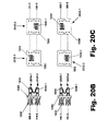
- FIG. 20C is a front-view of the conductors of FIG. 20B .
- FIG. 20D is a front-view of pins of vertically arranged jacks, where one of the jacks is inverted.
- FIG. 21 is a block diagram of an embodiment of a jack assembly for use in determining alien crosstalk between jacks.
- FIG. 22 is a block diagram of a test assembly for determining alien crosstalk between adjacent jacks.
- the present invention relates to methods and systems for minimizing alien crosstalk between connectors. Specifically, the methods and systems relate to isolation and compensation techniques for minimizing alien crosstalk between connectors for use with high-speed data cabling.
- a jack can include but is not limited to a socket for receiving a plug and a number of insulation displacement contacts (IDC) for receiving the insulated conductors of a data cable's twisted pairs.
- IDC insulation displacement contacts
- isolation and compensation techniques for minimizing alien crosstalk.
- An isolation technique is meant to be understood broadly as any system or method that tends to isolate connectors to prevent or at least reduce the effects that the alien crosstalk generated by one connector has on another connector.
- a compensation technique is meant to be understood broadly as any system or method that tends to adjust a data signal to compensate for the coupling effects of alien crosstalk from another connector.
- the present methods and systems contemplate using any combination or subset of isolation and compensation techniques to minimize the effects of alien crosstalk between connectors.
- FIG. 1 shows a perspective view of a jack assembly 100 according to one embodiment of the invention.
- the jack assembly 100 can include a frame 110 and a shield structure 120 .
- the frame 110 forms a number of jack receptacles 130 for receiving jacks 135 .
- the shield structure 120 may include a number of shield sections 140 , which are preferably positioned to separate (i.e., isolate) the received jacks 135 from one another. Such a positioning helps minimize alien crosstalk between the jacks 135 , especially between adjacently positioned jacks 135 .
- the frame 110 is configured to receive and support a number of the jacks 135 .
- the frame 110 can form the jack receptacles 130 for housing the received jacks 135 .
- the jack receptacles 130 should be shaped to fittingly support the received jacks 135 in fixed positions.
- the jack receptacles 130 shown in FIG. 1 comprise walls forming orifices for receiving the jacks 135 .
- the jack receptacles 130 and the jacks 135 are complimentarily shaped to promote secure housing of said jacks 135 in position.
- the frame 110 is not limited to a specific shape or structure.
- the frame 110 can be a variety of different shapes so long as the frame 110 can house the jacks 135 .
- the frame 110 of FIG. 1 comprises a faceplate. In other embodiments, the frame 110 may be shaped differently for use with other structures, such as a patch panel. Some embodiments of the jack assembly 100 discussed below illustrate different shapes of the frame 110 .
- the frame 110 can include mounting structures 160 for mounting the frame 110 to a fixture for support.
- the mounting structures 160 of FIG. 1 include orifices for receiving a screw or other object capable of fixing the frame 110 to a support structure.
- the jacks 135 should be configured to electrically connect two separate electrical conductors together.
- the jack 135 can include insulation displacement contact towers 150 (hereinafter “the IDC towers 150 ”) extending from a surface of the jack 135 to form the IDC's that can receive and establish electrical contact with the insulated conductors of a cable.
- the jack 135 also includes a socket 155 (see FIG. 12 ) having conductors for receiving and establishing electrical contact with a plug.
- the IDC's and the socket 155 conductors of the jack 135 are electrically connected to each other by the jack 135 .
- the jack 135 can establish an electrical connection between the conductors received by the IDC's and the plug received by the socket 155 .
- the jack 135 comprises a recommended jack (RJ), such as an RJ-45 or RJ-48 type jack.
- the shield structure 120 should be positioned to isolate the adjacent jacks 135 from one another, thereby minimizing alien crosstalk between the adjacent jacks 135 . As shown in FIG. 1 , the shield structure 120 can be positioned between the adjacent jacks 135 . Specifically, the shield structure 120 may include any number of the shield sections 140 . The shield sections 140 can be positioned between the adjacent jacks 135 .
- the shield structure 120 isolates the IDC's of the jack 135 from the IDC's of an adjacently positioned jack 135 . This isolation helps minimize the alien crosstalk that can otherwise occur between conductors received by the IDC's of the adjacent jacks 135 .
- the shield structure 120 includes shield sections 140 that are positioned between the IDC's of the adjacent jacks 135 .
- the shield structure 120 should comprise shapes and materials that function to isolate the adjacent jacks 135 .
- the shield structure 120 extends to a height that is substantially the same as or higher than the height of the jacks 135 . This helps reduce alien crosstalk by separating the IDC's of the jacks 135 from one another.
- the shield structure 120 may be a wide variety of different shapes, thickness, and/or sizes, so long as the shield structure 120 helps reduce alien crosstalk between the adjacent jacks 135 .
- the shield structure 120 including the shield sections 140
- the shield structure 120 can be thin for logistical purposes, so long as the shield structure 120 reduces alien crosstalk.
- FIG. 1 illustrates generally planar shield sections 140 extending away from a surface of the frame 110 to separate the adjacent jacks 135 .
- Other embodiments discussed below show some of the alternative configurations of the shield structure 120 that can minimize alien crosstalk between the adjacent jacks 135 .
- the shield structure 120 can be fixed to the frame 110 .
- the shield structure 120 may be permanently part of the frame 110 and extend away from the frame 110 to separate the received jacks 135 .
- the shield structure 120 and the frame 110 are formed from a unitary material, and may be molded.
- the shield structure 120 can be separate from the frame 110 , but configured to be fixed to the frame 110 by some form of securing mechanism, such as a snap-fit mechanism.
- the shield structure 120 can be supported by the jack 135 . Examples of different configurations of the shield structure 120 are discussed in detail below.
- the shield structure 120 can physically separate the adjacent jacks 135 , it can also electrically isolate the adjacent jacks 135 from one another.
- the shield structure 120 should comprise a conductive material that functions to obstruct or minimize the flow of electrical signals away from their intended paths, including the coupling signals of alien crosstalk.
- the conductive material of the shield structure 120 should act as an electrical barrier between the adjacent jacks 135 .
- the conductive material can comprise any material and application form that helps to minimize alien crosstalk.
- the material may include any conductive material, including but not limited to nickel, copper, and conductive paints, inks, and, sprays.
- the shield structure 120 can include conductive shield sections 140 , such as metal-based members, positioned to separate the adjacent jacks 135 .
- the conductive material may include a spray-on coating of conductive material applied to at least a portion of the shield structure 120 .
- the spray-on coating may be applied to a supporting material, such as some type of plastic.
- the shield structure 120 may comprise conductive elements that disrupt alien crosstalk without making the shield structure 120 a conductive structure.
- the shield structure 120 can include a non-conductive material, such as a resinous or plastic material, which is impregnated with conductive elements.
- the conductive elements may include but are not limited to conductive carbon loads, stainless steel fibers, micro-spheres, and plated beads.
- the conductive elements can be positioned such that the shield structure 120 is not conductive. This helps prevent any undesirable short-circuiting with the shield structure 120 .
- the conductive elements should be positioned with sufficient density to disrupt alien crosstalk between adjacent jacks 135 .
- Other members of the jack assembly 100 may include the conductive material to help isolate the jacks 135 .
- the frame 110 can include the conductive elements.
- the jack 135 includes conductive materials.
- the conductive material of the shield structure 120 is not grounded.
- An ungrounded conductive shield structure 120 can function to block or at least disrupt alien crosstalk signals.
- the conductive materials of the shield structure 120 can be sized such that they do not produce harmful capacitances when not grounded.
- the shield structure 120 can isolate the adjacent jacks 135 of unshielded cabling systems, which make up a substantial part of deployed cabling systems. Consequently, the ungrounded shield structure 120 is able to avoid many of the costs, dangers, and hassles that are inherent to a shielded cabling system, including the potentially hazardous effects of a faulty ground connection.
- the conductive materials of the shield structure 120 can be electrically isolated such that they do not interfere with the data signals transmitted via the jacks 135 .
- the shield structure 120 may include an insulator to prevent its conductive materials from making electrical contact with any conductors associated with the jacks 135 .
- the insulator can be applied over the conductive materials of the shield structure 120 .
- the insulator may be any non-conductive material that can be applied to the conductive materials, including a spray-on material. When applied, the insulator is helpful for preventing the conductors of an attached cable from inadvertently shorting via the shield structure 120 . This is especially beneficial when the IDC towers 150 of one jack 135 are positioned proximate to the IDC towers 150 of an adjacent jack 135 .
- the shield structure 120 may be positioned or shaped to keep its conductive materials electrically isolated.
- the shield structure 120 can include thin shield sections 140 configured to fit between the adjacent jacks 135 without electrically contacting cabling conductors that are connected to the IDC's of the jacks 135 .
- FIG. 2 shows a perspective view of the frame 110 and the shield structure 120 of FIG. 1 .
- the shield structure 120 can be permanently fixed to the frame 110 and extend away from the frame 110 at positions between the jack receptacles 130 . Accordingly, the shield structure 120 is positioned to separate the jacks 135 when the jacks 135 have been received by the jack receptacles 130 .
- the shield structure 120 shown in FIG. 2 includes four shield sections 140 , and each shield section 140 is positioned between the adjacent jack receptacles 130 .
- the frame 110 and shield structure 120 shown in FIG. 2 can be conveniently installed in a data network to reduce alien crosstalk, even in an existing data network.
- the frame 110 can be easily substituted for already deployed faceplates or panels, thereby providing the shield structure 120 between the connectors of an existing data network.
- FIG. 3 is a perspective view of a second embodiment of the jack assembly 100 of FIG. 1 .
- the jack assembly 100 - 1 shown in FIG. 3 includes a shield structure 120 - 1 .
- the shield structure 120 - 1 includes the features of the shield structure 120 and further includes a number of outer shield sections 340 positioned along the outer edges of the jacks 135 to shield the jacks 135 from alien crosstalk generated by sources external of the jack assembly 100 - 1 .
- the outer shield sections 340 can isolate the jacks 135 of the jack assembly 100 - 1 from alien crosstalk generated by external jacks of adjacent jack assemblies, which may lack a shield structure 120 - 1 .
- the jacks 135 positioned generally lateral from the jacks 135 of the jack assembly 100 - 1 are of particular concern.
- the outer shield sections 340 are positioned along each outer edge of the jacks 135 , forming a perimeter of outer shield sections 340 about the jacks 135 .
- the outer shield sections 340 should form at least a partial perimeter about the jacks 135 .
- FIG. 4 provides a perspective view of the shield structure 120 - 1 of FIG. 3 .
- the outer shield sections 340 include the same features described above in relation to the shield sections 140 of the shield structure 120 , including the conductive material that functions to obstruct alien crosstalk.
- FIG. 5 shows a perspective view of a third embodiment of the jack assembly 100 of FIG. 1 .
- FIG. 5 shows a jack assembly 100 - 2 that includes a shield structure 120 - 2 inserted between the jack receptacles 130 to separate the received jacks 135 .
- the shield structure 120 - 2 includes the same features of the shield structure 120 . Further, the shield structure 120 - 2 can be configured to fittingly couple to the frame 110 to separate the adjacent jacks 135 . Specifically, the shield structure 120 - 2 includes shield sections 140 - 2 configured to facilitate an easy insertion and/or removal of the shield structure 120 - 2 between the jacks 135 .
- the shield sections 140 - 2 can be arranged in wide variety of ways such that they can be fittingly coupled to the frame 110 and separate the jacks 135 . As shown in FIG. 5 , the shield sections 140 - 2 can be joined together by a joining member 510 such that the shield sections 140 - 2 and the joining member 510 form a generally V-shaped structure.
- the joining member 510 can be any size that provides an optimal distance between the shield sections 140 - 2 so that the shield structure 120 - 2 can be fittingly coupled between the jack receptacles 130 .
- FIG. 6 is a perspective view of the shield structure 120 - 2 , where the distance (d) between the shield sections is indicated. The distance (d) should correspond with a space between the adjacent jack receptacles 135 .
- the joining member 510 also provides stability to the shield structure 120 - 2 .
- the shield structure 120 - 2 should include a structure and/or aperture for coupling to the frame 110 .
- the shield sections 140 - 2 can include coupling apertures 620 for coupling to the frame 110 .
- the coupling apertures 620 are configured to receive complimentary protrusions of the frame 110 to fix the shield structure 120 - 2 at a position between the adjacent jack receptacles 130 .
- the shield sections 140 - 2 in combination with the joining member 510 should have spring-like characteristics.
- the shield structure 120 - 2 is configured to snap-fit to the frame 110 at a position between the adjacent jack receptacles 130 such that when the shield structure 120 - 2 is in its final orientation, the apertures 620 are biased into engagement with their mating male members.
- the shield sections 140 - 2 may include a sloped extension 630 configured to facilitate the coupling of the shield structure 120 - 2 to the frame 110 .
- the sloped extension 630 is configured to help the shield sections 140 - 2 compact together as the shield structure 120 - 2 moves into position to couple to the frame 110 .
- Other mechanisms can be used to fix the shield structure 120 - 2 to the frame 110 so long as the shield structure 120 - 2 is positioned to separate the adjacent jacks 135 from one another.
- the shield structure 120 - 2 can be configured to separate various arrangements of adjacent jacks 135 .
- the shield structure 120 - 2 may be configured to separate four jacks 135 into quadrant regions.
- the shield sections 140 - 2 run parallel to a first axis and separate the four jacks 135 into two areas.
- the shield sections 140 - 2 include slots 640 for receiving a number of the shield sections 140 .
- slots 640 may receive the shield sections 140 such that the shield sections 140 run along a second axis generally perpendicular to the first axis such that the shield sections 140 half each of the two areas, thereby separating the jacks 135 into quadrants.
- Other embodiments of the shield structure 120 - 2 can be used to separate different numbers or arrangements of adjacent jacks 135 from one another.
- FIG. 7 is a perspective view of a fourth embodiment of the jack assembly 100 of FIG. 1 .
- the jack assembly 100 - 3 shown in FIG. 7 includes a number of shield structures 120 - 3 positioned to isolate the received jacks 135 .
- the shield structure 120 - 3 can be fixedly coupled to the jack 135 or to the jack receptacle 130 such that the shield structure 120 - 3 forms a perimeter about the jack 135 .
- the shield structure 120 - 3 forms a perimeter about the lateral sides of the jack 135 , and is thereby positioned to act as a barrier to alien crosstalk on the lateral sides of the jack 135 .
- the shield structure 120 - 3 When the adjacent jacks 135 are each fitted with the shield structure 120 - 3 , the shield structure 120 - 3 reduces alien crosstalk between the adjacent jacks 135 .
- Other embodiments of the shield structure 120 - 3 some of which will be discussed below, form only a partial perimeter about the jack 135 .
- FIG. 8 shows a perspective view of the shield structure 120 - 3 of FIG. 7 .
- the shield structure 120 - 3 shown in FIG. 8 can include a number of the shield sections 140 that are configured to fit between the adjacent jacks 135 when the shield structure 120 - 3 is positioned about the jack 135 , thereby isolating the adjacent jacks 135 from one another.
- the shield structure 120 - 3 includes two shield sections 140 spaced apart from and generally parallel to one another such that they can fit along opposite sides of the jack 135 .
- the shield sections 140 are positioned along the sides of the jack 135 having the IDC towers 150 to obstruct the alien crosstalk generated at the IDC's of the jack 135 .
- the two shield sections 140 can be joined together by shield members 840 . As shown in FIG. 8 , opposite edges of each of the shield sections 140 is attached to two shield members 840 .
- the shield members 840 extend away from the shield section 140 at an angle generally perpendicular to the plane of the shield section 140 such that the two shield members 840 are generally parallel to each other and separated by approximately the length of the shield section 140 .
- the two shield sections 140 with their respective shield members 840 should be oppositely oriented so that when placed next to each other, the shield members 840 of a first of the shield sections 140 couples to the shield members 840 of a second of the shield sections 140 .
- This configuration forms the rectangular-shaped shield structure 120 - 3 shown in FIG. 8 .
- the shield structure 120 - 3 can comprise two parts that can be combined to form a perimeter about the jack 135 .
- the perimeter of the shield structure 120 - 3 should be configured to fit around the lateral edges of the jack 135 .
- Other embodiments of the shield structure 120 - 3 can be shaped differently, so long as the shield structure 120 - 3 forms a shielding perimeter about the jack 135 that functions to minimize alien crosstalk.
- the shield members 840 may include any of the features discussed above in relation to the shield sections 140 .
- the shield members 840 should include a conductive material for obstructing alien crosstalk.
- the shield members 840 may be positioned next to the corner IDC towers 150 of the jack 135 to obstruct alien crosstalk near the corner IDC's of the jack 135 .
- the shield structure 120 - 3 can include any mechanism for coupling to the jack 135 or the jack receptacle 130 .
- the shield structure 120 - 3 may include a number of coupling apertures 850 configured to receive a complementary protrusion of the jack 135 or of the jack receptacle 130 .
- the shield members 840 each include two coupling apertures 850 . Further, oppositely positioned shield members 840 should be separated by a distance conducive to the coupling apertures receiving the protrusions.
- the shield structure 120 - 3 can be configured for easy installation about the jack 135 , even when a cable is connected to the IDC's of the jack 135 .
- the shield structure 120 - 3 of FIG. 8 includes two halves that can be coupled to the jack 135 , without having to be slid from the end of the attached cable up to the jack 135 . Therefore, the shield structure 120 - 3 can be easily installed on the jacks 135 of existing cabling systems.
- the shield structure 120 - 3 forms at least one recess 860 for receiving a cable that may be attached to the jack 135 .
- the shield members 840 can include brackets 870 that are configured to help the shield structure 120 - 3 fit about the jack 135 . As shown in FIG. 8 , the brackets 870 may be folded at some angle such that the brackets 845 are configured to rest against the corner IDC towers 150 of the jack 135 when the shield structure 120 - 3 is positioned about the jack 135 . In addition, the brackets 870 can comprise a conductive material to help obstruct alien crosstalk near the top of the IDC towers 150 .
- the shield structure 120 - 3 can be configured to shield any number of sides of the jack 135 from alien crosstalk.
- the number of shield sections 140 positioned along the jack 135 can vary.
- FIGS. 9-10 show embodiments for shielding two and three sides of the jack 135 respectively.
- FIG. 9 is a perspective view of a fifth embodiment of the jack assembly 100 of FIG. 1 .
- the jack assembly 100 - 4 shown in FIG. 9 includes a number of shield structures 120 - 4 positioned adjacent to the received jacks 135 in a configuration that will reduce alien crosstalk.
- the shield structure 120 - 4 includes two shield sections 140 that are positioned about two adjoining sides of the jack 135 . When each of the shield structures 120 - 4 is positioned about the same sides of each of the received jacks 135 , then there is at least one shield section 140 between each pair of adjacent jacks 135 of the jack assembly 100 - 4 .
- the shield sections 140 may be coupled to the jack 135 or the frame 110 (including the jack receptacles 135 ) in a number of different ways, including any of the ways discussed above.
- FIG. 8 shows the shield structure 120 - 4 coupled to the jack 135
- the shield structure 120 - 4 can be coupled to the frame 110 , including permanently coupled to the frame 110 as discussed in relation to the shield structure 120 .
- FIG. 10 is a perspective view of a sixth embodiment of the jack assembly 100 of FIG. 1 .
- the jack assembly 100 - 5 of FIG. 10 can include a shield structure 100 - 5 that is configured to shield a subset of sides of the jack 135 .
- the shield structure 120 - 5 is configured to shield three sides of the jack 135 rather than two as discussed in relation to FIG. 9 .
- the shield structure 120 - 5 includes the same features discussed in relation to the shield structure 120 - 4 .
- FIG. 11 is a perspective view of a seventh embodiment of the jack assembly 100 of FIG. 1 .
- the jack assembly 100 - 6 shown in FIG. 11 includes the frame 110 - 6 configured to support a number of the jacks 135 in a row.
- the jack assembly 100 - 6 can include six jacks 135 positioned in a row.
- the jack assembly 100 - 6 includes a number of shield structures 120 - 6 positioned between the adjacent jacks 135 to minimize alien crosstalk.
- the shield structures 120 - 6 can comprise a number of the shield sections 140 .
- the shield structures 120 - 6 can be positioned between the IDC towers 150 of adjacent jacks 135 .
- at least one shield structure 120 - 6 is positioned between each pair the IDC towers 150 of each pair of adjacent jacks 135 . This helps minimize alien crosstalk between potentially harmful generators of alien crosstalk—the IDC's of the adjacent jacks 135 .
- the shield structures 120 - 6 can be positioned between the IDC towers 150 of adjacent jack 135 in other configurations.
- the jacks 135 can be arranged in a column with the shield structures 120 - 6 positioned between the adjacent IDC towers 150 of adjacent jacks 135 .
- FIG. 12 is another perspective view of the jack assembly 100 - 6 of FIG. 11 .
- FIG. 12 shows a front perspective view of the jack assembly 100 - 6 .
- the frame 110 - 6 is configured to support a number of jacks 135 in a row.
- the forward portion of each of the jacks 135 includes the socket 155 configured to receive a plug as described above.
- the jack assembly 100 - 6 shown in FIG. 12 includes an embodiment of a shield assembly 120 - 7 configured to isolate the jacks 135 from one another.
- the shield structure 120 - 7 can include a number of the shield sections 140 configured to form a perimeter about each of the jacks 135 .
- the shield structure 120 - 7 can form a complete perimeter about the lateral sides of the socket 155 of each of the jacks 135 . This helps minimize alien crosstalk between the conductor pins of the sockets 155 of the adjacent jacks 135 .
- the jack assembly 100 - 6 can include a circuit board 1210 having a number of compensation mechanisms 1220 configured to adjust data signals to compensate for the effects of alien crosstalk.
- the circuit board 1210 , compensation mechanisms 1220 , and other compensation techniques will be discussed below in relation to various compensation views.
- the jack assembly 100 - 6 can be positioned next to another jack assembly 1006 and still isolate the adjacent jacks 135 from one another.
- the shield structure 120 - 7 forms an outer perimeter about the jacks 135 that can obstruct alien crosstalk from external sources. Accordingly, the forward portion of the adjacent jacks 135 of the jack assembly 100 - 6 remain isolated when multiple jack assemblies 100 - 6 are positioned in a row, such as in configuration shown in FIG. 13 .
- FIG. 13 is a perspective view of a panel 1300 having multiple jack assemblies 100 - 6 positioned in a row.
- the shield structures 120 - 7 of each of the jack assemblies 100 - 6 functions to keep each of the jacks 135 of the panel separated from one another.
- the jack assemblies 100 - 6 may be arranged differently, such as stacked in a column, and the shield structures 120 - 7 continue to keep each of the jacks 135 isolated.
- the shield structure 120 - 7 includes all of the features for minimizing alien crosstalk discussed above in relation to the shield structure 120 .
- FIG. 14 shows another perspective view of the panel 1300 .
- FIG. 15A is a perspective view of another embodiment of the jack 135 .
- the jack 135 - 1 shown in FIG. 15A can be included in any of the embodiments of the jack assemblies discussed above.
- the jack 135 - 1 includes the same features discussed above in relation to the jack 135 .
- the jack 135 - 1 can include a number of shield sections 140 on any combination of surfaces of the jack 135 - 1 .
- the shield sections 140 are thin such that the jack 135 can still be received and fit within said frame 110 .
- the shield sections 140 can minimize alien crosstalk by being positioned on surfaces of the jack 135 - 1 that tend to be located between the conductors of the jack 135 - 1 and the conductors of an adjacent jack 135 - 1 , such as lateral surfaces of the jack 135 - 1 .
- the shield sections 140 can comprise a spray-on coating of conductive material applied to a surface of the jack 135 - 1 .
- the shield sections 140 are applied to surfaces of the jack 135 - 1 that are likely to be positioned such that the shield sections 140 are between the jack 135 - 1 and any adjacent jacks 135 - 1 .
- the shield sections 140 can be applied to the lateral surfaces of the jack 135 - 1 to help isolate the jack 135 - 1 from any laterally positioned adjacent jacks 135 - 1 , such as other jacks 135 - 1 included in a faceplate or panel.
- the surfaces of the IDC towers 150 include the shield sections 140 to help minimize alien crosstalk between the IDC's of the jack 135 - 1 .
- FIG. 15B shows another perspective view of the jack 135 - 1 of FIG. 15A , including the shield sections 140 located on surfaces of the jack 135 - 1 .
- the jacks 135 - 1 can be used in combination with any of the embodiments of the shield structures 120 discussed above to increase the shielding about the jack 135 - 1 .
- FIG. 16A is a perspective view of another embodiment of the shield structure 120 .
- a shield structure 120 - 8 can comprise a termination cap configured to fit about the jack 135 .
- the shield structure 120 - 8 may include a conductive material, such as any conductive material of the shield sections 140 , to help reduce alien crosstalk between adjacent jacks 135 . Any number of surfaces of the shield structure 120 - 8 can include the conductive material.
- the lateral sides of the shield structure 120 - 8 include the conductive material to reduce alien crosstalk between laterally adjacent jacks 135 .
- FIG. 16B shows another perspective view of the shield structure 120 - 8 of FIG. 16A .
- the shield structure 120 - 8 may also include a shield section 1640 positioned at the back of the jack 135 .
- the shield section 1640 can include any of the characteristics discussed above in relation to the shield section 140 .
- the shield section 1640 may be positioned at the back of the jack 135 and include an orifice for receiving a cable for attachment to the jack 135 .
- the jacks 135 of a jack assembly include the shield structures 120 - 8 , alien crosstalk is reduced between the adjacent jacks 135 .
- the shield structure 120 - 8 can conveniently fit about the jack 135 like any termination cap. This allows the shield structure 120 - 8 to easily fit the jack 135 that is already deployed in a jack assembly of a data network.
- the invention includes other embodiments of the jack assembly 100 and the shield structure 120 that can be configured to position a shield between the adjacent jacks 135 to reduce alien crosstalk between them.
- the different embodiments of the shield structures 120 are configured to separate each set of adjacent jacks 135 .
- Alien crosstalk between jacks 135 can be minimized by selectively positioning the jacks 135 in relation to one another. Adjacent jacks 135 are of particular concern. When the conductors, e.g., the pins, of the adjacent jacks 135 share a generally parallel orientation, they are more prone to the coupling effects of alien crosstalk. Accordingly, alien crosstalk can be reduced by positioning the adjacent jacks 135 such that the conductors of one jack 135 are not parallel to the conductors of an adjacent jack 135 .
- the adjacent jacks 135 are moved away from a parallel position by at least a predetermined extent such that the adjacent jacks 135 are far enough away from being parallel that alien crosstalk between the adjacent jacks 135 is effectively reduced.
- the adjacent jacks 135 can be moved away from being parallel in a wide variety of ways, including positioning or orienting each of the adjacent jacks 135 differently with respect to one another.
- alien crosstalk between the jacks 135 can be minimized by selectively positioning the jacks 135 so that they are not aligned with one another.
- adjacent jacks 135 are of particular concern.
- the adjacent jacks 135 are more prone to the coupling effects of alien crosstalk. Accordingly, alien crosstalk can be reduced by positioning the adjacent jacks 135 such that the conductors of one jack 135 are not aligned with the conductors of an adjacent jack 135 .
- the adjacent jacks 135 are moved away from an aligned position such that the number of adjacent jacks 135 within a common plane, e.g., an orthogonal plane, is minimized. This helps to reduce alien crosstalk between the adjacent jacks 135 .
- the adjacent jacks 135 can be moved away from being aligned in a wide variety of ways, including staggering, offsetting, and inverting the jacks with respect to one another. Some positional embodiments are described below.
- FIG. 17 shows a perspective view of an embodiment of a jack assembly 1700 with the jacks 135 positioned at different angles with respect to a surface of the jack assembly 1700 . Accordingly, the adjacent jacks 135 are positioned at dissimilar angles with respect to one another. By positioning the adjacent jacks 135 at different angles, the conductors of the adjacent jacks 135 are moved away from becoming parallel, which helps reduce alien crosstalk.
- the jacks 135 of each set of adjacent jacks 135 should be oriented at angles that differ by at least a predetermined extent.
- the predetermined extent of position differentiation e.g., angle differentiation, should move the jacks 135 far enough from being parallel to effectively reduce alien crosstalk between them.
- the predetermined extent is no less than approximately eight degrees.
- no two of the jacks 135 of the jack assembly 1700 have generally parallel orientations.
- the jacks 135 can be positioned at different respective angles in a wide variety of ways.
- the jack assembly 1700 includes a frame 1710 that can be configured to receive and position the jacks 135 at different angles with respect to a surface of the frame 1710 .
- the jacks 135 can be shaped to allow them to be positioned at different angles.
- the dissimilarly angled jacks 135 can further reduce alien crosstalk by moving the cables attached to the jacks 135 away from becoming parallel with respect to one another.
- a certain length of each of the attached cables extending away from the jacks 135 tends to become oriented similar to the angles of the jacks 135 . Therefore, the positioning of the adjacent jacks 135 at different angles helps move the attached cables away from becoming parallel at least over some cable length extending away from the jack assembly 1700 . This is true for both the cables attached to the rear of the jack 135 and the cables or plugs attached to the front socket 155 of the jack 135 .
- By moving a certain length of the attached cables away from becoming parallel the conductors in adjacent cables are prevented from becoming parallel near the jacks 135 . This reduces alien crosstalk between adjacent cables over at least part of their lengths.
- FIG. 18A shows a perspective view of another embodiment of a jack assembly 1800 with jacks 1835 - 1 , 1835 - 2 , 1835 - 3 , 1835 - 4 (collectively the “jacks 1835 ”) positioned at different depths with respect to a surface of the jack assembly 1800 , such as the front surface.
- the jacks 1835 include the features discussed above in relation to the jacks 135 . Further, the jacks 1835 are positioned at staggered depths with respect to one another. This configuration of the jack assembly 1800 helps minimize alien crosstalk between the adjacent jacks 1835 by moving the conductors of the jacks 1835 such that they are not aligned with respect to each other.
- the resultant increase in distance between the staggered conductors of the adjacent jacks 1835 helps reduce alien crosstalk between the adjacent jacks 1835 . Accordingly, the staggered depths of adjacent jacks 1835 help reduce alien crosstalk between the adjacent jacks 1835 .
- the jacks 1835 can be positioned at different respective depths in a wide variety of ways.
- the jack assembly 1800 includes the frame 110 .
- a number of jack mounts 1830 can be coupled to the frame.
- the jack mounts 1830 can extend at different lengths away from the frame 110 to receive the jacks 1835 at staggered depths in relation to a surface of the frame 110 .
- the jack assembly 1800 includes a number of jacks 1835 received by the jack mounts 1830 - 1 , 1830 - 2 , 18303 , 1830 - 4 (collectively “the jack mounts 1830 ”), which are distinguished by their dissimilar depths.
- the jack mounts 1830 can extend at any direction away from the frame 110 , including a generally forward direction and a generally rearward direction.
- the jack mounts 1830 are differentiated such that adjacent jacks 1835 are staggered by at least approximately the predetermined distance.
- FIG. 18B is a side-view of conductors of the jacks 1835 of FIG. 18A .
- the conductors of the jacks 1835 can include mating pins 1840 connected to insulated displacement contacts 1850 (hereinafter “IDC's 1850 ”) by a circuit board 1860 .
- IDC's 1850 insulated displacement contacts 1850
- the jacks 1835 are staggered with respect to one another.
- the jack 1835 - 1 is positioned such that its circuit board 1860 is within a first lateral plane (LL- 1 ).
- the circuit board 1860 of the jacks 1835 - 2 is positioned along a second lateral plane (LL- 2 ) that is not within the first lateral plane (LL- 1 ).
- the circuit boards 1860 of the jacks 1835 - 3 , 1835 - 4 are positioned along other unique lateral planes (LL- 3 , LL- 4 ) that are not within the first lateral plane (LL- 1 ).
- the jacks 1835 of the jack assembly 1800 shares a common lateral plane with an adjacent jack 1835 .
- the jacks 1835 of the jack assembly 1800 are staggered such that no more than two jacks 1835 are co-planar.
- FIG. 18B shows that the IDC's 1850 of the jack 1835 - 1 are not completely aligned with the IDC's 1850 of the adjacent jack 1835 - 2 .
- the IDC's 1850 of the jack 1835 - 1 are not completely within the orthogonal plane of the IDC's 1850 of the adjacent jack 1835 - 2 .
- the distance between at least a portion of the IDC's 1850 of the respective jacks 1835 is increased, and alien crosstalk between the IDC's 1850 of the respective jacks 135 is reduced.
- the adjacent jacks 1835 - 1 , 1835 - 2 should be staggered enough to effectively reduce alien crosstalk between them.
- FIG. 18C shows a top-view of the staggered jacks 1835 of FIG. 18B .
- a distance (Z) indicates the distance that the adjacent jacks 1835 - 1 , 1835 - 4 are staggered in relation to one another.
- the jacks 1835 can be staggered generally forward or backward in relation to an adjacent jack 1835 by the distance (Z).
- the distance (Z) should be at least approximately a predetermined distance such that the conductors of the adjacent jacks 135 are staggered far enough from alignment to reduce alien crosstalk.
- a partial overlap of the conductors of adjacent jacks 135 can still function to reduce alien crosstalk because the conductors are no longer completely within a common plane.
- FIG. 19A shows a perspective view of another embodiment of a jack assembly 1900 .
- the jack assembly 1900 comprises a frame 1910 configured to receive jacks 1935 offset with respect to one another.
- the jacks 1935 - 1 , 1935 - 2 , 1935 - 3 , 1935 - 4 (collectively the “jacks 1935 ”) include all the features discussed above in relation to the jacks 135 . Further, the jacks 1935 can be offset from one another.
- An offset configuration of the jacks 1935 of the jack assembly 1900 helps minimize alien crosstalk between the adjacent jacks 1935 by moving the conductors of the jacks 1935 away from alignment and by increasing the distances between the respective conductors of the adjacent jacks 1935 .
- the distance can be increased by positioning the jacks 1935 away from an orthogonal alignment.
- the jack 1935 - 1 can be offset so that the adjacent jack 1935 - 2 is not directly above, below, or to the side of the jack 19351 .
- FIG. 19B shows a side-view of the conductors of the jacks 1935 of the jack assembly 1900 of FIG. 19A .
- Each of the jacks 1935 include the mating pins 1840 and the IDC's 1850 connected by the circuit board 1860 .
- the jacks 1935 are positioned along different horizontal planes: jack 1935 - 1 is positioned at horizontal plane (HH- 1 ); jack 1935 - 2 is positioned at horizontal plane (HH- 2 ); jack 19353 is positioned at horizontal plane (HH- 3 ); and jack 1935 - 4 is positioned at horizontal plane (HH- 4 ).
- the horizontal planes HH-l, HH- 2 , HH- 3 , and HH- 4 are shown to intersect the approximate center-points of the individual jacks 1935 .
- This offset configuration reduces alien crosstalk by distancing the conductors of the jacks 1935 farther apart than in a non-offset configuration.
- the jack 1935 - 1 and/or the jack 1935 - 2 have been shifted vertically to form a distance (Y- 1 ) between the horizontal plane (HH- 1 ) and the horizontal plane (HH- 2 ).
- FIG. 19C shows a front-view of the jacks 1935 of the jack assembly 1900 . Similar to FIG. 19B , FIG. 19C shows the distance of offset between the jack 1935 - 1 and the jack 1935 - 2 , as well as jacks 1935 positioned at the different horizontal planes (HH). FIG. 19C also shows a distance (X- 1 ) that represents a generally horizontal distance between the jack 1935 - 1 and the jack 1935 - 2 .
- the distance between the offset jacks 1935 of the jack assembly 1900 can be easily determined using the vertical and horizontal offset distances between the jacks 1935 .
- the distance (X- 1 ) and the distance (Y- 1 ) between the jacks 1935 - 1 , 1935 - 2 can be measured or otherwise determined. From the distances (X- 1 , Y- 1 ), an angle (A- 1 ) between the horizontal plane (H- 2 ) of the jack 1935 - 2 and a line (MM) intersecting the two jacks 1935 - 1 , 1935 - 2 at their approximate center points can be easily determined.
- any of these determined characteristics can be easily used to determine the distance of the line (MM) between the center points of the jacks 1935 - 1 , 1935 - 2 . It is well-known that the line (MM) is a greater distance than either of the distances (X- 1 , Y 1 ). Accordingly, the distance (MM) between the jacks 1935 - 1 , 1935 - 2 is increased by offsetting the same jacks 1935 - 1 , 1935 - 2 such that they do not share common horizontal or vertical planes. The same operations can be used to determine angles and distances between other adjacent jacks 1935 , such as an angle (A- 2 ) related to the jacks 1935 - 2 , 1935 - 3 . Similar operations can be used to determine that the distance between the offset jacks 1935 has been increased enough to reduce alien crosstalk.
- the adjacent jacks 1935 should be offset by at least a predetermined distance such that alien crosstalk between the adjacent jacks 1935 is effectively reduced. While the goal is to maximize the extent of the line (MM), in one preferred embodiment the starting point is to establish a minimum predetermined distance component that is no less than approximately one-half the height (H) of the jack 1935 . By being offset at least by a component of one-half the height (H), the conductors of the adjacent jacks 1935 are moved far enough out of the common horizontal plane (HH) to effectively help minimize alien crosstalk between the adjacent jacks 1935 .
- the height (H) of the jack 1935 is approximately 0.6 inches (15.24 mm). Accordingly, the predetermined distance is at least approximately 0.3 inches (7.62 mm). Thus, for example, Y- 1 would be approximately 0.3 inches (7.62 mm).
- a minimum horizontal displacement is at least approximately 2 inches (50.8 mm).
- the distance (X- 1 ) would be 2 inches (50.8 mm).
- the angle (A- 1 ) between adjacent jacks 1935 should be at least approximately 8.5 degrees and the extent of line (MM) should be approximately 2.02 inches (51.31 mm) to help minimize alien crosstalk effectively.
- the offset distance (MM) and the angle (A- 1 ) should be at least approximately predetermined values that function to effectively reduce alien crosstalk.
- the jack assembly 1900 can be configured for offsetting the adjacent jacks 1935 in a number of different ways. As shown in FIG. 19C , at least a subset of the jacks 1935 can be offset in a generally vertical direction. Although not shown in FIG. 19C , at least a subset of the jacks 1935 can be offset in a generally horizontal direction. Similarly, at least a subset of the jacks 1935 may be offset in any combination of generally vertical and generally horizontal directions. An example of horizontally shifted jacks 1935 is illustrated by FIG. 19D .
- the offset distance (MM) can be a function of both the vertical displacement (X- 1 ) and the horizontal displacement (Y- 1 ), a change to the distances (X- 1 , Y- 1 ) also adjusts the effects of alien crosstalk. Specifically, the distance (MM) can be increased to improve isolation from alien crosstalk by increasing the distance (Y- 1 ) and/or the distance (X- 1 ). Similarly, the angle (A- 1 ) also affects the isolation against alien crosstalk. For example, if the angle (A- 1 ) is increased up to a certain threshold, e.g., 45 degrees, then the distance (X- 1 ) and/or the distance (Y- 1 ) can be decreased while still maintaining an adequate offset distance and angle for reducing alien crosstalk. On the other hand, if the angle (A- 1 ) is decreased up to some threshold, then the offset distance (MM) should be increased to still effectively reduce alien crosstalk.
- a certain threshold e.g. 45 degrees
- FIG. 19D shows another embodiment of the jack assembly 1900 of FIG. 19A .
- FIG. 19D shows a jack assembly 1900 - 1 that includes a number of the jack 1935 received by a frame 1910 - 1 .
- the frame 1910 - 1 can be configured for use with any size of panel, including a 24-jack patch panel.
- the jacks 1935 are horizontally offset such that they do not share a common vertical plane.
- the jack 1935 - 1 is positioned along vertical plane (VV- 1 )
- the jack 1935 - 2 is positioned along vertical plane (VV- 2 )
- the jack 1935 - 3 is positioned at vertical plane (VV- 3 ), and so on for “n” number of the jacks 1935 .
- the jacks 1935 can be offset such that none of the jacks 1935 of the jack assembly 1900 - 1 shares a common vertical plane.
- the vertical displacement (Y- 1 ) is approximately the entire height of the jack 1935 as opposed to one half the height of the jack 1935 . If the distance between the vertical planes (VV) is kept the same as the horizontal displacement (X- 1 ) shown in FIG. 19C , the offset distance (MM) is increased because of the increased vertical displacement (Y- 1 ) between the jacks 1935 . For example, if the distance (X- 1 ) is approximately 2 inches (50.8 mm) as discussed above in relation to FIG.
- any combination of vertical and horizontal offsets can be used to offset the jacks 1935 .
- the jacks 1935 of the jack assembly 1900 are arranged such that none of the jacks 1935 shares a vertical or a horizontal plane with an adjacent jack 1935 .
- the jacks 1935 of the jack assembly 1900 are offset such that no more than two jacks 1935 share a common orthogonal plane.
- the number of adjacent jacks 1935 within a common plane should be minimized.
- the jacks 1935 can be offset such that any common plane includes no more than two jacks 1935 .
- adjacent jacks 1935 comprise any jacks 1935 within approximately two inches (50.8 mm) of one another.
- FIG. 19E is a perspective view of another embodiment of the jack assembly 1900 - 1 of FIG. 19D .
- the jack assembly 1900 - 2 can include the features of the jack assembly 1900 - 1 .
- the jack assembly 1900 - 2 may include a shield structure 120 - 9 .
- the shield structure 120 - 9 includes the features discussed above in relation to the shield structure 120 .
- the shield structure 120 - 9 can be positioned between subsets of the jacks 1935 . For example, the shield structure 120 - 9 separates a first row of jacks 1935 from a second row of jacks 1935 .
- the jack assembly 1900 - 2 may include the shield structure 120 - 9 to help reduce alien crosstalk.
- the shield structure 120 - 9 can be configured to separate the same jacks 1935 .
- the shield structure 120 - 9 may be omitted as shown in FIG. 19D .
- many of the shield structures discussed above can be used with the jack assembly 1900 - 2 to help reduce alien crosstalk if an offset is less than the predetermined distance.
- the jacks 1935 can be offset by various horizontal and vertical distances providing a minimum acceptable distance (MM) and minimum acceptable angle (A- 1 ). As noted above, it is not enough that distance (MM) be a certain extent; the existence of angle (A- 1 ) helps to prevent undesirable planar alignment between adjacent jacks.
- the jack 1935 - 2 can be offset from the jack 1935 - 1 by a first vertical distance and a second horizontal distance.
- the jack 1935 - 2 can be offset from the jack 1935 - 3 by a third horizontal distance and a fourth vertical distance.
- patterns can be avoided that may tend to align jacks 1935 while still providing an overall acceptable distance (MM) and angle (A- 1 ) between them. This is especially helpful for jack assemblies having numerous jacks 1935 .
- FIG. 20A shows a perspective view of another embodiment of a jack assembly 2000 with adjacent jacks 2035 - 1 , 2035 - 2 , 2035 - 3 , 2035 - 4 (collectively the “jacks 2035 ”) inverted with respect to one another.
- This configuration of the jack assembly 2000 helps minimize alien crosstalk between the adjacent jacks 2035 by positioning the adjacent jacks 2035 away from alignment with one another.
- one of the jacks 2035 of a pair of adjacent jacks 2035 can be inverted so that its mating pins 1840 (not shown; see FIG. 20B ) are not positioned within a horizontal plane of the mating pins 1840 of the other adjacent jack 2035 . This increases the distance between the mating pins 1840 of the respective adjacent jacks 2035 and minimizes the alien crosstalk between them.
- the jack assembly 2000 can be configured to invert the adjacent jacks 2035 in a number of different ways. For example, laterally adjacent jacks 2035 can be inverted with respect to one another. Further, longitudinally adjacent jacks 2035 can be inverted with respect to one another. To facilitate inverting adjacent jacks 2035 with respect to one another, a frame 2010 of the jack assembly 2000 may be configured to receive some of the jacks 2035 in inverted positions. Alternatively, the frame 2010 can be configured to receive a number of jack mounts 2030 that are configured to receive the jacks 2035 .
- the jack mounts 2030 can include uptight jack mounts 2030 - 1 and inverted jack mounts 2030 - 2 . As shown in FIG.
- the inverted jack mounts 2030 - 2 can be positioned adjacent to the upright jack mounts 2030 - 1 such that when the jacks 2035 are received, the jacks 2035 of each pair of adjacent jacks 2035 is inverted with respect to each other.
- FIG. 20B shows a side-view of conductors of the jacks 2035 of the jack assembly 2000 .
- the jacks 2035 may include any of the features discussed above in relation to the jacks 135 .
- the mating pins 1840 of upright jacks 2035 - 1 are positioned in different horizontal planes than are mating pins 1840 - 1 of inverted jacks 2035 - 2 .
- FIG. 20C is a front-view of the conductors of the jacks 2035 of FIG.
- the inverted relationship of the adjacent jacks 2035 can position the mating pins 1840 , 1840 - 1 of vertically adjacent jacks 2035 , e.g., the jacks 2035 - 1 , 20352 , out of vertical alignment to reduce alien crosstalk.
- the mating pins 1840 - 1 of the inverted jacks 2035 - 2 are reversed from the corresponding mating pins 1840 of the upright jacks 2035 - 1 .
- FIG. 20D shows the relationship of the upright mating pins 1840 and the inverted mating pins 1840 - 1 of the vertically adjacent jacks 2035 - 1 , 2035 - 2 . As shown in FIG.
- each of the jacks 2035 - 1 , 2035 - 2 includes pins 2050 - 1 , 2050 - 2 , 20503 , 2050 - 4 , 2050 - 5 , 2050 - 6 , 2050 - 7 , 2050 - 8 (collectively the “pins 2050 ”) arranged for compatibility with complimentary plugs.
- pins 2050 When an upright jack 2035 - 1 is inverted, the arrangement of the pins 2050 is also inverted.
- the pairs 2050 of the upright jack 2035 - 1 are not aligned with the pins 2050 of the inverted jack 2035 - 2 .
- the pin 2050 - 1 of the uptight jack 2035 - 1 is not in the same vertical plane (V- 1 ) as the pin 2050 - 1 of the inverted jack 2035 - 2 , which is in vertical plane (V- 2 ). This helps to reduce alien crosstalk by distancing the corresponding pins 2050 of the jacks 2035 - 1 , 2035 - 2 apart.
- Connectors may be configured to compensate for alien crosstalk by adjusting the data signals being transmitted through the connectors.
- the effects of alien crosstalk on a connector's signal can be determined, and the connector can be configured to adjust its signal to compensate for the alien crosstalk effects.
- Many methods and mechanisms are known for adjusting data signals to compensate for intra-connector crosstalk between the pins of a connector. However, as discussed above, intra-connector methods are not used to compensate for alien crosstalk.
- FIG. 21 is a block diagram of an embodiment of a jack assembly 2100 that may be used with a test assembly to determine the effects of alien crosstalk between connectors.
- a test assembly can be used to generate transmission signals through a first connector and measure the effects of coupled signals on an adjacent connector.
- the jack assembly 2100 is shown for illustrative purposes. Many other connector configurations can be used with the test assembly to determine the effects of alien crosstalk.
- the jack assembly 2100 can include a victim jack 2110 positioned adjacent to a number of disturber jacks 2120 - 1 , 2120 - 2 , 2120 - 3 , 2120 - 4 , 21205 , 2120 - 6 , 2120 - 7 , 2120 - 8 (collectively “the disturber jacks 2120 ”).
- the victim jack 2110 and the disturber jacks 2120 share the same features discussed above in relation to the jack 135 . Different methods and techniques can be used to determine the alien crosstalk effects that each transmitting disturber jack 2120 induces on the victim jack 2110 . One such embodiment is discussed below in relation to FIG. 22 .
- any of the jacks 2110 , 2120 of FIG. 21 can be the victim jack 2110 with the other jacks 2120 being the disturber jacks 2120 . Accordingly, alien crosstalk effects can be determined for each of the jacks 2110 , 2120 of the jack assembly 2100 .
- FIG. 22 is a block diagram of an exemplary test assembly 2200 useful for determining the effects of alien crosstalk on the victim jack 2110 .
- the test assembly 2200 can be used to measure the alien crosstalk effects that each disturber jack 2120 induces on the victim jack 2110 .
- the test assembly 2200 determines the effects of alien crosstalk generated by each disturber jack 2120 in turn.
- the test setup 2200 includes a network analyzer 2205 having a transmitter coupled to disturber pairs 2220 of one of the disturber jacks 2120 , such as the disturber jack 2120 - 1 .
- the network analyzer 2205 further includes a receiver coupled to victim pairs 2210 of the victim jack 2110 .
- the disturber jack 2120 - 1 is coupled to a disturber termination 2240 by a cable 2230 .
- the victim jack 2110 is coupled to a victim termination 2250 by a separate cable 2230 .
- the test assembly 2200 simulates at least a part of a data network.
- the disturber termination 2240 and the victim termination 2250 can include properties that are characteristic of a data network.
- the disturber termination 2240 and the victim termination 2250 may include resistors having appropriate properties for simulating a network.
- the cable 2230 can comprise a network-type cable that tends to help simulate a network connection.
- the network analyzer 2205 can transmit a test signal to a disturber pair 2220 - 1 of the disturber jack 2120 - 1 .
- a swept frequency is transmitted to the disturber pair 2220 - 1 .
- a coupling signal may couple from the disturber pair 2220 - 1 to any of the victim pairs 2210 of the victim jack 2110 .
- the coupling signal is representative of alien crosstalk induced on the victim pairs 2210 .
- the coupling signals i.e. alien crosstalk
- the coupling signals can be measured, preferably in turn, on the victim pair 2210 - 1 , victim pair 2210 - 2 , victim pair 2210 - 3 , and victim pair 2210 - 4 .
- the network analyzer 2205 can be used to measure the coupling signals associated with each victim pair 2210 .
- Each measured signal can then be used to determine the effects of alien crosstalk that the transmitted signal induced on the victim pairs 2210 .
- the network analyzer 2205 can then transmit the signal along a different disturber pair 2220 - 2 .
- the transmitted signal generates coupling signals at the victim jack 2110 .
- the coupling signals can be measured on the victim pair 2210 - 1 , the victim pair 2210 - 2 , the victim pair 2210 - 3 , and the victim pair 2210 - 4 .
- the measurements can be used to determine the effects of alien crosstalk that the transmitted signal on the disturber pair 2220 - 2 induced on the victim pairs 2210 . This process can be repeated for the disturber pair 2220 - 3 and again for the disturber pair 2220 - 4 .
- the measurements from the iterations can be aggregated to determine a sum alien crosstalk effect for each individual victim pair 2210 .
- the measurements on victim pair 2210 - 1 can be aggregated and used to determine a sum alien crosstalk effect that the disturber pairs 2220 of the disturber jack 2120 - 1 aggregately induced on the victim pair 2210 - 1 .
- the network analyzer 2205 may transmit the signal to all of the disturber pairs 2220 simultaneously, and the sum alien crosstalk effects from the disturber pairs 2220 can be measured for each of the victim pairs 2120 .
- the process described above for determining the sum alien crosstalk effect that the disturber jack 2120 - 1 has on the individual victim pairs 2210 of the victim jack 2110 can be repeated for the other disturber jacks 2120 - 2 , 2120 - 3 , 2120 - 4 , 2120 - 5 , 21206 , 2120 - 7 , 2120 - 8 .
- the transmitter of the network analyzer 2205 can be coupled to different disturber jack 2120 - 2 and the process repeated.
- the process is repeated for each of the disturber jacks 2120 of the jack assembly 2100 .
- the sum alien crosstalk effects can be aggregated to determine a total alien crosstalk effect on each victim pair 2210 of the victim jack 2110 .
- the total alien crosstalk effect represents how much each victim pair 2210 should be adjusted to compensate for the alien crosstalk effects induced by the disturber jacks 2120 .
- the process described above can be varied so long as it still accurately measures the effects of alien crosstalk between the jacks 2110 , 2120 .
- the process can be performed in a different order than described above.
- the process may be applied to measure any subset of the disturber pairs 2220 of any subset of the disturber jacks 2220 .
- This allows a connector to be adjusted to compensate for some alien crosstalk without having to compensate for other alien crosstalk.
- some of the disturber pairs 2220 may generate only a relatively insignificant amount of alien crosstalk on a particular victim pair 2210 .
- the signal compensator for the victim pair 2210 may be configured not to compensate for the alien crosstalk of that particular disturber pair 2220 .
- This allows the jacks 2110 , 2120 to be configured for many different connector arrangements and network signals.
- test assembly 2200 can be configured in any way that allows alien crosstalk to be accurately measured.
- measurements can be taken of near-end alien crosstalk (ANEXT) and/or far-end alien crosstalk (AFEXT).
- ANEXT can be measured on the side of the victim jack 2110 nearer to the receiver of the network analyze 2205
- AFEXT may be measured on the victim termination 2250 side of the victim jack 2110 . Both of these measurements may be used to help determine an appropriate signal compensator.
- the ANEXT should be compensated with a signal compensator that does not produce undesirable AFEXT signals.
- signal compensators can be provided to compensate for the alien crosstalk effect.
- the signal compensators should be of magnitudes and phases that effectively compensate for the alien crosstalk effects produced by at least a subset of the disturber pairs 2220 of at least a subset of the disturber jacks 2120 .
- the signal compensators are configured to compensate for the sum alien crosstalk effect or the total alien crosstalk effect discussed above.
- the jack assembly 100 - 6 of FIG. 12 includes the circuit board 1210 having a number of compensation mechanisms 1220 .
- the compensation mechanisms 1220 can be configured to generate the signal compensators for each pair of the jacks 135 .
- the compensation mechanisms 1220 can include conductive elements shaped and positioned to generate specific signal compensators.
- the conductive elements can be positioned to use other signals traveling through the circuit board 1210 to produce desired coupling effects that generate the signal compensators.
- the coupling effects can include inductive and/or capacitive coupling.
- the signal compensators may be configured to compensate for the alien crosstalk from any number of disturber pairs 2220 , including a single disturber pair 2220 . Accordingly, many signal compensators can be used with a single victim pair 2210 to compensate for multiple sources of alien crosstalk.
- each signal compensator is configured to utilize a signal from the associated disturber pair 2220 to compensate for the alien crosstalk effect from the same disturber pair 2220 .
- the compensation mechanisms 1220 can be configured to generate each signal compensator.
- the jack assembly 100 - 6 can include a mechanism for generating another signal compensator that compensates for intra-connector crosstalk between the victim pairs 2210 of the victim jack 2110 .
- Many such mechanisms are known.
- the jack assembly 100 - 6 can include mechanisms configured to generate a first signal compensator that compensates for intra-connector crosstalk and second signal compensator that compensates for alien crosstalk from a number of adjacent connectors 2120 .
- the number of adjacent connectors 2120 includes each connector 2120 within approximately two inches of the victim connector 2110 .
- the compensation techniques are not limited to compensation mechanisms 1220 of the circuit board 1210 .
- Many other compensation techniques can be used to generate the signal compensators for compensating against the effects of alien crosstalk.
- digital signal processing may be used to produce signal compensators designed to compensate for the determined alien crosstalk effects.
- Arrangements of wires or conductive leads can also be used to produce the signal compensator.
- Inductive and/or capacitive coupling may be used to generate the signal compensator.
- many different mechanisms can be used to generate the signal compensator to compensate for the determined alien crosstalk effects.
- the determination and compensation techniques discussed above can be applied to any jack assembly, including any of the jack assemblies discussed herein. Accordingly, the compensation views can be effectively applied in combination with any of the shield views and/or positional views discussed above. By using a combination of shield views, positional views, and compensation views, alien crosstalk between adjacent connectors of a jack assembly can be further reduced.
Abstract
Description
Claims (8)
Priority Applications (1)
| Application Number | Priority Date | Filing Date | Title |
|---|---|---|---|
| US12/009,635 US7722390B2 (en) | 2004-02-20 | 2008-01-18 | Methods and systems for positioning connectors to minimize alien crosstalk |
Applications Claiming Priority (2)
| Application Number | Priority Date | Filing Date | Title |
|---|---|---|---|
| US10/783,854 US20050186838A1 (en) | 2004-02-20 | 2004-02-20 | Methods and systems for positioning connectors to minimize alien crosstalk |
| US12/009,635 US7722390B2 (en) | 2004-02-20 | 2008-01-18 | Methods and systems for positioning connectors to minimize alien crosstalk |
Related Parent Applications (1)
| Application Number | Title | Priority Date | Filing Date |
|---|---|---|---|
| US10/783,854 Continuation US20050186838A1 (en) | 2004-02-20 | 2004-02-20 | Methods and systems for positioning connectors to minimize alien crosstalk |
Publications (2)
| Publication Number | Publication Date |
|---|---|
| US20080227340A1 US20080227340A1 (en) | 2008-09-18 |
| US7722390B2 true US7722390B2 (en) | 2010-05-25 |
Family
ID=34861358
Family Applications (2)
| Application Number | Title | Priority Date | Filing Date |
|---|---|---|---|
| US10/783,854 Abandoned US20050186838A1 (en) | 2004-02-20 | 2004-02-20 | Methods and systems for positioning connectors to minimize alien crosstalk |
| US12/009,635 Expired - Lifetime US7722390B2 (en) | 2004-02-20 | 2008-01-18 | Methods and systems for positioning connectors to minimize alien crosstalk |
Family Applications Before (1)
| Application Number | Title | Priority Date | Filing Date |
|---|---|---|---|
| US10/783,854 Abandoned US20050186838A1 (en) | 2004-02-20 | 2004-02-20 | Methods and systems for positioning connectors to minimize alien crosstalk |
Country Status (2)
| Country | Link |
|---|---|
| US (2) | US20050186838A1 (en) |
| CN (1) | CN1961462A (en) |
Cited By (5)
| Publication number | Priority date | Publication date | Assignee | Title |
|---|---|---|---|---|
| US20110217867A1 (en) * | 2009-03-03 | 2011-09-08 | Adc Gmbh | Consolidation point enclosure |
| US8235731B1 (en) * | 2011-03-18 | 2012-08-07 | Leviton Manufacturing Co., Ltd. | Connector module and patch panel |
| US8840426B2 (en) | 2011-12-22 | 2014-09-23 | Tyco Electronics Corporation | Telecommunications jack having offset stop latches and panel including the same |
| US9147977B2 (en) | 2012-07-05 | 2015-09-29 | Leviton Manufacturing Co., Inc. | High density high speed data communications connector |
| US11811163B2 (en) | 2021-02-26 | 2023-11-07 | Leviton Manufacturing Co., Inc. | Mutoa and quad floating connector |
Families Citing this family (24)
| Publication number | Priority date | Publication date | Assignee | Title |
|---|---|---|---|---|
| US7292763B2 (en) * | 2004-03-08 | 2007-11-06 | Adc Telecommunications, Inc. | Fiber access terminal |
| US7179115B2 (en) | 2004-04-26 | 2007-02-20 | Commscope Solutions Properties, Llc | Alien next compensation for adjacently placed connectors |
| US7278879B2 (en) * | 2005-08-03 | 2007-10-09 | Leviton Manufacturing Co., Inc. | Connector isolation station system |
| US7294024B2 (en) * | 2006-01-06 | 2007-11-13 | Adc Telecommunications, Inc. | Methods and systems for minimizing alien crosstalk between connectors |
| PT2044654E (en) * | 2006-07-25 | 2010-03-03 | Adc Gmbh | Connector block |
| EP2044781B1 (en) * | 2006-07-25 | 2014-04-23 | Tyco Electronics Services GmbH | Connector block |
| DE202006013075U1 (en) * | 2006-08-25 | 2006-11-02 | CCS Technology, Inc., Wilmington | Data cable`s conductor pairs and data socket`s connector pairs connecting system, has positioning device, where contacting of conductor and connector pairs is defined by rotary position between receiving and positioning devices and socket |
| US7455548B2 (en) * | 2006-10-19 | 2008-11-25 | Adc Telecommunication, Inc. | Rotatable connector modules with inverted jacks |
| US7817444B2 (en) | 2006-11-30 | 2010-10-19 | Adc Gmbh | Detachable cable manager |
| AU2007201107B2 (en) | 2007-03-14 | 2011-06-23 | Tyco Electronics Services Gmbh | Electrical Connector |
| AU2007201108B2 (en) * | 2007-03-14 | 2012-02-09 | Tyco Electronics Services Gmbh | Electrical Connector |
| AU2007201105B2 (en) | 2007-03-14 | 2011-08-04 | Tyco Electronics Services Gmbh | Electrical Connector |
| AU2007201106B9 (en) * | 2007-03-14 | 2011-06-02 | Tyco Electronics Services Gmbh | Electrical Connector |
| AU2007201102B2 (en) * | 2007-03-14 | 2010-11-04 | Tyco Electronics Services Gmbh | Electrical Connector |
| AU2007201109B2 (en) * | 2007-03-14 | 2010-11-04 | Tyco Electronics Services Gmbh | Electrical Connector |
| AU2007201113B2 (en) | 2007-03-14 | 2011-09-08 | Tyco Electronics Services Gmbh | Electrical Connector |
| AU2007201114B2 (en) * | 2007-03-14 | 2011-04-07 | Tyco Electronics Services Gmbh | Electrical Connector |
| ES2700434T3 (en) | 2007-10-09 | 2019-02-15 | Adc Telecommunications Inc | Mini connection terminal |
| US7903923B2 (en) | 2007-10-09 | 2011-03-08 | Adc Telecommunications, Inc. | Drop terminal releasable engagement mechanism |
| US7484970B1 (en) * | 2008-03-19 | 2009-02-03 | Surtec Industries, Inc. | Electrical connection socket structure |
| US9420715B2 (en) * | 2012-06-07 | 2016-08-16 | Intal Tech Ltd. | Electrononic equipment building blocks for rack mounting |
| US9484694B2 (en) * | 2012-06-25 | 2016-11-01 | CommScope Connectivity Spain, S.L. | Telecommunications cassette |
| CN113131282A (en) * | 2019-12-30 | 2021-07-16 | 智英科技股份有限公司 | Multi-socket panel device with anti-crosstalk shielding structure |
| CN111864436B (en) * | 2020-07-06 | 2022-02-11 | 中航光电科技股份有限公司 | Ultrahigh-speed high-density high-reliability connector contact pin |
Citations (23)
| Publication number | Priority date | Publication date | Assignee | Title |
|---|---|---|---|---|
| US5160273A (en) | 1991-06-24 | 1992-11-03 | Porta Systems Corp. | Connector block assembly |
| US5562493A (en) * | 1994-12-16 | 1996-10-08 | The Whitaker | Network interface assembly and mounting frame |
| US5645449A (en) | 1995-02-21 | 1997-07-08 | The Whitaker Corporation | Low profile mixed media information outlet |
| US5741158A (en) * | 1996-07-29 | 1998-04-21 | The Whitaker Corporation | Communications outlet having termination aid platform |
| US5772472A (en) | 1995-09-29 | 1998-06-30 | Krone Aktiengesellschaft | Terminal block for high transmission rates |
| US5773763A (en) | 1994-11-03 | 1998-06-30 | Krone Aktiengesellschaft | Mounting device for communication RJ elements (patch panel) which has a rear cable guide strip and a front cable guide ring |
| WO1999019944A1 (en) | 1997-10-09 | 1999-04-22 | Stewart Connector Systems | High frequency bi-level offset multi-port jack |
| US5993251A (en) | 1997-12-22 | 1999-11-30 | Nortel Networks Corporation | Staggered Faceplate |
| US6036547A (en) | 1998-03-05 | 2000-03-14 | Berg Technology, Inc. | Double deck gang jack exhibiting suppressed mutual crosstalk |
| US6068520A (en) | 1997-03-13 | 2000-05-30 | Berg Technology, Inc. | Low profile double deck connector with improved cross talk isolation |
| US6080011A (en) | 1996-09-12 | 2000-06-27 | Berg Technology, Inc. | Stacked double deck modular gang jack connector |
| US6151392A (en) | 1998-10-06 | 2000-11-21 | Siecor Operations, Llc | Telecommunications protector panel connector assembly |
| US6183307B1 (en) | 1997-11-17 | 2001-02-06 | Xircom, Inc. | PC cards with integrated I/O communication receptacles |
| US6234832B1 (en) | 1996-09-12 | 2001-05-22 | Berg Technology, Inc. | Double row modular gang jack for board edge application |
| US6267628B1 (en) | 1998-06-02 | 2001-07-31 | Stewart Connector Systems, Inc. | High frequency electrical connector assembly such as a multi-port multi-level connector assembly |
| US6299480B1 (en) | 2000-03-15 | 2001-10-09 | Hon Hai Precision Ind. Co., Ltd. | Shielded modular connector |
| US6325634B1 (en) | 2000-02-01 | 2001-12-04 | Avaya Technology Corp. | Panel for plug-in protectors |
| US6366671B1 (en) | 1999-03-01 | 2002-04-02 | Abacon Telecommunications, Llc | Multiple outlet telephone jack |
| EP0887893B1 (en) | 1997-05-30 | 2002-11-06 | Lucent Technologies Inc. | Multi-position jack frame |
| US20030129871A1 (en) | 1998-06-05 | 2003-07-10 | Adc Telecommunications, Inc. | Telecommunications patch panel with angled connector modules |
| US6616005B1 (en) * | 2000-08-28 | 2003-09-09 | Hubbell Incorporated | Modular faceplate assembly for an electrical box |
| US7294024B2 (en) * | 2006-01-06 | 2007-11-13 | Adc Telecommunications, Inc. | Methods and systems for minimizing alien crosstalk between connectors |
| US7311550B2 (en) * | 2004-02-20 | 2007-12-25 | Adc Telecommunications, Inc. | Methods and systems for positioning connectors to minimize alien crosstalk |
Family Cites Families (3)
| Publication number | Priority date | Publication date | Assignee | Title |
|---|---|---|---|---|
| US4932051A (en) * | 1989-08-07 | 1990-06-05 | Keptel, Inc. | Telephone network interface apparatus |
| US5207583A (en) * | 1992-02-28 | 1993-05-04 | Siecor Corporation | Network interface unit |
| US5639267A (en) * | 1996-01-26 | 1997-06-17 | Maxconn Incorporated | Modular jack assembly |
-
2004
- 2004-02-20 US US10/783,854 patent/US20050186838A1/en not_active Abandoned
-
2005
- 2005-02-18 CN CNA2005800118750A patent/CN1961462A/en active Pending
-
2008
- 2008-01-18 US US12/009,635 patent/US7722390B2/en not_active Expired - Lifetime
Patent Citations (28)
| Publication number | Priority date | Publication date | Assignee | Title |
|---|---|---|---|---|
| US5160273A (en) | 1991-06-24 | 1992-11-03 | Porta Systems Corp. | Connector block assembly |
| US5773763A (en) | 1994-11-03 | 1998-06-30 | Krone Aktiengesellschaft | Mounting device for communication RJ elements (patch panel) which has a rear cable guide strip and a front cable guide ring |
| US5562493A (en) * | 1994-12-16 | 1996-10-08 | The Whitaker | Network interface assembly and mounting frame |
| US5645449A (en) | 1995-02-21 | 1997-07-08 | The Whitaker Corporation | Low profile mixed media information outlet |
| US20010005653A1 (en) | 1995-09-12 | 2001-06-28 | Yakov Belopolsky | Double row modular gang jack for board edge application |
| US5772472A (en) | 1995-09-29 | 1998-06-30 | Krone Aktiengesellschaft | Terminal block for high transmission rates |
| US5741158A (en) * | 1996-07-29 | 1998-04-21 | The Whitaker Corporation | Communications outlet having termination aid platform |
| US6234832B1 (en) | 1996-09-12 | 2001-05-22 | Berg Technology, Inc. | Double row modular gang jack for board edge application |
| US6080011A (en) | 1996-09-12 | 2000-06-27 | Berg Technology, Inc. | Stacked double deck modular gang jack connector |
| US6068520A (en) | 1997-03-13 | 2000-05-30 | Berg Technology, Inc. | Low profile double deck connector with improved cross talk isolation |
| US6413120B1 (en) | 1997-03-13 | 2002-07-02 | Fci Americas Technology, Inc. | Low profile double deck connector with improved cross talk isolation |
| EP0887893B1 (en) | 1997-05-30 | 2002-11-06 | Lucent Technologies Inc. | Multi-position jack frame |
| WO1999019944A1 (en) | 1997-10-09 | 1999-04-22 | Stewart Connector Systems | High frequency bi-level offset multi-port jack |
| US6419526B1 (en) | 1997-10-10 | 2002-07-16 | Stewart Connector Systems, Inc. | High frequency bi-level offset multi-port jack |
| US6250964B1 (en) | 1997-10-10 | 2001-06-26 | Stewart Connector Systems, Inc. | Shield for a jack |
| US6183307B1 (en) | 1997-11-17 | 2001-02-06 | Xircom, Inc. | PC cards with integrated I/O communication receptacles |
| US5993251A (en) | 1997-12-22 | 1999-11-30 | Nortel Networks Corporation | Staggered Faceplate |
| US6036547A (en) | 1998-03-05 | 2000-03-14 | Berg Technology, Inc. | Double deck gang jack exhibiting suppressed mutual crosstalk |
| US6267628B1 (en) | 1998-06-02 | 2001-07-31 | Stewart Connector Systems, Inc. | High frequency electrical connector assembly such as a multi-port multi-level connector assembly |
| EP1084523B1 (en) | 1998-06-05 | 2003-08-06 | ADC Telecommunications, Inc | Telecommunications patch panel with angled connector modules and method of assembling such a panel |
| US20030129871A1 (en) | 1998-06-05 | 2003-07-10 | Adc Telecommunications, Inc. | Telecommunications patch panel with angled connector modules |
| US6151392A (en) | 1998-10-06 | 2000-11-21 | Siecor Operations, Llc | Telecommunications protector panel connector assembly |
| US6366671B1 (en) | 1999-03-01 | 2002-04-02 | Abacon Telecommunications, Llc | Multiple outlet telephone jack |
| US6325634B1 (en) | 2000-02-01 | 2001-12-04 | Avaya Technology Corp. | Panel for plug-in protectors |
| US6299480B1 (en) | 2000-03-15 | 2001-10-09 | Hon Hai Precision Ind. Co., Ltd. | Shielded modular connector |
| US6616005B1 (en) * | 2000-08-28 | 2003-09-09 | Hubbell Incorporated | Modular faceplate assembly for an electrical box |
| US7311550B2 (en) * | 2004-02-20 | 2007-12-25 | Adc Telecommunications, Inc. | Methods and systems for positioning connectors to minimize alien crosstalk |
| US7294024B2 (en) * | 2006-01-06 | 2007-11-13 | Adc Telecommunications, Inc. | Methods and systems for minimizing alien crosstalk between connectors |
Cited By (6)
| Publication number | Priority date | Publication date | Assignee | Title |
|---|---|---|---|---|
| US20110217867A1 (en) * | 2009-03-03 | 2011-09-08 | Adc Gmbh | Consolidation point enclosure |
| US8292660B2 (en) | 2009-03-03 | 2012-10-23 | Adc Gmbh | Consolidation point enclosure |
| US8235731B1 (en) * | 2011-03-18 | 2012-08-07 | Leviton Manufacturing Co., Ltd. | Connector module and patch panel |
| US8840426B2 (en) | 2011-12-22 | 2014-09-23 | Tyco Electronics Corporation | Telecommunications jack having offset stop latches and panel including the same |
| US9147977B2 (en) | 2012-07-05 | 2015-09-29 | Leviton Manufacturing Co., Inc. | High density high speed data communications connector |
| US11811163B2 (en) | 2021-02-26 | 2023-11-07 | Leviton Manufacturing Co., Inc. | Mutoa and quad floating connector |
Also Published As
| Publication number | Publication date |
|---|---|
| CN1961462A (en) | 2007-05-09 |
| US20050186838A1 (en) | 2005-08-25 |
| US20080227340A1 (en) | 2008-09-18 |
Similar Documents
| Publication | Publication Date | Title |
|---|---|---|
| US10283911B2 (en) | Methods and systems for compensating for alien crosstalk between connectors | |
| US7722390B2 (en) | Methods and systems for positioning connectors to minimize alien crosstalk | |
| US7604503B2 (en) | Methods and systems for minimizing alien crosstalk between connectors | |
| US8073136B2 (en) | Methods and systems for compensating for alien crosstalk between connectors | |
| US7997926B2 (en) | Methods and systems for positioning connectors to minimize alien crosstalk | |
| US11600951B2 (en) | Methods and systems for compensating for alien crosstalk between connectors |
Legal Events
| Date | Code | Title | Description |
|---|---|---|---|
| AS | Assignment |
Owner name: ADC TELECOMMUNICATIONS, INC., MINNESOTA Free format text: ASSIGNMENT OF ASSIGNORS INTEREST;ASSIGNOR:ADC INCORPORATED;REEL/FRAME:022719/0426 Effective date: 20090511 Owner name: ADC TELECOMMUNICATIONS, INC.,MINNESOTA Free format text: ASSIGNMENT OF ASSIGNORS INTEREST;ASSIGNOR:ADC INCORPORATED;REEL/FRAME:022719/0426 Effective date: 20090511 |
|
| STCF | Information on status: patent grant |
Free format text: PATENTED CASE |
|
| FPAY | Fee payment |
Year of fee payment: 4 |
|
| AS | Assignment |
Owner name: TYCO ELECTRONICS SERVICES GMBH, SWITZERLAND Free format text: ASSIGNMENT OF ASSIGNORS INTEREST;ASSIGNOR:ADC TELECOMMUNICATIONS, INC.;REEL/FRAME:036060/0174 Effective date: 20110930 |
|
| AS | Assignment |
Owner name: COMMSCOPE EMEA LIMITED, IRELAND Free format text: ASSIGNMENT OF ASSIGNORS INTEREST;ASSIGNOR:TYCO ELECTRONICS SERVICES GMBH;REEL/FRAME:036956/0001 Effective date: 20150828 |
|
| AS | Assignment |
Owner name: COMMSCOPE TECHNOLOGIES LLC, NORTH CAROLINA Free format text: ASSIGNMENT OF ASSIGNORS INTEREST;ASSIGNOR:COMMSCOPE EMEA LIMITED;REEL/FRAME:037012/0001 Effective date: 20150828 |
|
| AS | Assignment |
Owner name: JPMORGAN CHASE BANK, N.A., AS COLLATERAL AGENT, ILLINOIS Free format text: PATENT SECURITY AGREEMENT (TERM);ASSIGNOR:COMMSCOPE TECHNOLOGIES LLC;REEL/FRAME:037513/0709 Effective date: 20151220 Owner name: JPMORGAN CHASE BANK, N.A., AS COLLATERAL AGENT, ILLINOIS Free format text: PATENT SECURITY AGREEMENT (ABL);ASSIGNOR:COMMSCOPE TECHNOLOGIES LLC;REEL/FRAME:037514/0196 Effective date: 20151220 Owner name: JPMORGAN CHASE BANK, N.A., AS COLLATERAL AGENT, IL Free format text: PATENT SECURITY AGREEMENT (ABL);ASSIGNOR:COMMSCOPE TECHNOLOGIES LLC;REEL/FRAME:037514/0196 Effective date: 20151220 Owner name: JPMORGAN CHASE BANK, N.A., AS COLLATERAL AGENT, IL Free format text: PATENT SECURITY AGREEMENT (TERM);ASSIGNOR:COMMSCOPE TECHNOLOGIES LLC;REEL/FRAME:037513/0709 Effective date: 20151220 |
|
| MAFP | Maintenance fee payment |
Free format text: PAYMENT OF MAINTENANCE FEE, 8TH YEAR, LARGE ENTITY (ORIGINAL EVENT CODE: M1552) Year of fee payment: 8 |
|
| AS | Assignment |
Owner name: ANDREW LLC, NORTH CAROLINA Free format text: RELEASE BY SECURED PARTY;ASSIGNOR:JPMORGAN CHASE BANK, N.A.;REEL/FRAME:048840/0001 Effective date: 20190404 Owner name: REDWOOD SYSTEMS, INC., NORTH CAROLINA Free format text: RELEASE BY SECURED PARTY;ASSIGNOR:JPMORGAN CHASE BANK, N.A.;REEL/FRAME:048840/0001 Effective date: 20190404 Owner name: ALLEN TELECOM LLC, ILLINOIS Free format text: RELEASE BY SECURED PARTY;ASSIGNOR:JPMORGAN CHASE BANK, N.A.;REEL/FRAME:048840/0001 Effective date: 20190404 Owner name: COMMSCOPE, INC. OF NORTH CAROLINA, NORTH CAROLINA Free format text: RELEASE BY SECURED PARTY;ASSIGNOR:JPMORGAN CHASE BANK, N.A.;REEL/FRAME:048840/0001 Effective date: 20190404 Owner name: COMMSCOPE TECHNOLOGIES LLC, NORTH CAROLINA Free format text: RELEASE BY SECURED PARTY;ASSIGNOR:JPMORGAN CHASE BANK, N.A.;REEL/FRAME:048840/0001 Effective date: 20190404 Owner name: COMMSCOPE, INC. OF NORTH CAROLINA, NORTH CAROLINA Free format text: RELEASE BY SECURED PARTY;ASSIGNOR:JPMORGAN CHASE BANK, N.A.;REEL/FRAME:049260/0001 Effective date: 20190404 Owner name: ALLEN TELECOM LLC, ILLINOIS Free format text: RELEASE BY SECURED PARTY;ASSIGNOR:JPMORGAN CHASE BANK, N.A.;REEL/FRAME:049260/0001 Effective date: 20190404 Owner name: COMMSCOPE TECHNOLOGIES LLC, NORTH CAROLINA Free format text: RELEASE BY SECURED PARTY;ASSIGNOR:JPMORGAN CHASE BANK, N.A.;REEL/FRAME:049260/0001 Effective date: 20190404 Owner name: ANDREW LLC, NORTH CAROLINA Free format text: RELEASE BY SECURED PARTY;ASSIGNOR:JPMORGAN CHASE BANK, N.A.;REEL/FRAME:049260/0001 Effective date: 20190404 Owner name: REDWOOD SYSTEMS, INC., NORTH CAROLINA Free format text: RELEASE BY SECURED PARTY;ASSIGNOR:JPMORGAN CHASE BANK, N.A.;REEL/FRAME:049260/0001 Effective date: 20190404 |
|
| AS | Assignment |
Owner name: JPMORGAN CHASE BANK, N.A., NEW YORK Free format text: ABL SECURITY AGREEMENT;ASSIGNORS:COMMSCOPE, INC. OF NORTH CAROLINA;COMMSCOPE TECHNOLOGIES LLC;ARRIS ENTERPRISES LLC;AND OTHERS;REEL/FRAME:049892/0396 Effective date: 20190404 Owner name: JPMORGAN CHASE BANK, N.A., NEW YORK Free format text: TERM LOAN SECURITY AGREEMENT;ASSIGNORS:COMMSCOPE, INC. OF NORTH CAROLINA;COMMSCOPE TECHNOLOGIES LLC;ARRIS ENTERPRISES LLC;AND OTHERS;REEL/FRAME:049905/0504 Effective date: 20190404 Owner name: WILMINGTON TRUST, NATIONAL ASSOCIATION, AS COLLATE Free format text: PATENT SECURITY AGREEMENT;ASSIGNOR:COMMSCOPE TECHNOLOGIES LLC;REEL/FRAME:049892/0051 Effective date: 20190404 Owner name: WILMINGTON TRUST, NATIONAL ASSOCIATION, AS COLLATERAL AGENT, CONNECTICUT Free format text: PATENT SECURITY AGREEMENT;ASSIGNOR:COMMSCOPE TECHNOLOGIES LLC;REEL/FRAME:049892/0051 Effective date: 20190404 |
|
| AS | Assignment |
Owner name: WILMINGTON TRUST, DELAWARE Free format text: SECURITY INTEREST;ASSIGNORS:ARRIS SOLUTIONS, INC.;ARRIS ENTERPRISES LLC;COMMSCOPE TECHNOLOGIES LLC;AND OTHERS;REEL/FRAME:060752/0001 Effective date: 20211115 |
|
| MAFP | Maintenance fee payment |
Free format text: PAYMENT OF MAINTENANCE FEE, 12TH YEAR, LARGE ENTITY (ORIGINAL EVENT CODE: M1553); ENTITY STATUS OF PATENT OWNER: LARGE ENTITY Year of fee payment: 12 |