US7721377B2 - Extendable handle for drywall tools - Google Patents
Extendable handle for drywall tools Download PDFInfo
- Publication number
- US7721377B2 US7721377B2 US11/110,107 US11010705A US7721377B2 US 7721377 B2 US7721377 B2 US 7721377B2 US 11010705 A US11010705 A US 11010705A US 7721377 B2 US7721377 B2 US 7721377B2
- Authority
- US
- United States
- Prior art keywords
- grip
- handle
- connecting rod
- coupled
- members
- Prior art date
- Legal status (The legal status is an assumption and is not a legal conclusion. Google has not performed a legal analysis and makes no representation as to the accuracy of the status listed.)
- Active, expires
Links
Images


Classifications
-
- B—PERFORMING OPERATIONS; TRANSPORTING
- B25—HAND TOOLS; PORTABLE POWER-DRIVEN TOOLS; MANIPULATORS
- B25G—HANDLES FOR HAND IMPLEMENTS
- B25G1/00—Handle constructions
- B25G1/04—Handle constructions telescopic; extensible; sectional
-
- E—FIXED CONSTRUCTIONS
- E04—BUILDING
- E04F—FINISHING WORK ON BUILDINGS, e.g. STAIRS, FLOORS
- E04F21/00—Implements for finishing work on buildings
- E04F21/165—Implements for finishing work on buildings for finishing joints, e.g. implements for raking or filling joints, jointers
-
- Y—GENERAL TAGGING OF NEW TECHNOLOGICAL DEVELOPMENTS; GENERAL TAGGING OF CROSS-SECTIONAL TECHNOLOGIES SPANNING OVER SEVERAL SECTIONS OF THE IPC; TECHNICAL SUBJECTS COVERED BY FORMER USPC CROSS-REFERENCE ART COLLECTIONS [XRACs] AND DIGESTS
- Y10—TECHNICAL SUBJECTS COVERED BY FORMER USPC
- Y10S—TECHNICAL SUBJECTS COVERED BY FORMER USPC CROSS-REFERENCE ART COLLECTIONS [XRACs] AND DIGESTS
- Y10S16/00—Miscellaneous hardware, e.g. bushing, carpet fastener, caster, door closer, panel hanger, attachable or adjunct handle, hinge, window sash balance
- Y10S16/90—Handle with angularly adjustable component
Definitions
- the present invention relates to drywall tools for applying mastic and especially to extendable handles for use with drywall tools.
- Drywall tools such as flat finishing tools for applying mastic to drywall joints
- extendable handles that permit the user to comfortably reach areas of the drywall near the floor or ceiling.
- Such handles comprise an inner tube that telescopes within an outer tube to change the length of the handle.
- the tubes may be reversibly locked together relative to each other to fix a variable length of the handle during use.
- the tubes are locked together by a pin located on the outer tube that alternately engages one of a series of holes along the length of the inner tube.
- the pin is positioned at one end of a rocking lever that is spring-biased to engage the pin in one of the holes of the inner tube and lock the inner and outer tubes together.
- the user applies pressure to the other end of the rocking lever against the spring-bias with his thumb to disengage the pin from the hole and allow the tubes to telescope freely.
- the user releases the switch, allowing the pin to engage the appropriate hole on the inner tube and fix the length of the handle.
- rocking lever Because the rocking lever must be operated by the user's thumb, such conventional locking mechanisms can be awkward and tiring to use. Furthermore, as the user actuates the rocking lever, his hand or fingers may inadvertently become caught in the locking mechanism. To prevent such injury, the rocking lever is typically enclosed by walls positioned on either side of the locking mechanism. However, these walls make it difficult to access the locking mechanism for cleaning and repair. Thus, there is a need for a flat finishing tool with an extendable handle that is simpler and safer to operate, and that has a locking mechanism whose parts are readily accessible for cleaning and repair.
- an extendable handle for a drywall tool comprises first and second members slidably coupled to each other.
- a locking element is positioned on a first side of the handle, for reversibly locking the first and second members in place relative to each other.
- a lever is positioned on a second side of the handle for actuating the locking element.
- the first member has at least one opening.
- a locking assembly is positioned on the second member for reversibly locking the first and second members in place relative to each other.
- the locking assembly comprises a base, a lever pivotally connected to the base, a pin and a yoke. The lever and the pin are spaced apart circumferentially on the handle and are connected by the yoke.
- the first and second members are reversibly locked together when the pin engages the opening in the first member.
- the extendable handle includes a plate for mounting a drywall tool on the handle.
- the plate is rotatably connected to the second member and a brake is provided for controlling the rotation of the plate relative to the handle.
- a grip is positioned on the handle and coupled to the brake by a rod, and the movement of the grip actuates the brake.
- the rod has first and second ends, the first end coupled to the grip and the second end coupled to the brake. The distance between the grip and the second end of the rod is adjustable.
- FIG. 1 is a perspective view of an extendable handle for a dry wall tool.
- FIG. 2 is a detail side elevation view of the locking assembly of the handle of FIG. 1 .
- FIG. 3 is a detail bottom plan view of the locking assembly of the handle of FIG. 1 .
- FIG. 4 is an exploded detail view of the locking assembly and brake grip of the handle of FIG. 1 .
- FIG. 5 is a detail perspective view of the drywall tool attachment plate of the handle of FIG. 1 .
- FIG. 6 is a partial cut away detail perspective view of the drywall tool attachment plate and brake assembly of the handle of FIG. 1 .
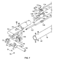
- FIG. 7 is an exploded detail view of the drywall tool mounting plate and brake assembly of the handle of FIG. 1 .
- FIG. 8 is a detail perspective view of the brake grip of the handle of FIG. 1 .
- extendable handle 10 for a drywall tool comprising an outer tube 14 that is slidably coupled to an inner tube 12 , such that the inner tube telescopes within the outer tube.
- inner tube 12 has a D-shaped cross-section with a flat face 16 .
- a series of holes 18 are formed in flat face 16 and disposed along the length of inner tube 12 .
- the D-shape provides inner tube 12 with increased strength and resistance to bending, and prevents the inner tube from inadvertently twisting or rotating within outer tube 14 .
- the plane of flat face 16 is oriented generally parallel to the direction of the bending forces experienced by handle 10 during use, such as the pressure applied to the handle by the user and the weight of the drywall tool.
- the drywall tool is a flat finishing tool that is used to apply mastic to a wall with a vertical motion
- the plane of flat face 16 is oriented perpendicular to the floor.
- the length of handle 10 is changed by telescoping inner tube 12 within outer tube 14 until the appropriate length is achieved and then reversibly locking the inner and outer tubes in place relative to each other to fix the length of the handle.
- inner and outer tubes 12 , 14 are locked together by a lever actuated lock.
- the lever and lock are spaced apart circumferentially on the handle, to reduce the chance that the user's hand or fingers may become caught in the mechanism of the lock or between the lever and a tube when the lever is operated.
- the locking mechanism described herein comprises a locking pin 28 that engages a corresponding opening 18
- inner and outer tubes 12 , 14 may be reversibly locked together by a friction lock or ratcheting mechanism, as are well known in the art.
- a locking assembly 20 is positioned at end 22 of outer tube 14 , that comprises a base 24 , a locking lever 26 , a locking pin 28 and yoke 30 .
- Base 24 encircles outer tube 14 and is attached to end 22 by screws 32 .
- Locking lever 26 has a generally elongated triangular shape with a narrow end 34 connected to base 24 by a pivot 36 , and a wide end 38 that provides a relatively broad surface for the user to manually operate the lever.
- Yoke 30 is connected to locking lever 26 , and extends at least partially around handle 10 .
- yoke 30 is generally U-shaped and extends around base 24 , such that ends 40 a , 40 b of yoke 28 are attached to either side of wide end 38 of locking lever 26 .
- locking lever 26 and locking pin 28 are connected at either end of yoke 30 .
- Locking pin 28 is connected to yoke 30 , and is spaced apart circumferentially from locking lever 26 on handle 10 .
- locking pin 28 is positioned on handle 10 diametrically opposite locking lever 26 .
- the head 42 of locking pin 28 is provided with a groove 44 that is received in a slot 46 formed in the middle portion 48 of yoke 30 .
- locking pin 28 In the locked position, locking pin 28 is engaged in one of holes 18 , which prevents inner tube 12 from sliding relative to outer tube 14 and fixes the length of handle 10 .
- a portion 50 of base 24 extends longitudinally beyond end 22 of outer tube 12 , such that wide end 38 of locking lever 26 , locking pin 28 and yoke 30 overlap inner tube 12 .
- a spring 52 is positioned between base 24 and locking lever 26 to bias wide end 38 of the locking lever away from the base. The action of spring 52 causes wide end 38 to pull yoke 30 and bias locking pin 28 toward inner tube 12 and into engagement with one of holes 18 .
- the user operates locking lever 26 by applying hand pressure to wide end 38 against the spring 52 bias, which causes yoke 30 to withdraw locking pin 28 from the locked position by disengaging the locking pin from hole 18 .
- the user slides inner tube 12 relative to outer tube 14 until the desired length of handle 10 is achieved and locking pin 28 is aligned with the appropriate alternate hole 18 .
- Locking lever 28 is released to allow the bias of spring 52 to cause locking pin 28 to engage an alternate hole 18 and again reversibly lock inner tube 12 and outer tube 14 in position relative to each other.
- base 24 is provided with a slot 54 for receiving yoke 30 .
- Slot 54 is sized and shaped such that yoke 30 is recessed within the slot and does not extend radially beyond the outer surface 56 of base 24 during the operation of locking lever 26 . Because locking assembly 20 does not require any walls to protect the user from the locking mechanism, as in conventional extendable handles, locking assembly is readily accessible for cleaning and repair.
- locking pin 28 is positioned on handle 10 diametrically opposite from locking lever 26 , which further reduces the risk that the user's hand will become caught in the movement of locking pin 28 while operating locking lever 26 .
- the user may maintain his normal grip on handle 10 and apply pressure to locking lever 26 with his palm, which makes locking assembly 20 more comfortable to operate and permits the user to exert more force on the locking lever than conventional extendable handles that are thumb operated.
- a plate 58 is provided for mounting a drywall tool, such as a head for dispensing mastic, to handle 10 .
- plate 58 is adapted to connect to a flat finishing box (not shown), and is pivotally coupled to the end 60 of outer tube 14 by a pin 62 .
- end 60 of outer tube 14 has a U-shaped clamp 64 with sides 66 , 68 .
- An opening 70 sized and shaped to receive pin 62 is formed between sides 66 , 68 at the inside top of the “U.”
- Clamp 64 fits between a pair of spaced apart flanges 72 extending outwardly from plate 58 .
- Flanges 72 have openings 74 that are sized and shaped to receive pin 62 .
- Plate 58 is coupled to clamp 64 by threading pin 62 through openings 74 in the plate and opening 70 in the clamp and then fixing pin 62 to plate 58 with screws 76 .
- Pin 62 rotates freely within opening 70 of clamp 64 , allowing plate 58 and the attached drywall tool to pivot relative to handle 10 .
- a brake assembly is used to control the rotation and fix the angle of plate 58 relative to handle 10 .
- the brake assembly comprises a brake rod 102 , lever 104 and block 106 .
- Brake lever 104 has first and second ends 108 , 110 .
- First end 108 is pivotally connected to brake rod 102 by a pin 111 .
- Second end 110 is inserted through an opening 78 in clamp 64 , and second end 110 has a foot 112 that fits within a notch 80 formed in side 68 of the clamp, as best shown in FIG. 5 .
- Brake block 106 is attached to clamp 64 , and supports second end 110 of lever 104 .
- Retracting rod 102 causes lever 104 to pivot against block 106 such that foot 112 exerts pressure on side 68 of clamp 64 to squeeze side 68 toward side 66 .
- Squeezing sides 66 , 68 of clamp 64 constricts opening 70 and causes the clamp to grip pin 62 and stop plate 58 from rotating relative to handle 10 .
- Brake rod 102 is actuated by squeezing the brake grip 114 positioned at end 82 of inner tube 12 . As shown in FIG. 1 , brake grip 114 and locking lever 26 are positioned 90° apart on the circumference of handle 10 . In a preferred embodiment, brake grip 114 is oriented on handle 10 such that the user does not have to rotate the position of his hand or release his hold on handle 10 to comfortably operate brake grip 114 .
- Grip 114 is coupled to brake rod 102 by a connecting rod 116 that accommodates changes in the length of handle 10 .
- brake rod 102 and connecting rod 116 are held parallel to each other within inner and outer tubes 12 , 14 by housings 118 , 120 positioned at opposite ends 82 , 84 of the inner tube.
- Brake rod 102 is threaded through openings 122 , 124 in housing 120 .
- Connecting rod 116 is threaded through opening 126 in housing 120 , and is seated in slots 128 , 130 in housings 118 , 120 .
- Brake rod 102 and connecting rod 116 are free to slide relative to each other as inner tube 12 telescopes within outer tube 14 .
- Connecting rod 116 has a first end 132 that is coupled to grip 114 ( FIG. 4 ) and a second end 134 that is coupled to brake rod 102 ( FIG. 7 ).
- First end 132 of connecting rod 116 terminates with a threaded link 144 that is pivotally connected to the main shaft 117 of connecting rod 16 by brackets 146 .
- grip 114 is pivotally connected to end 82 of inner tube 12 by a pin 136 .
- Grip 114 includes a pivot 138 that is rotatably mounted in arms 140 that extend toward end 82 .
- Link 144 is received in an opening 142 in pivot 138 .
- An adjustment member such as a nut 148 is mounted on threaded link 144 to retain link 144 in opening 142 and couple link 144 to pivot 138 , such that, when grip 114 is actuated by squeezing, arms 140 rotate away from end 82 of inner tube 12 and pull connecting rod 116 longitudinally toward end 82 .
- connecting rod 116 causes brake rod 102 to retract and stop plate 58 from rotating relative to handle 10 , as described above.
- end 134 of connecting rod 116 is pivotally connected to the base 150 of a washer 152 by brackets 154 .
- Brake rod 102 is threaded through an opening 156 in washer 152 .
- brake rod 102 slides freely within opening 156 of washer 152 .
- a spring 158 causes washer 152 to pivot at the end 134 of the connecting rod such that the edges of opening 156 contact brake rod 102 .
- the friction created by contact between washer 152 and brake rod 102 is sufficient to cause the brake rod to be pulled by the movement of connecting rod 116 , thereby actuating the brake assembly to hold plate 58 .
- the distance between grip 114 and second end 134 of connecting rod 116 is adjustable, to ensure the proper operation of the brake assembly as the various parts of handle 10 loosen or become worn with use.
- Nut 148 may be rotated on threaded link 144 to pull connecting rod 116 longitudinally toward grip 114 ( FIG. 8 ) and reduce the distance between second end 134 of the connecting rod 116 and grip 114 .
- Nut 148 engages pivot 138 to prevent nut 148 from inadvertently rotating on link 144 and changing the distance between second end 134 of the connecting rod 116 and grip 114 during use. As best shown in FIG.
- the inner end 160 of the nut 148 is scalloped to conform to the shape of pivot 138 , such that nut 148 cannot rotate freely on link 144 while the nut it is in contact with the pivot.
- a spring 162 biases nut 148 toward pivot 138 to ensure that end 160 remains in contact with the pivot during normal use.
- the user mounts a drywall tool, such as a flat finishing tool for applying mastic to a wall, to plate 58 on extendable handle 10 .
- the user may then adjust the length of handle 10 to suit the task. For example, it may be useful to fully extend handle 10 to its greatest length to allow the user to reach the top and bottom of a wall in a single motion.
- the length of handle 10 is adjusted by applying hand pressure to locking lever 26 to disengage locking pin 28 from one of holes 18 along the length of inner tube 12 .
- Inner and outer tubes 12 , 14 are then telescoped to the desired length and the user releases pressure on locking lever 26 to allow locking pin 28 to engage the appropriate hole 18 and lock the inner and outer tubes together.
- Locking pin 28 is biased to engage holes 18 by spring 52 .
- plate 58 pivots on pin 62 to allow the tool to pivot at the end 60 of outer tube 14 and maintain contact with the surface of the wall.
- the user may wish to stop the drywall tool from pivoting and fix the angle of plate 58 relative to handle 10 , such as when the flat finishing tool is removed from the wall after applying mastic.
- the user stops the rotation of plate 58 at the end 60 of outer tube 14 by squeezing brake grip 114 .
- Pin 62 pivots within a clamp 64 that is coupled to grip 114 by brake rod 102 and connecting rod 116 .
- Squeezing brake grip 114 pulls connecting rod 116 longitudinally toward end 82 of inner tube 12 and toward grip 114 .
- Connecting rod 116 is coupled to brake 102 and causes the brake rod to retract and squeeze clamp 64 to hold pin 62 and prevent plate 58 from rotating. To compensate for wear or loosening of the parts from repeated use, the distance between second end 134 of connecting rod 116 and grip 114 is adjustable by turning nut 148 on link 144 .
Landscapes
- Engineering & Computer Science (AREA)
- Architecture (AREA)
- Mechanical Engineering (AREA)
- Civil Engineering (AREA)
- Structural Engineering (AREA)
- Cleaning Implements For Floors, Carpets, Furniture, Walls, And The Like (AREA)
- Orthopedics, Nursing, And Contraception (AREA)
Abstract
Description
Claims (23)
Priority Applications (4)
| Application Number | Priority Date | Filing Date | Title |
|---|---|---|---|
| US11/110,107 US7721377B2 (en) | 2005-04-19 | 2005-04-19 | Extendable handle for drywall tools |
| CA002526004A CA2526004A1 (en) | 2005-04-19 | 2005-11-08 | Extendable handle for drywall tools |
| AU2005232287A AU2005232287A1 (en) | 2005-04-19 | 2005-11-10 | Extendable handle for drywall tools |
| GB0525616A GB2425278A (en) | 2005-04-19 | 2005-11-17 | Extendable handle for drywall tools |
Applications Claiming Priority (1)
| Application Number | Priority Date | Filing Date | Title |
|---|---|---|---|
| US11/110,107 US7721377B2 (en) | 2005-04-19 | 2005-04-19 | Extendable handle for drywall tools |
Publications (2)
| Publication Number | Publication Date |
|---|---|
| US20060230564A1 US20060230564A1 (en) | 2006-10-19 |
| US7721377B2 true US7721377B2 (en) | 2010-05-25 |
Family
ID=35736247
Family Applications (1)
| Application Number | Title | Priority Date | Filing Date |
|---|---|---|---|
| US11/110,107 Active 2029-02-23 US7721377B2 (en) | 2005-04-19 | 2005-04-19 | Extendable handle for drywall tools |
Country Status (4)
| Country | Link |
|---|---|
| US (1) | US7721377B2 (en) |
| AU (1) | AU2005232287A1 (en) |
| CA (1) | CA2526004A1 (en) |
| GB (1) | GB2425278A (en) |
Cited By (19)
| Publication number | Priority date | Publication date | Assignee | Title |
|---|---|---|---|---|
| US20090129957A1 (en) * | 2007-11-16 | 2009-05-21 | Cinta Tools Llc | Drywall Mud Pump With Improved Connection Between The Piston And The Rod |
| US20100260879A1 (en) * | 2009-03-20 | 2010-10-14 | Schlecht Werner L | Tool for dispensing drywall joint compound |
| US20110095213A1 (en) * | 2009-10-26 | 2011-04-28 | CINTA Tools Inc. | Hydraulic apparatus, handle, and method of providing an extendable handle |
| US20110189039A1 (en) * | 2010-02-01 | 2011-08-04 | CINTA Tools Inc. | Drywall mud pump with improved handle |
| US20110189038A1 (en) * | 2010-02-01 | 2011-08-04 | CINTA Tools Inc. | Drywall mud pump with clamp or improved foot valve |
| US20110297327A1 (en) * | 2010-06-01 | 2011-12-08 | Axia Acquisition Corporation | Finisher system |
| US8132283B1 (en) * | 2008-10-14 | 2012-03-13 | Downes Timothy P | Cleaning apparatus |
| US20120222269A1 (en) * | 2011-03-03 | 2012-09-06 | Anderson Steven L | Portable assist handle for vehicle entry and exit |
| US8272105B2 (en) | 2009-10-26 | 2012-09-25 | Cinta Tools, Llc | Extendable linkage, extendable handle, and drywall tool with extendable handle |
| US8464391B2 (en) | 2007-04-03 | 2013-06-18 | Diversey, Inc. | Mop head fixation device and method |
| US20140259534A1 (en) * | 2013-03-15 | 2014-09-18 | Rodney M. Shields | Modular telescoping power pole and bar clamp/spreader tool |
| USD719712S1 (en) | 2012-09-07 | 2014-12-16 | Diversey, Inc. | Floor maintenance tool |
| US20160000017A1 (en) * | 2014-07-02 | 2016-01-07 | Todd Pringnitz | Light pole saw |
| US20170079215A1 (en) * | 2014-03-17 | 2017-03-23 | Suzhou Cleva Electric Appliance Co., Ltd. | Extension Rod and Power Tool Having Extension Rod |
| USD864508S1 (en) | 2018-06-06 | 2019-10-22 | Markham Wheeler | Wall angle cleaning tool |
| USD871004S1 (en) | 2018-06-06 | 2019-12-24 | Markham Wheeler | Abrasive cover for a cleaning tool |
| US10945381B1 (en) | 2014-07-02 | 2021-03-16 | Outdoor Product Innovations, Inc. | Modular tools with detachable coupling |
| US20240216944A1 (en) * | 2021-10-07 | 2024-07-04 | Ames Tools Corporation | Compound applicator |
| US12280487B2 (en) * | 2019-08-05 | 2025-04-22 | Ames Tools Corporation | Handle assembly for a finisher box |
Families Citing this family (5)
| Publication number | Priority date | Publication date | Assignee | Title |
|---|---|---|---|---|
| USD563751S1 (en) * | 2006-08-18 | 2008-03-11 | Lanz Donald D | Socket mount, angle adjustable tool holder for extension poles |
| TW201102237A (en) * | 2009-07-03 | 2011-01-16 | Natura Innovation Ltd | Telescopic positioning structure of hand scissors |
| US9133631B2 (en) * | 2010-06-01 | 2015-09-15 | Axia Acquisition Corporation | Handle system for finishing tool |
| US20180347209A1 (en) * | 2017-06-06 | 2018-12-06 | Anirudh Kalbag | Drywall mud applicator handle |
| CN118091200B (en) * | 2023-12-26 | 2024-12-27 | 广东安普宏商电气有限公司 | High-voltage equipment detection device with chuck |
Citations (16)
| Publication number | Priority date | Publication date | Assignee | Title |
|---|---|---|---|---|
| US2934937A (en) | 1958-04-02 | 1960-05-03 | Lucius L Bennett | Adjustable trowel device |
| US3090984A (en) | 1961-03-23 | 1963-05-28 | John M Dunnigan | Implement for overhead tool manipulation |
| US3105262A (en) | 1960-04-26 | 1963-10-01 | Lathrop Castle Euterprises Inc | Tape finishing tools for corners |
| US3146481A (en) | 1962-02-26 | 1964-09-01 | Chiuchiarelli Enzo | Adjustable trowel |
| US4185936A (en) * | 1977-08-05 | 1980-01-29 | Kenlock Corporation | Locking device in a telescopic tripod leg assembly |
| US4592797A (en) | 1985-07-16 | 1986-06-03 | Carl Carlson | Tool for finishing taped dry wall joints |
| US4761092A (en) * | 1984-10-05 | 1988-08-02 | Koma Nakatani | Lock for telescoping tubular leg |
| US5088147A (en) * | 1989-08-08 | 1992-02-18 | Concorde Tool Corp. | Adjustable length handle for flat finishers |
| US5625923A (en) * | 1995-12-28 | 1997-05-06 | Huang; Li-Chu C. | Stroller length-adjustable handle |
| US5791805A (en) | 1994-01-21 | 1998-08-11 | Interlock Industries Limited | Locking device for telescoping elements |
| US6260238B1 (en) * | 1999-10-07 | 2001-07-17 | Macmillan Donald Mark | Adjustable length handle for flat finishers |
| DE10054612A1 (en) | 2000-04-03 | 2001-10-04 | Exel Oy | Connector for telescopic tubes comprises sleeve which fits over both tubes and contains locking components with radial cam surfaces actuated by locking lever mounted on bolt at right angles to length of sleeve |
| US6367121B1 (en) | 2000-06-19 | 2002-04-09 | Macmillan Donald M. | Adjustable length handle for flat finishers |
| US20020081146A1 (en) * | 2000-12-27 | 2002-06-27 | Erwin Tomm | Lever-activated lock for telescoping pole |
| US6412138B1 (en) | 2000-02-11 | 2002-07-02 | Macmillan Donald M. | Adjustable length handle for flat finishers |
| US6551226B1 (en) * | 2000-09-28 | 2003-04-22 | Hoist Fitness Systems | Adjustment apparatus for exercise machine |
-
2005
- 2005-04-19 US US11/110,107 patent/US7721377B2/en active Active
- 2005-11-08 CA CA002526004A patent/CA2526004A1/en not_active Abandoned
- 2005-11-10 AU AU2005232287A patent/AU2005232287A1/en not_active Abandoned
- 2005-11-17 GB GB0525616A patent/GB2425278A/en not_active Withdrawn
Patent Citations (17)
| Publication number | Priority date | Publication date | Assignee | Title |
|---|---|---|---|---|
| US2934937A (en) | 1958-04-02 | 1960-05-03 | Lucius L Bennett | Adjustable trowel device |
| US3105262A (en) | 1960-04-26 | 1963-10-01 | Lathrop Castle Euterprises Inc | Tape finishing tools for corners |
| US3090984A (en) | 1961-03-23 | 1963-05-28 | John M Dunnigan | Implement for overhead tool manipulation |
| US3146481A (en) | 1962-02-26 | 1964-09-01 | Chiuchiarelli Enzo | Adjustable trowel |
| US4185936A (en) * | 1977-08-05 | 1980-01-29 | Kenlock Corporation | Locking device in a telescopic tripod leg assembly |
| US4761092A (en) * | 1984-10-05 | 1988-08-02 | Koma Nakatani | Lock for telescoping tubular leg |
| US4592797A (en) | 1985-07-16 | 1986-06-03 | Carl Carlson | Tool for finishing taped dry wall joints |
| US5088147A (en) * | 1989-08-08 | 1992-02-18 | Concorde Tool Corp. | Adjustable length handle for flat finishers |
| US5791805A (en) | 1994-01-21 | 1998-08-11 | Interlock Industries Limited | Locking device for telescoping elements |
| US5625923A (en) * | 1995-12-28 | 1997-05-06 | Huang; Li-Chu C. | Stroller length-adjustable handle |
| US6260238B1 (en) * | 1999-10-07 | 2001-07-17 | Macmillan Donald Mark | Adjustable length handle for flat finishers |
| US6412138B1 (en) | 2000-02-11 | 2002-07-02 | Macmillan Donald M. | Adjustable length handle for flat finishers |
| DE10054612A1 (en) | 2000-04-03 | 2001-10-04 | Exel Oy | Connector for telescopic tubes comprises sleeve which fits over both tubes and contains locking components with radial cam surfaces actuated by locking lever mounted on bolt at right angles to length of sleeve |
| US6367121B1 (en) | 2000-06-19 | 2002-04-09 | Macmillan Donald M. | Adjustable length handle for flat finishers |
| US6551226B1 (en) * | 2000-09-28 | 2003-04-22 | Hoist Fitness Systems | Adjustment apparatus for exercise machine |
| US20020081146A1 (en) * | 2000-12-27 | 2002-06-27 | Erwin Tomm | Lever-activated lock for telescoping pole |
| WO2002051562A1 (en) | 2000-12-27 | 2002-07-04 | Ervin Tomm | Lever-activated lock for telescoping pole |
Cited By (29)
| Publication number | Priority date | Publication date | Assignee | Title |
|---|---|---|---|---|
| US8959699B2 (en) | 2007-04-03 | 2015-02-24 | Diversey, Inc. | Mop head fixation device and method |
| US8464391B2 (en) | 2007-04-03 | 2013-06-18 | Diversey, Inc. | Mop head fixation device and method |
| US8105058B2 (en) | 2007-11-16 | 2012-01-31 | Cinta Tools Llc | Drywall mud pump with improved connection between the piston and the rod |
| US20090129957A1 (en) * | 2007-11-16 | 2009-05-21 | Cinta Tools Llc | Drywall Mud Pump With Improved Connection Between The Piston And The Rod |
| US8132283B1 (en) * | 2008-10-14 | 2012-03-13 | Downes Timothy P | Cleaning apparatus |
| US20100260879A1 (en) * | 2009-03-20 | 2010-10-14 | Schlecht Werner L | Tool for dispensing drywall joint compound |
| US8272105B2 (en) | 2009-10-26 | 2012-09-25 | Cinta Tools, Llc | Extendable linkage, extendable handle, and drywall tool with extendable handle |
| US8356548B2 (en) | 2009-10-26 | 2013-01-22 | Cinta Tools, Llc | Hydraulic apparatus, handle, and method of providing an extendable handle |
| US20110095213A1 (en) * | 2009-10-26 | 2011-04-28 | CINTA Tools Inc. | Hydraulic apparatus, handle, and method of providing an extendable handle |
| US20110189038A1 (en) * | 2010-02-01 | 2011-08-04 | CINTA Tools Inc. | Drywall mud pump with clamp or improved foot valve |
| US20110189039A1 (en) * | 2010-02-01 | 2011-08-04 | CINTA Tools Inc. | Drywall mud pump with improved handle |
| US20110297327A1 (en) * | 2010-06-01 | 2011-12-08 | Axia Acquisition Corporation | Finisher system |
| US8826961B2 (en) * | 2010-06-01 | 2014-09-09 | Axia Acquisition Corporation | Finisher system |
| US20120222269A1 (en) * | 2011-03-03 | 2012-09-06 | Anderson Steven L | Portable assist handle for vehicle entry and exit |
| USD719712S1 (en) | 2012-09-07 | 2014-12-16 | Diversey, Inc. | Floor maintenance tool |
| US9610678B2 (en) * | 2013-03-15 | 2017-04-04 | Mindflow Llc | Modular telescoping power pole and bar clamp/spreader tool |
| US20140259534A1 (en) * | 2013-03-15 | 2014-09-18 | Rodney M. Shields | Modular telescoping power pole and bar clamp/spreader tool |
| US10849277B2 (en) * | 2014-03-17 | 2020-12-01 | Suzhou Cleva Electric Appliance Co., Ltd. | Extension rod and power tool having extension rod |
| US20170079215A1 (en) * | 2014-03-17 | 2017-03-23 | Suzhou Cleva Electric Appliance Co., Ltd. | Extension Rod and Power Tool Having Extension Rod |
| US20160000017A1 (en) * | 2014-07-02 | 2016-01-07 | Todd Pringnitz | Light pole saw |
| US10091948B2 (en) * | 2014-07-02 | 2018-10-09 | Wicked Tuff Gear, Llc | Light pole saw |
| US10945381B1 (en) | 2014-07-02 | 2021-03-16 | Outdoor Product Innovations, Inc. | Modular tools with detachable coupling |
| USD871004S1 (en) | 2018-06-06 | 2019-12-24 | Markham Wheeler | Abrasive cover for a cleaning tool |
| USD864508S1 (en) | 2018-06-06 | 2019-10-22 | Markham Wheeler | Wall angle cleaning tool |
| US12280487B2 (en) * | 2019-08-05 | 2025-04-22 | Ames Tools Corporation | Handle assembly for a finisher box |
| US20240216944A1 (en) * | 2021-10-07 | 2024-07-04 | Ames Tools Corporation | Compound applicator |
| US20240216945A1 (en) * | 2021-10-07 | 2024-07-04 | Ames Tools Corporation | Compound applicator |
| US12263500B2 (en) * | 2021-10-07 | 2025-04-01 | Ames Tools Corporation | Compound applicator |
| US12263501B2 (en) * | 2021-10-07 | 2025-04-01 | Ames Tools Corporation | Compound applicator |
Also Published As
| Publication number | Publication date |
|---|---|
| GB0525616D0 (en) | 2006-01-25 |
| GB2425278A (en) | 2006-10-25 |
| AU2005232287A1 (en) | 2006-11-02 |
| US20060230564A1 (en) | 2006-10-19 |
| CA2526004A1 (en) | 2006-10-19 |
Similar Documents
| Publication | Publication Date | Title |
|---|---|---|
| US7721377B2 (en) | Extendable handle for drywall tools | |
| US6324947B2 (en) | Locking swivel wrench | |
| US5088147A (en) | Adjustable length handle for flat finishers | |
| US4483562A (en) | Locking flexible shaft device with live distal end attachment | |
| CN101568408B (en) | Pliers with hinged pin that can move against spring force | |
| US6367121B1 (en) | Adjustable length handle for flat finishers | |
| US5099539A (en) | Telescoping extension rod having pivotably adjustable tool head | |
| CA2181683C (en) | A locking device for telescoping elements | |
| US8032990B2 (en) | Handles for hand-held tools | |
| US20150314425A1 (en) | Ratchet wrench with handgrip ratchet control | |
| US7658390B2 (en) | Extendable wheel barrow handle adapters | |
| US8122569B2 (en) | Auxiliary handle for hand-held power tool | |
| CN101018953A (en) | Two-axis swivel joint | |
| US8444020B1 (en) | Assembly for hand held or remote elevated operation of aerosol spray cans | |
| CA2361472C (en) | Quick adjustment mechanism for blade pitch of concrete power trowel | |
| TWI593520B (en) | Adjustable locking pliers | |
| US20050061449A1 (en) | Ergonomic and easily serviceable taper tool | |
| US20250196181A1 (en) | Compound applicator | |
| CA2031952C (en) | Adjustable length handle for flat finishers | |
| CA2376578C (en) | Adjustable length handle for flat finishers | |
| JP4724819B2 (en) | Power working machine | |
| JP3066567B2 (en) | Remote control device with neck bending mechanism | |
| TWI691265B (en) | Manually operated cutting device | |
| US20070119062A1 (en) | Crown molding tool | |
| GB2259041A (en) | Hammer with pivotable head |
Legal Events
| Date | Code | Title | Description |
|---|---|---|---|
| AS | Assignment |
Owner name: AXIA, INC.,TEXAS Free format text: ASSIGNMENT OF ASSIGNORS INTEREST;ASSIGNORS:JUNGKLAUS, MATT;CASTAGNETTA, DAVID J., JR.;REEL/FRAME:016495/0596 Effective date: 20050418 Owner name: AXIA, INC., TEXAS Free format text: ASSIGNMENT OF ASSIGNORS INTEREST;ASSIGNORS:JUNGKLAUS, MATT;CASTAGNETTA, DAVID J., JR.;REEL/FRAME:016495/0596 Effective date: 20050418 |
|
| AS | Assignment |
Owner name: UBS AG, STAMFORD BRANCH, AS COLLATERAL AGENT,CONNE Free format text: SECURITY AGREEMENT;ASSIGNOR:AXIA INCORPORATED;REEL/FRAME:016945/0748 Effective date: 20051221 Owner name: UBS AG, STAMFORD BRANCH, AS COLLATERAL AGENT, CONN Free format text: SECURITY AGREEMENT;ASSIGNOR:AXIA INCORPORATED;REEL/FRAME:016945/0748 Effective date: 20051221 |
|
| AS | Assignment |
Owner name: UBS AG, STAMFORD BRANCH, AS SUBORDINATED COLLATERA Free format text: SUBORDINATED PATENT SECURITY AGREEMENT;ASSIGNOR:AXIA INCORPORATED;REEL/FRAME:021029/0244 Effective date: 20080522 |
|
| AS | Assignment |
Owner name: AXIA ACQUISITION CORPORATION,GEORGIA Free format text: ASSIGNMENT OF ASSIGNORS INTEREST;ASSIGNORS:AXIA INCORPORATED;AMES TAPING TOOL SYSTEMS, INC.;TAPETECH TOOL CO., INC.;AND OTHERS;REEL/FRAME:024066/0984 Effective date: 20100312 Owner name: AXIA ACQUISITION CORPORATION, GEORGIA Free format text: ASSIGNMENT OF ASSIGNORS INTEREST;ASSIGNORS:AXIA INCORPORATED;AMES TAPING TOOL SYSTEMS, INC.;TAPETECH TOOL CO., INC.;AND OTHERS;REEL/FRAME:024066/0984 Effective date: 20100312 |
|
| AS | Assignment |
Owner name: AXIA INCORPORATED,CALIFORNIA Free format text: RELEASE OF SECURITY INTEREST IN PATENTS;ASSIGNOR:UBS AG, STAMFORD BRANCH, AS SENIOR COLLATERAL AGENT;REEL/FRAME:024079/0646 Effective date: 20100312 Owner name: AXIA INCORPORATED,CALIFORNIA Free format text: RELEASE OF SECURITY INTEREST IN PATENTS;ASSIGNOR:UBS AG, STAMFORD BRANCH, AS SUBORDINATED COLLATERAL AGENT;REEL/FRAME:024079/0662 Effective date: 20100312 Owner name: BROADPOINT PRODUCTS CORP.,NEW YORK Free format text: FIRST LIEN PATENT SECURITY AGREEMENT;ASSIGNOR:AXIA ACQUISITION CORPORATION;REEL/FRAME:024079/0704 Effective date: 20100312 Owner name: BROADPOINT PRODUCTS CORP., AS ADMINISTRATIVE AGENT Free format text: SECOND LIEN PATENT SECURITY AGREEMENT;ASSIGNOR:AXIA ACQUISITION CORPORATION;REEL/FRAME:024079/0720 Effective date: 20100312 Owner name: AXIA INCORPORATED, CALIFORNIA Free format text: RELEASE OF SECURITY INTEREST IN PATENTS;ASSIGNOR:UBS AG, STAMFORD BRANCH, AS SENIOR COLLATERAL AGENT;REEL/FRAME:024079/0646 Effective date: 20100312 Owner name: AXIA INCORPORATED, CALIFORNIA Free format text: RELEASE OF SECURITY INTEREST IN PATENTS;ASSIGNOR:UBS AG, STAMFORD BRANCH, AS SUBORDINATED COLLATERAL AGENT;REEL/FRAME:024079/0662 Effective date: 20100312 Owner name: BROADPOINT PRODUCTS CORP., NEW YORK Free format text: FIRST LIEN PATENT SECURITY AGREEMENT;ASSIGNOR:AXIA ACQUISITION CORPORATION;REEL/FRAME:024079/0704 Effective date: 20100312 |
|
| STCF | Information on status: patent grant |
Free format text: PATENTED CASE |
|
| FPAY | Fee payment |
Year of fee payment: 4 |
|
| FEPP | Fee payment procedure |
Free format text: PAT HOLDER CLAIMS SMALL ENTITY STATUS, ENTITY STATUS SET TO SMALL (ORIGINAL EVENT CODE: LTOS); ENTITY STATUS OF PATENT OWNER: SMALL ENTITY |
|
| AS | Assignment |
Owner name: AXIA ACQUISITION CORPORATION, CALIFORNIA Free format text: RELEASE OF SECURITY INTEREST IN PATENTS;ASSIGNOR:CORTLAND PRODUCTS CORP. F/K/A BROADPOINT PRODUCTS CORP., AS ADMINISTRATIVE AGENT;REEL/FRAME:031806/0001 Effective date: 20131212 |
|
| AS | Assignment |
Owner name: AXIA ACQUISITION CORPORATION, CALIFORNIA Free format text: RELEASE OF SECURITY INTEREST IN PATENTS;ASSIGNOR:CORTLAND PRODUCTS CORP. F/K/A BROADPOINT PRODUCTS CORP., AS ADMINISTRATIVE AGENT;REEL/FRAME:033283/0193 Effective date: 20140708 |
|
| AS | Assignment |
Owner name: WELLS FARGO BANK, NATIONAL ASSOCIATION, GEORGIA Free format text: ASSIGNMENT OF ASSIGNORS INTEREST;ASSIGNOR:AXIA ACQUISITION CORPORATION;REEL/FRAME:041202/0976 Effective date: 20170202 |
|
| AS | Assignment |
Owner name: LBC CREDIT AGENCY SERVICES, LLC, PENNSYLVANIA Free format text: SECURITY INTEREST;ASSIGNOR:AXIA ACQUISITION CORPORATION;REEL/FRAME:043636/0580 Effective date: 20170915 |
|
| AS | Assignment |
Owner name: AXIA ACQUISITION HOLDING CORPORATION, GEORGIA Free format text: RELEASE;ASSIGNOR:WELLS FARGO BANK, NATIONAL ASSOCIATION;REEL/FRAME:044968/0761 Effective date: 20171010 |
|
| MAFP | Maintenance fee payment |
Free format text: PAYMENT OF MAINTENANCE FEE, 8TH YR, SMALL ENTITY (ORIGINAL EVENT CODE: M2552) Year of fee payment: 8 |
|
| AS | Assignment |
Owner name: WELLS FARGO BANK, NATIONAL ASSOCIATION, GEORGIA Free format text: CORRECTIVE ASSIGNMENT TO CORRECT THE THE NATURE OF CONVEYANCE SECURITY INTEREST PREVIOUSLY RECORDED AT REEL: 041202 FRAME: 0976. ASSIGNOR(S) HEREBY CONFIRMS THE ASSIGNMENT;ASSIGNOR:AXIA ACQUISITION CORPORATION;REEL/FRAME:057859/0357 Effective date: 20170202 |
|
| MAFP | Maintenance fee payment |
Free format text: PAYMENT OF MAINTENANCE FEE, 12TH YR, SMALL ENTITY (ORIGINAL EVENT CODE: M2553); ENTITY STATUS OF PATENT OWNER: SMALL ENTITY Year of fee payment: 12 |
|
| AS | Assignment |
Owner name: WELLS FARGO BANK, N.A., GEORGIA Free format text: SECURITY INTEREST;ASSIGNOR:AMES TOOLS CORPORATION;REEL/FRAME:058778/0513 Effective date: 20220114 |
|
| AS | Assignment |
Owner name: AXIA ACQUISITION CORPORATION, GEORGIA Free format text: RELEASE BY SECURED PARTY;ASSIGNOR:LBC CREDIT AGENCY SERVICES, LLC;REEL/FRAME:063606/0181 Effective date: 20211130 |
|
| AS | Assignment |
Owner name: JPMORGAN CHASE BANK, N.A., AS COLLATERAL AGENT, ILLINOIS Free format text: INTELLECTUAL PROPERTY SECURITY AGREEMENT SUPPLEMENT;ASSIGNOR:AMES TOOLS CORPORATION (F/K/A AXIA ACQUISITION CORPORATION);REEL/FRAME:063633/0308 Effective date: 20230512 |
|
| AS | Assignment |
Owner name: AMES TOOLS CORPORATION, GEORGIA Free format text: MERGER AND CHANGE OF NAME;ASSIGNORS:AXIA ACQUISITION CORPORATION;AMES TAPING TOOLS HOLDING LLC;AXIA ACQUISITION HOLDING CORPORATION;REEL/FRAME:063767/0842 Effective date: 20211201 Owner name: AMES TOOLS CORPORATION, GEORGIA Free format text: MERGER AND CHANGE OF NAME;ASSIGNORS:AXIA ACQUISITION CORPORATION;AMES TAPING TOOLS HOLDING LLC;AXIA ACQUISITION HOLDING CORPORATION;AND OTHERS;REEL/FRAME:063767/0842 Effective date: 20211201 |
|
| AS | Assignment |
Owner name: AMES TOOLS CORPORATION, GEORGIA Free format text: RELEASE OF INTELLECTUAL PROPERTY SECURITY AGREEMENT RECORDED AT RF 063633/0308;ASSIGNOR:JPMORGAN CHASE BANK, N.A. (AS SUCCESSOR TO CREDIT SUISSE AG) AS COLLATERAL AGENT;REEL/FRAME:072804/0308 Effective date: 20250904 |
|
| AS | Assignment |
Owner name: AMES TOOLS CORPORATION, GEORGIA Free format text: TERMINATION AND RELEASE OF SECURITY INTEREST IN PATENTS AND TRADEMARKS;ASSIGNOR:WELLS FARGO BANK, NATIONAL ASSOCIATION;REEL/FRAME:072812/0877 Effective date: 20250904 |