US7720480B2 - System and method for reducing a no-communication period during hand-off - Google Patents
System and method for reducing a no-communication period during hand-off Download PDFInfo
- Publication number
- US7720480B2 US7720480B2 US11/633,418 US63341806A US7720480B2 US 7720480 B2 US7720480 B2 US 7720480B2 US 63341806 A US63341806 A US 63341806A US 7720480 B2 US7720480 B2 US 7720480B2
- Authority
- US
- United States
- Prior art keywords
- data
- communication
- communication connection
- connection apparatus
- section
- Prior art date
- Legal status (The legal status is an assumption and is not a legal conclusion. Google has not performed a legal analysis and makes no representation as to the accuracy of the status listed.)
- Expired - Fee Related, expires
Links
- 238000004891 communication Methods 0.000 title claims abstract description 703
- 238000000034 method Methods 0.000 title claims description 29
- 238000012545 processing Methods 0.000 claims abstract description 146
- 230000005540 biological transmission Effects 0.000 claims description 132
- 239000000284 extract Substances 0.000 claims description 33
- 230000001939 inductive effect Effects 0.000 claims 1
- 238000010586 diagram Methods 0.000 description 52
- 230000008859 change Effects 0.000 description 30
- 230000006870 function Effects 0.000 description 29
- 238000012546 transfer Methods 0.000 description 14
- 230000000694 effects Effects 0.000 description 6
- 230000015654 memory Effects 0.000 description 5
- 238000012544 monitoring process Methods 0.000 description 3
- 230000008569 process Effects 0.000 description 3
- 230000008901 benefit Effects 0.000 description 2
- 238000006243 chemical reaction Methods 0.000 description 2
- 238000007796 conventional method Methods 0.000 description 2
- 230000002093 peripheral effect Effects 0.000 description 2
- 230000009467 reduction Effects 0.000 description 2
- 230000004044 response Effects 0.000 description 2
- 238000000926 separation method Methods 0.000 description 2
- 238000012790 confirmation Methods 0.000 description 1
- 238000001514 detection method Methods 0.000 description 1
- 230000007246 mechanism Effects 0.000 description 1
- 238000010295 mobile communication Methods 0.000 description 1
- 230000008054 signal transmission Effects 0.000 description 1
Images


Classifications
-
- H—ELECTRICITY
- H04—ELECTRIC COMMUNICATION TECHNIQUE
- H04W—WIRELESS COMMUNICATION NETWORKS
- H04W36/00—Hand-off or reselection arrangements
- H04W36/02—Buffering or recovering information during reselection ; Modification of the traffic flow during hand-off
Definitions
- the present invention relates to a communication method and a communication system, and, more particularly to a communication method and a communication system used for a radio communication system that uses Data Rate Control (DRC) and Data Source Control (DSC).
- DRC Data Rate Control
- DSC Data Source Control
- a system for such data communication using mobile terminals includes, for example, a communication terminal apparatus (Access Terminal, hereinafter referred to as AT) serving as a mobile terminal, a communication connection apparatus (Base Station, hereinafter referred to as BS) serving as a fixed station, a communication control apparatus (Base Station Control, hereinafter referred to as BSC) that connects plural communication connection apparatuses, and an external network such as a public network.
- AT Access Terminal
- BS communication connection apparatus
- BSC Base Station Control
- the BSC transfers the data to the BS.
- the BS transfers data to the AT according to radio communication.
- it has become a general practice to follow the standardized data transmission procedure described in 3GPP2C.S0024 (Non-patent Document 1).
- Handoff When the AT moves, the AT is required to switch a communication destination from a certain BS to another BS and continue the data communication.
- This switching operation is referred to as Handoff.
- As a basic operation of the Handoff for example, there are operations such as securing of a radio communication path with a moving destination BS, switching of a data reception source BS, and opening of a radio communication path with a moving source BS.
- the AT requests the BS and the BSC to secure and open the radio communication path.
- the AT has a function of selecting a BS with a best reception state on the basis of reception intensity of a radio wave and notifying a result of the selection to the BS and the BSC as a Data Rate Control (DRC) signal.
- the BSC has a function of determining a BS at a transfer destination of data on the basis of a DRC received from the AT.
- the BS has a function of transmitting the data to the AT only when the BS receives a DRC, which is transferred to the BS, from the AT.
- the DRC signal includes a DRC Cover value.
- the DRC Cover value is determined for each BS.
- the AT notifies the BS of a DRC Cover value of a BS selected as a communication destination by carrying the DRC Cover value on a DRC signal.
- the BSC When data is lost while the data is transferred from the BSC to the AT, in order to transmit the data again to compensate for the loss, the BSC has a function of accumulating data for retransmission, a function of granting continuous sequence numbers to the respective data at the time of data transmission, and a function of retransmitting the data in response to a retransmission request from the AT.
- the AT has a function of checking the sequence numbers granted to the data to detect loss of the data and a function of transmitting a message for requesting retransmission of the lost data (a Nak message) to the BSC.
- Non-patent Document 2 a system for notifying a BS and a BSC of a BS at a Handoff destination from an AT using a DSC (Data Source Control) signal a fixed time before the AT issues an instruction for switching DRC is described.
- the AT has a function of notifying the BS and the BSC of the DSC switching instruction before switching the DRC.
- the BSC has a function of not only transmitting data to a BS indicated by a DRC but also transmitting data to a BS indicated by a DSC. Since the BSC receives the notice of the DSC in this way, the BSC can predict DRC switching in advance.
- Non-patent Document 2 By transmitting identical data to plural BSs from the BSC, the data is transmitted to the AT from the BS without spending time at the time of the DRC switching. This makes it possible to eliminate a no-communication period at the time of DRC switching, which is a problem in the Non-patent Document 1.
- These methods of transmitting data using the DSC are explained in detail in, for example, Chapter 11.7.6.1.5 and Chapter 14.2.1.3.3.3 of C.S0024-A (Non-patent Document 2).
- a receiver when a receiver detects loss of segments, the receiver transmits a minimum sequence number of the lost segments and a confirmation response including a value indicating the number of the lost segments as an advertised window size to a transmitter (see, for example, Patent Document 1).
- the Non-patent Document 2 As described above, as a technique for reducing a no-communication period, the Non-patent Document 2 is disclosed.
- a BS for which Handoff is predicted to be performed by the DSC is notified to the BSC in advance and data is transmitted from the BSC to both a BS at a Handoff source and the BS predicted as a Handoff destination to reduce a no-communication period that appears between the AT and the BS.
- the BS at the Hand off destination cannot learn to which extent the BS at the Handoff source has sent the data to the AT and to which extent the AT has received the data.
- the BS at the Handoff destination transmits data accumulated by the BS itself to the AT regardless of to which extent the AT has received the data from the BS at the Handoff source.
- the AT cannot receive continuous data unless a sequence number of data that the AT received last from the BS at the Handoff source and a sequence number of data from which the BS at the Handoff destination started transmission to the AT are continuous.
- a sequence number (e.g., 50) of data that the AT received last from the BS at the Handoff source is larger than a sequence number (e.g., 30) of data from which the BS at the Handoff destination started transmission to the AT, since identical data (e.g., 30 to 50) passes a radio section, efficiency of use of the radio section falls.
- a sequence number (e.g., 70) of data from which the BS at the Handoff destination started transmission to the AT is smaller than a sequence number (e.g. 50) of data that the AT received last from the BS at the Handoff source, data from which data (S51 to 69) is lost arrives at the AT from the BS.
- the AT since the AT has to notify a Nak message to the BSC through the BS and retransmit the data to the AT from the BSC through the BS, a delay equivalent to the retransmission occurs.
- a sequence number of lost data is notified from the AT to the BSC to specify data that should be retransmitted.
- a sequence number of data that the AT received last from a BS at a switching source is notified to a switching destination BS using this Nak message.
- transmission of retransmission data originally carried out by the BSC is performed by the BS.
- the BS provided in the communication system accumulates data transmitted from the BSC in the BS.
- a DSC instruction from the AT designates the own BS
- data received last from the BSC is transmitted to the AT out of the data accumulated in the BS.
- retransmission processing of data by the Nak message performed by the BSC is performed by the BS.
- the BS includes a data accumulating section that accumulates data transmitted from the BSC in the BS, a Nak message analyzing section that analyzes a Nak message notified from the AT and extracts a sequence number, and a data retransmitting section that retransmits the data from the BS to the AT in accordance with the sequence number extracted by the Nak message analyzing section.
- the BS also includes a DRC judging section that receives a DRC signal from the AT and judges whether the DRC signal is a DRC instruction to the own BS and a DSC judging section that receives a DSC signal from the AT and judges whether the DSC signal is a DSC instruction to the own BS.
- the BS includes a data transmitting section that judges, on the basis of results of the DRC judging section and the DSC judging section, timing at which the DRC is switched to another BS to the own BS in a state in which the DSC faces the own BS, extracts latest data from the data accumulating section, and transmits the latest data.
- the AT transmits DRC indicating switching from the BS at the Handoff source to the BS at the Handoff destination and the BS at the Handoff destination receives the DRC
- the BS at the Handoff destination transmits latest data among the accumulated data to the AT.
- the AT transmits a Nak message in order to request the BS to retransmit data lost between data received last from the BS at the Handoff source and the data received from the BS at the Handoff destination.
- the BS at the Handoff destination which has received the Nak message, extracts the data missing in the AT from the data accumulating section in accordance with the Nak message and transmits the data to the AT.
- a communication terminal apparatus connected to a communication network using radio includes, for example:
- a data receiving section that receives data from the communication network
- a data loss processing section that detects loss of the data received by the data receiving section and creates a request for retransmission to the communication network
- a data transmitting section that transmits the request for retransmission created by the data loss processing section to the communication network.
- the data loss processing section includes, for example, a sequence number judging section and a NAK message creating section.
- a communication terminal apparatus of another form connected to a communication network using radio includes, for example:
- a DRC creating section that selects one data reception source from plural communication networks and creates a DRC (Data Rate Control) signal for a data transmission request;
- a DSC creating section that creates a DSC (Data Source Control) signal for a notice of switching a fixed time before switching the communication network at the data reception source in the DRC creating section;
- a data transmitting section that transmits the signals generated by the DRC creating section and the DSC creating section to the communication network.
- a communication connection apparatus that connects a communication terminal apparatus to a communication network using radio includes, as one of characteristics, for example:
- a data receiving section that receives data from the communication terminal apparatus
- a DRC judging section that receives the data from the data receiving section and extracts a DRC signal
- a DSC judging section that receives the data from the data receiving section and extracts a DSC signal
- a DSC/DRC transferring section that transmits results of the DRC judging section and the DSC judging section to the communication network
- a data accumulating section that accumulates data received from the communication network
- a data transmission processing section that extracts data from the data accumulating section on the basis of the results of the DRC judging section and the DSC judging section;
- a NAK message analyzing section that receives the data from the data receiving section and extracts a NAK message for a retransmission request
- a data retransmission processing section that extracts data from the data accumulating section on the basis of a result of the NAK message analyzing section
- a data transmitting section that transmits the data of the data transmission processing section and the data retransmission processing section to the communication terminal apparatus.
- a communication control apparatus that connects a communication connection apparatus to a communication network includes, as one of characteristics, for example:
- a data receiving section that receives data from the communication connection apparatus
- a DRC judging section that receives the data from the data receiving section and extracts a DRC signal
- a DSC judging section that receives the data from the data receiving section and extracts a DSC signal
- a data accumulating section that accumulates data received from the communication network
- a data transmission processing section that extracts data from the data accumulating section on the basis of results of the DRC judging section and the DSC judging section;
- a NAK message analyzing section that receives the data from the data receiving section and extracts a NAK message for a retransmission request
- a data retransmission processing section that extracts data from the data accumulating section on the basis of a result of the NAK message analyzing section
- a data transmitting section that transmits the data of the data transmission processing section and the data retransmission processing section to the communication connection apparatus.
- a method of performing communication between a communication terminal apparatus and plural communication connection apparatuses connected using radio including, as one of characteristics:
- latest data in the data accumulating section is transmitted to the communication terminal apparatus when a DRC signal transmitted by the communication terminal apparatus changes from designation of the first communication connection apparatus to designation of the second communication connection apparatus, and
- a data retransmission processing section of the communication connection apparatus transmits data not received by the communication terminal apparatus in accordance with the NAK message.
- a communication method that uses a communication system including first and second communication connection apparatuses that communicate with a communication terminal by radio and a communication control apparatus that connects the first and the second communication connection apparatuses and a predetermined network, the communication method comprising:
- a first data transmission step in which the first communication connection apparatus receives a DRC signal including an identifier of the first communication connection apparatus from the communication terminal and transmits communication data from the communication control apparatus to the communication terminal in accordance with the DRC signal;
- the first communication connection apparatus receives the DRC signal including the identifier of the first communication connection apparatus and a DSC signal including an identifier of the second communication connection apparatus, which are transmitted due to select the second communication connection apparatus by the communication terminal as a switching destination of a communication destination, and transmits a sequence number of data following the communication data transmitted in the first data transmission step and the received DRC signal and the received DSC signal to the communication control apparatus;
- a second data transmission step in which the first communication connection apparatus transmits communication data from the communication control apparatus to the communication terminal in accordance with the DRC signal;
- the communication control apparatus transmits communication data of the sequence number received from the first communication connection apparatus and communication data of subsequent sequence numbers to the second communication connection apparatus in accordance with the DSC signal;
- a accumulating step in which the second communication connection apparatus accumulates the communication data of the sequence number and the subsequent sequence numbers from the communication control apparatus;
- a third data transmission step in which the second communication connection apparatus receives the DRC signal and the DSC signal including the identifier of the second communication connection apparatus from the communication terminal and transmits latest data or predetermined numbered data from the latest data among the communication data accumulated in the accumulating step;
- the second communication connection apparatus receives, from the communication terminal, a retransmission request message for requesting lost data between the communication data received by the communication terminal in the first and the second data transmission step and the data received in the third data transmission step, the retransmission request message including a leading sequence number of the lost data;
- a fourth data transmission step in which the second communication connection apparatus reads out communication data of the leading sequence number included in the received retransmission request message and subsequent sequence numbers among the communication data accumulated in the accumulating step and transmits the communication data to the communication terminal.
- a communication system comprising:
- a first communication connection apparatus that communicates with a communication terminal by radio
- a communication control apparatus that connects the first and the second communication connection apparatuses and a predetermined network
- the first communication connection apparatus receives a DRC signal including an identifier of the first communication connection apparatus from the communication terminal and transmits communication data from the communication control apparatus to the communication terminal in accordance with the DRC signal;
- the first communication connection apparatus receives the DRC signal including the identifier of the first communication connection apparatus and a DSC signal including an identifier of the second communication connection apparatus, which are transmitted due to select the second communication connection apparatus by the communication terminal as a switching destination of a communication destination, and transmits a sequence number of data following the communication data transmitted to the communication terminal and the received DRC signal and the received DSC signal to the communication control apparatus;
- the first communication connection apparatus transmits the communication data from the communication control apparatus to the communication terminal in accordance with the DRC signal;
- the communication control apparatus transmits communication data of the sequence number received from the first communication connection apparatus and communication data of subsequent sequence numbers to the second communication connection apparatus in accordance with the DSC signal;
- the second communication connection apparatus accumulates the communication data of the sequence number and the subsequent sequence numbers from the communication control apparatus;
- the second communication connection apparatus receives the DRC signal and the DSC signal including the identifier of the second communication connection apparatus from the communication terminal and transmits latest data or predetermined numbered data from the latest data among the communication data accumulated;
- the second communication connection apparatus receives, from the communication terminal, a retransmission request message for requesting lost data between the communication data received by the communication terminal from the first communication connection apparatus and the latest data or the predetermined numbered data from the latest data, the retransmission request message including a leading sequence number of the lost data;
- the second communication connection apparatus reads out communication data of the leading sequence number included in the received retransmission request message and subsequent sequence numbers among the communication data accumulated and transmits the communication data to the communication terminal.
- this invention it is possible to provide a communication method and a communication system that can prevent redundant transmission of data in a radio section and a delay of data arrival due to retransmission while inheriting the effect of reduction in a no-communication period.
- this invention it is possible to shift a function of retransmitting data using the Nak message from the BSC to the BS and reduce time until the AT receives retransmission data from the Nak message transmission compared with the conventional system of retransmitting data from the BSC. According to this invention, it is possible to, such that there is no shortage in the data accumulated in the Handoff destination BS at the time of DRC switching, transmit missing data from the BSC to the Handoff destination BS with DSC switching as an opportunity to make it easy to realize the effects of the invention even in a situation in which a switching time is short.
- the retransmission function by the Nak message is a function already provided in the AT and the invention does not need to add a new function to a large number of ATs compared with the BS and the BSC and spread the ATs, make it possible to quickly expand the invention to the market.
- FIG. 1 is a network diagram showing an example of a structure of a communication system that uses a communication terminal apparatus, a communication connection apparatus, and a communication control apparatus;
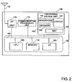
- FIG. 2 is a functional diagram showing an example of a hardware function configuration of the communication terminal apparatus
- FIG. 3 is a functional diagram showing an example of a software function configuration of the communication terminal apparatus
- FIG. 4 is a functional diagram showing an example of a hardware function configuration of the communication connection apparatus (BS: Base Station);
- FIG. 5 is a functional diagram showing an example of a software function configuration of the communication connection apparatus (BS: Base station);
- FIG. 6 is a functional diagram showing an example of a hardware function configuration of the communication control apparatus (BSC: Base Station controller);
- FIG. 7 is a functional diagram showing an example of a hardware function configuration of the communication control apparatus (BSC: Base Station Controller);
- FIG. 8 is a frame diagram showing an example of a structure of data transmitted and received among the communication terminal apparatus, the communication connection apparatus, and the communication control apparatus;
- FIG. 9 is a frame diagram showing examples of structures of a Nak message and a DRC/DSC message transmitted and received among the communication terminal apparatus, the communication connection apparatus, and the communication control apparatus;
- FIG. 10 is an operation flow diagram ( 1 ) showing an example of operations of the communication terminal apparatus
- FIG. 11 is an operation flow diagram ( 2 ) showing an example of operations of the communication terminal apparatus
- FIG. 12 is an operation flow diagram ( 3 ) showing an example of operations of the communication terminal apparatus
- FIG. 13 is an operation flow diagram ( 1 ) showing an example of operations of the communication connection apparatus
- FIG. 14 is an operation flow diagram ( 2 ) showing an example of operations of the communication connection apparatus
- FIG. 15 is an operation flow diagram ( 3 ) showing an example of operations of the communication connection apparatus
- FIG. 16 is an operation flow diagram ( 4 ) showing an example of operations of the communication connection apparatus
- FIG. 17 is an operation flow diagram ( 5 ) showing an example of operations of the communication connection apparatus
- FIG. 18 is an operation flow diagram ( 1 ) showing an example of operations of the communication control apparatus
- FIG. 19 is an operation flow diagram ( 2 ) showing an example of operations of the communication control apparatus
- FIG. 20 is an operation flow diagram ( 3 ) showing an example of operations of the communication control apparatus
- FIG. 21 is an operation flow diagram ( 4 ) showing an example of operations of the communication control apparatus
- FIG. 22 is an operation flow diagram ( 5 ) showing an example of operations of the communication control apparatus
- FIG. 23 is an operation sequence chart ( 1 ) for explaining an example of operations of the communication system
- FIG. 24 is an operation sequence chart ( 2 ) for explaining an example of operations of the communication system
- FIG. 25 is a diagram showing an example of communication switching by a DRC signal
- FIG. 26 is a diagram ( 1 ) showing an example of communication switching by a DRC signal and a DSC signal;
- FIG. 27 is a diagram ( 2 ) showing an example of communication switching by a DRC signal and a DSC signal.
- a communication terminal apparatus, a communication connection apparatus, and a communication control apparatus as well as a communication system and a communication method that use these apparatuses according to an embodiment of the invention will be hereinafter explained in detail using the drawings.
- FIG. 1 is a network diagram showing an example of a structure of the communication system that uses the communication terminal apparatus, the communication connection apparatus, and the communication control apparatus according to this embodiment.
- the communication system includes a radio terminal 100 serving as a communication terminal apparatus, Base Stations (BSs) 200 serving as communication connection apparatuses that connect the radio terminal 100 and a radio link, a Base Station controller (BSC) 300 serving as a communication control apparatus that connects the plural BSs 200 and an IP network 400 such as the Internet, and an Internet Service Provider (ISP) 500 that exchanges application data through the IP network 400 .
- the ISP 500 has, for example, a server 510 that accumulates data.
- the BSs 200 are fixed stations and cannot move. As indicated by areas 10 , a range in which the BSs 200 can communicate with the radio terminal 100 with the radio link is limited. In order to cover an area of a wide range, the plural BSs 200 are set.
- the radio link is switched to a certain BS 200 - 1 (a first communication connection apparatus) to another BS 200 - 2 (a second communication connection apparatus) to maintain the connection of the radio terminal 100 and the ISP 500 .
- a radio terminal 100 - 1 in an area 10 - 1 communicates with the BS 200 - 1 first.
- the radio terminal 100 When the radio terminal 100 moves from (a) to (b) in the figure, the radio terminal 100 communicates with both the BS 200 - 1 and the BS 200 - 2 .
- a radio terminal 100 - 2 which has moved from (b) to (c) in the figure, finally communicates with the BS 200 - 2 .
- the communication system shown in FIG. 1 will be explained as an example.
- FIGS. 2 and 3 are block diagrams showing an example of a structure of the communication terminal apparatus 100 .
- FIG. 2 is a block diagram showing a hardware configuration of the communication terminal apparatus 100 .
- the communication terminal apparatus 100 includes, for example, an antenna 110 that transmits and receives a radio signal; an RF (Radio Frequency) unit 120 that converts the radio signal into an electric signal, a communication processing unit 130 that applies predetermined communication processing (signal termination, protocol conversion, failure monitoring, etc.) to the electric signal, a peripheral device unit 140 that performs input and output of signals transmitted and received by an owner of the terminal, and a control unit 150 that performs control of the entire communication terminal apparatus 100 .
- RF Radio Frequency
- the peripheral device unit 140 has, for example, a microphone 141 for inputting sound, a speaker 142 that outputs sound, a display 143 that displays characters and images, and a key 144 for performing data input and control signal input (designation of a connection destination, etc.).
- the control unit 150 has a CPU 160 serving as a processor that controls operations of the entire communication terminal apparatus 100 , a memory 170 that accumulates operation programs and various data necessary for operations, and an I/O 180 that transmits and receives signals to and from external apparatuses.
- a control line 190 connects the respective blocks described above.
- FIG. 3 is a functional block diagram showing an example of a software configuration of the communication terminal apparatus 100 .
- the communication terminal apparatus 100 includes a radio processing section 1502 that performs radio communication with the BSs 200 , a radio session section 1510 that performs communication of a radio session with the BSs 200 and the BSC 300 , and an application processing section 1501 that processes an application using data received.
- the radio session section 1510 further includes a data receiving section 1511 that receives frame data from the radio processing section 1502 , a sequence number judging section 1512 that extracts a sequence number from the frame data received and judges loss of data, a Nak message creating section 1513 that creates a Nak message (a retransmission request) for data retransmission to be sent to the BSs 200 and the BSC 300 on the basis of a result of the sequence number judging section 1512 , a DRC creating section 1514 that determines an optimum communication destination according to a reception state of a radio wave out of the plural BS 200 and creates a DRC signal for notification to the communication destination, a DSC creating section 1515 that creates a DSC signal for giving a notice of switching before switching the BS 200 serving as the communication destination to another BS 200 , and a data transmitting section 1516 for notifying the radio processing section 1502 of data and messages generated by the application processing section 1501 , the Nak message creating section 1513 , the DRC
- the sequence number judging section 1512 When it is judged by the sequence number judging section 1512 that there is no loss in the data from the data receiving section 1511 , the data is transferred to the application processing section 1501 .
- the sequence number judging section 1512 and the Nak message creating section 1513 are collectively referred to as a data loss processing section 1520 .
- FIGS. 4 and 5 are block diagrams showing an example of a structure of the communication connection apparatus (the base station, BS) 200 .
- FIG. 4 is a block diagram showing a hardware configuration of the BS 200 .
- the BS 200 includes, for example, an antenna 210 that transmits and receives a radio signal, an RF unit 220 that converts the radio signal into an electric signal, a communication processing unit 230 that applies predetermined communication processing (signal termination, protocol conversion, failure monitoring, etc.) to the electric signal, an interface 240 that transmits and receives signals to and from the BSC 300 , and a control unit 250 that performs control of the entire BS 200 .
- predetermined communication processing signal termination, protocol conversion, failure monitoring, etc.
- the control unit 250 has a CPU 260 serving as a processor that controls operations of the entire BS 200 , a memory 270 that accumulates operation programs and various data necessary for operations, and an I/O 280 that transmits and receives signals to and from external apparatuses.
- the control line 290 connects the respective blocks described above.
- FIG. 5 is a functional diagram showing an example of a software configuration of the BS 200 .
- the BS 200 includes, for example, a radio processing section 2501 that performs radio communication with the communication terminal apparatus 100 , a radio session section 2510 that performs communication of a radio session with the communication terminal apparatus 100 and the BSC 300 , and an IP network transmission/reception section 2502 that performs communication by a wired line with the BSC 300 .
- the radio session section 2510 further includes a data receiving section 2511 that receives data from the radio communication section 2501 , a DRC/DSC judging section 2512 that extracts a DRC signal and a DSC signal from the data received by the data receiving section 2511 and judges whether the DRC signal and the DSC signal are transmitted to the own BS or another BS, a Nak message analyzing section 2514 that extracts a Nak message, which is a retransmission notice from a radio terminal, from the data received by the data receiving section 2511 and analyzes the message, a data accumulating section 2515 that accumulates data received from the IP network transmission/reception section 2502 , a data retransmitting section 2516 that determines data, which should be retransmitted, on the basis of a result of the Nak message analyzing section 2514 and extracts data from the data accumulating section 2515 , a data transmission judging section 2517 that extracts data from the IP network transmission/reception section 2502 or the data accumulating section
- the data receiving section 2511 transmits the DRC signal, DSC signal, the Nak message, and the other data received from the communication terminal apparatus 100 to the IP network transmission/reception section 2502 .
- the DRC signal, the DSC signal, and the Nak message to the DRC/DSC judging section 2512 and the Nak message analyzing section 2514 can be copied and sent to the respective sections.
- the IP network transmission/reception section 2502 transmits the data received from the data receiving section 2511 to the communication control apparatus 300 .
- the data that the IP network transmission/reception section 2502 received from the communication control apparatus 300 is transmitted to the data transmission judging section 2517 and, at the same time, transmitted to the data accumulating section 2515 and accumulated.
- FIGS. 6 and 7 are block diagrams showing an example of a structure of the communication control apparatus (BSC) 300 .
- FIG. 6 is a block diagram showing a hardware configuration of the BSC 300 .
- the BSC 300 includes, for example, an interface 310 with the BS 200 , an interface 330 with an IP network such as the Internet, a packet processing unit 320 that applies signal processing such as switching to signals transmitted and received between these interfaces, and a control unit 340 that performs control of the entire BSC 300 .
- the control unit 340 has a CPU 350 serving as a processor that controls operations of the entire BSC 300 , a memory 360 that accumulates operation programs and various data necessary for operations, and an I/O unit 370 that transmits and receives signals to and from external apparatuses.
- a control line 380 connects the respective blocks described above.
- FIG. 7 is a functional diagram showing an example of a software configuration of the BSC 300 .
- the control unit 340 of the BSC 300 includes a radio session section 3410 that performs communication of a radio session with the plural BSs 200 via an IP network or the like and an IP network transmission/reception section 3401 that performs communication by a wired line with the IP network 400 .
- the radio session section 3410 includes a data receiving section 3411 that receives data from the BS 200 , a DRC/DSC judging section 3412 that extracts a DRC signal and a DSC signal from the data received by the data receiving section 3411 and judges a BS to which the data should be transmitted, a Nak message analyzing section 3414 that extracts a Nak message, which is a retransmission notice from the radio terminal 100 , from the data received by the data receiving section 3411 and analyzes the message, a data accumulating section 3415 that accumulates data received from the IP network transmission/reception section 3401 , a data retransmitting section 3416 that determines data, which should be retransmitted, on the basis of a result of the Nak message analyzing section 3414 and extracts data from the data accumulating section 3415 , a data transmission judging section 3417 that extracts data from the IP network transmission/reception section 3401 or the data accumulating section 3415 on the basis of a result of the D
- the data receiving section 3411 does not transfer the DRC signal, the DSC signal, and the Nak message received from the communication connection apparatus 200 to the IP network transmission/reception section.
- the data receiving section 3411 transmits the data other than the signals and the message received from the BS 200 to the IP network transmission/reception section 3401 .
- the IP network transmission/reception section 3401 transmits the data received from the data receiving section 3411 to the IP network 400 .
- the data that the IP network transmission/reception section 3401 received from the IP network 400 is transmitted to the data transmission judging section 3417 and transmitted to the data accumulating section 3415 and accumulated.
- the respective radio session sections 1510 , 2510 , and 3410 , the application processing section 1501 , and the respective function blocks included in the communication terminal apparatus 100 , the communication connection apparatus 200 , and the communication control apparatus 300 shown in FIGS. 2 , 4 , and 6 can be realized by the processors (CPUs) and software stored in memories or the like in the control units of the respective apparatuses. However, a part or all of the functions may be realized by hardware. In the following explanation, it is assumed that the respective function blocks are driven by the CPUs and the memories or the hardware in the control units to perform apparatus operations such as retransmission and connection control with a BS.
- FIG. 8 is a frame diagram showing an example of a structure of data.
- the data includes frames of a data body 613 , a leading sequence number 611 of a leading data of the data, and Length 612 that is length of the data body 613 .
- the leading sequence number 611 is incremented, for example, by one for each data byte.
- FIG. 9 is a frame diagram showing examples of structures of a Nak message and a DRC/DSC signal message.
- FIG. 9( a ) is a frame diagram showing an example of a structure of a Nak message transmitted and received between the communication terminal apparatus 100 and the BS 200 .
- the Nak message includes frames of a leading sequence number 711 of data in which loss has occurred and a Length 712 indicating length of the data in which loss has occurred.
- the leading sequence number 711 is incremented by one for each data byte.
- FIG. 9( b ) is a frame diagram showing an example of a structure of a Nak message transmitted and received between the BS 200 and the BSC 300 .
- a Nak-processed flag 713 is granted to the top of FIG. 9( a ).
- the Nak-processed flag 713 is turned on when retransmission processing for Nak has been carried out in the BS 200 and is turned off when the retransmission processing for Nak has not been carried out.
- FIG. 9( c ) is a frame diagram showing an example of a structure of a DRC/DSC signal message transmitted and received between the BS 200 and the BSC 300 .
- the DRC/DSC signal message includes a latest transmission-waiting sequence number 720 , a DRC signal value 721 , and a DSC signal value 722 . Meanings of these values will be described later.
- FIGS. 10 to 12 are operation flow diagrams showing examples of operations of the communication terminal apparatus 100 .
- FIG. 10 is an overview of an operation flow. The operation flows includes creation and transmission processing for a DRC signal and a DSC signal (P- 100 ) and reception processing for data (P- 110 ). For example, the creation and transmission processing and the reception processing are carried out in parallel.
- FIG. 11 is a detailed operation flow diagram of step P- 100 .
- FIG. 12 is a detailed operation flow diagram of step P- 110 .
- FIGS. 13 to 17 are operation flow diagrams showing examples of operations of the communication connection apparatus 200 .
- FIG. 13 is an overview of an operation flow.
- the operation flow includes uplink data processing (P- 200 ) for processing a flow of data and a message from the communication terminal apparatus 100 to the ISP 500 and downlink data processing (P- 210 ) for processing a flow of data and a message from the ISP 500 to the communication terminal apparatus 100 .
- P- 200 uplink data processing
- P- 210 downlink data processing
- FIG. 14 is a detailed operation flow diagram of the uplink data processing (P- 200 ).
- FIG. 15 and 16 are operation flow diagrams in which a part (P- 203 and P- 204 ) of the uplink data processing (P- 200 ) is described more in detail.
- FIG. 17 is a detailed operation flow diagram of the downlink data processing (P- 210 ).
- FIGS. 18 to 22 are operation flow diagrams showing examples of operations of the communication control apparatus 300 .
- FIG. 18 is an overview of an operation flow.
- the operation flow includes uplink data processing (P- 300 ) for processing a flow of data and a message from the communication terminal apparatus 100 and the ISP 500 and downlink data processing (P- 310 ) for processing a flow of data and a message from the ISP 500 to the communication terminal apparatus 100 .
- the uplink data processing and the downlink data processing are carried out in parallel.
- FIG. 19 is a detailed operation flow diagram of the uplink data processing (P- 300 ).
- FIG. 20 and 21 are operation flow diagrams in which a part (P- 303 and P- 304 ) of the uplink data processing (P- 300 ) is described more in detail.
- FIG. 22 is a detailed operation flow diagram of the downlink data processing (P- 310 ).
- FIGS. 23 and 24 are operation sequence diagrams for explaining operations of the communication system.
- the figures show signal transmission and reception and operations of the communication terminal apparatus 100 , two communication connection apparatuses 200 , and the communication control apparatus 300 .
- uplink data transmission a flow of data from the communication terminal apparatus 100 to the ISP 500 through the communication control apparatus 300
- downlink data transmission a flow of data from the ISP 500 to the communication terminal apparatus 100 through the communication control apparatus 300
- three states namely, a state in which the communication terminal apparatus 100 - 1 in the position (a) of the area 10 - 1 communicates with the communication connection apparatus (the first communication connection apparatus) 200 - 1 in FIG. 1 , a state in which the communication terminal apparatus 100 - 2 , which has moved to the position (b) in a boundary of the area 10 - 1 and the area 10 - 2 , communicates with both the communication connection apparatuses 200 - 1 and 200 - 2 , and a state in which the communication terminal apparatus 100 - 3 , which has moved to the position (c) of the area 10 - 2 , communicates with the communication connection apparatus (the second communication connection apparatus) 200 - 2 , and processes of the states will be hereinafter explained.
- the first communication connection apparatus 200 - 1 receives a DRC signal including an identifier of the first communication connection apparatus 200 - 1 from the communication terminal 100 and transmits communication data from the communication control apparatus 300 to the communication terminal 100 in accordance with the DRC signal (a first data transmission step).
- the first communication connection apparatus 200 - 1 receives the DRC signal including the identifier of the first communication connection apparatus 200 - 1 and a DSC signal including an identifier of the second communication control apparatus 200 - 2 , which are transmitted because the communication terminal 100 selects the second communication connection apparatus 200 - 2 with a communication destination set as a switching destination, and transmits a sequence number of data following the communication data transmitted in the first data transmission step and the DRC signal and the DSC signal received to the communication control apparatus 300 .
- the first communication connection apparatus 200 - 1 transmits the communication data from the communication control apparatus 300 to the communication terminal 100 in accordance with the DRC signal (a second data transmission step).
- the communication control apparatus 300 transmits communication data of the sequence number received from the first communication connection apparatus 200 - 1 and the subsequent sequence numbers to the second communication connection apparatus in accordance with the DSC signal.
- the second communication connection apparatus 200 - 2 accumulates the communication data of the sequence number and the subsequent sequence numbers from the communication control apparatus 300 .
- the second communication connection apparatus 200 - 2 receives a DRC signal and a DSC signal including the identifier of the second communication connection apparatus 200 - 2 from the communication terminal 100 and transmits latest data or predetermined numbered data from the latest data among the communication data accumulated in the accumulating step to the communication terminal 100 (a third data transmission step).
- the second communication connection apparatus 200 - 2 receives a retransmission request message including a leading sequence number of lost data for requesting lost data between the communication data, which the communication terminal 100 has received in the first and the second data transmission steps, and the data received in the third data transmission step from the communication terminal 100 .
- the second communication connection apparatus 200 - 2 reads out communication data of the leading sequence number included in the retransmission request message received and the subsequent sequence numbers among the communication data accumulated in the accumulating step and transmits the communication data to the communication terminal 100 (a fourth data transmission step).
- the communication terminal apparatus 100 measures reception intensities of radio waves from the communication connection apparatuses 200 through the RF unit 120 and performs monitoring in the DRC creating section 1514 and the DSC creating section 1515 on the basis of the reception intensity ( FIG. 11 : P- 101 ).
- reception intensity of radio waves received by the communication terminal apparatus 100 - 1 in the position (a) reception intensity of a radio wave received from the communication terminal apparatus 200 - 1 is higher than reception intensity of a radio wave received from the communication connection apparatus 200 - 2 . Therefore, the communication connection apparatus 200 - 1 is determined as a BS, which should be set as a reception source, by the communication terminal apparatus 100 - 1 ( FIG. 11 : P- 102 ). On the basis of this determination, the communication terminal apparatus 100 updates a DSC value ( FIG. 11 : P- 103 ). The communication terminal apparatus 100 judges whether a predetermined time has elapsed from the last update of the DSC value ( FIG. 11 : P- 105 ).
- step P- 103 It is possible to execute the processing in step P- 103 and the processing in steps P- 105 and P- 106 in parallel.
- the DSC value does not change.
- a result of the judgment ( FIG. 11 : P- 105 ) is “Y: Yes” and update of a DRC value ( FIG. 11 : P- 106 ) is carried out.
- both the DRC value and the DSC value take values indicating the communication connection apparatus 200 - 1 (BS 1 ).
- the communication terminal apparatus 100 transmits a DRC signal and a DSC signal to the communication connection apparatuses 200 through the data transmitting section 1516 and the radio processing section 1502 ( FIG. 11 : P- 104 and P- 107 ).
- the DRC signal and the DSC signal are transmitted to both the communication connection apparatuses 200 - 1 and 200 - 2 ( FIG. 23 : 8110 and 8112 ).
- the communication connection apparatus 200 - 1 judges whether content of the data received is a DRC/DSC signal, a Nak message, or usual data ( FIG. 14 : P- 202 ). Since the content of the data received is the DRC signal and the DSC signal, the communication connection apparatus 200 - 1 transfers the DRC signal and the DSC signal to the DRC/DSC judging section 2512 .
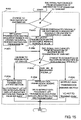
- the DRC/DSC judging section 2512 determines, in DSC signal change judgment ( FIG. 15 : P- 2030 ) and DRC signal change judgment ( FIG.
- the DSC signal change judgment refers to judgment on whether the DSC signal has changed from designation of another BS to designation of the own BS.
- the DRC signal change judgment refers to judgment on whether the DRC signal has changed from designation of another BS to designation of the own BS. For example, when it is assumed that the communication terminal apparatus 100 - 1 is in the position (a) for a sufficiently long time, it is judged in the DSC signal change judgment ( FIG. 15 : P- 2030 ) that “the own BS is designated originally” and processing in step P- 2032 is executed.
- step P- 2032 the communication connection apparatus 200 - 1 sets a latest transmission-waiting sequence number as an invalid value ( FIG. 15 : P- 2032 ). Since it is judged in the DRC signal change judgment ( FIG. 15 : P- 2033 ) that “the own BS is designated originally”, the DRC/DSC judging section 2512 instructs the data transmission judging section 2517 “(B) to extract data following last transmission data from the data accumulating section and transmit the data” ( FIG. 15 : P- 2035 ).
- the DRC/DSC signal message ( FIG. 9( c )) is created from the DRC signal and the DSC signal and transmitted to the communication control apparatus 300 in processing ( FIG. 14 : P- 205 ) in the data receiving section 2511 ( FIG. 23 : 8111 ).
- the sequence number set as the invalid value is substituted in the “latest transmission-waiting sequence number” of the DRC/DSC signal message ( FIG. 9( c )) on the basis of determination in the processing of ( FIG. 15 : P- 2032 ).
- step P- 2032 is executed. Since it is judged in the DRC signal change judgment ( FIG. 15 : P- 2033 ) that “another BS is designated originally”, the DRC/DSC judging section 2512 instructs the data transmission judging section 2517 “(C) not to transmit data” in P- 2036 in FIG. 15 .
- Transfer of the DRC signal and the DSC signal to the communication control apparatus 300 is carried out as in (3) ( FIG. 23 : 8113 ).
- the sequence number set as the invalid value is substituted in the “latest transmission-waiting sequence number” of the DRC/DSC signal message ( FIG. 9( c )) ( FIG. 15 : P- 2032 ).
- the communication control apparatus 300 judges content of data received through the data receiving section 3411 ( FIG. 19 : P- 301 and P- 302 ). Since the content is a DRC/DSC signal message, the communication control apparatus 300 transfers the DRC/DSC signal message to the DRC/DSC judging section 3412 .
- the DRC/DSC judging section 3412 judges the “latest transmission-waiting sequence number” of the DRC/DSC signal message ( FIG. 9( c )) ( FIG. 20 : P- 3030 ). Since the invalid value is set in the “latest transmission-waiting sequence number” by the processing in (3) and (4), ( FIG. 20 : P- 3032 ) is executed.
- Both the DRC signal and the DSC signal have content indicating the communication connection apparatus 200 - 1 . Therefore, the communication connection apparatus 200 - 1 is determined as a transmission destination ( FIG. 20 : P- 3032 and P- 3033 ). In step P- 3034 in FIG. 20 , the communication control apparatus 300 instructs the data transmission judging section 3417 to transmit data to the communication connection apparatus 200 - 1 .
- the communication control apparatus 300 receives data from the ISP 500 in the IP network transmission/reception section 3401 through the IP network 400 ( FIG. 22 : P- 310 ).
- the IP network transmission/reception section 3401 transfers the data received to the data transmission judging section 3417 .
- the data transmission judging section 3417 stores the data in the data accumulating section 3415 ( FIG. 22 : P- 312 ).
- the data transmission judging section 3417 determines the communication connection apparatus 200 at a communication destination ( FIG. 22 : P- 313 ) in accordance with an instruction based on a result of the judgment in (5), reads out the data from the data accumulating section 3415 , and transmits the data to the communication connection apparatus 200 determined via the data transmitting section 3418 ( FIG. 22 : P- 314 ).
- the data transmission judging section 3417 transmits data # 1 to # 15 and data # 16 to # 40 . Since the DRC signal and the DSC signal generated in (1) designate the same communication connection apparatus 200 - 1 , judging from the result in (5), only the communication connection apparatus 200 - 1 is an object of data transmission ( FIG. 23 : 8120 and 8121 ).
- the communication connection apparatus 200 - 1 receives data (first communication data) in the IP network transmission/reception section 2502 from the communication control apparatus 300 ( FIG. 17 : P- 211 ).
- the IP network transmission/reception section 2502 transfers the data to the data transmission judging section 2517 .
- the data transmission judging section 2517 stores the data in the data accumulating section 2515 ( FIG. 17 : P- 212 ) and determines a method of transmitting data to the communication terminal apparatus 100 on the basis of the result of judgment and the instruction in (3) ( FIG. 17 : P- 213 and P- 214 ). Since the DRC signal created in (1) designates the communication connection apparatus 200 - 1 , the data transmission judging section 2517 extracts data from the data accumulating section 2515 such that sequence numbers are continuous and transmits the data to the communication terminal apparatus 100 - 1 ( FIG. 17 : P- 215 , FIG. 23 : 8130 and 8131 ). A transfer rate of the data transmission to the communication terminal apparatus 100 - 1 changes according to a state of a radio section.
- the data is divided into, for example, data # 1 to # 5 and data # 6 to # 10 and transmitted for a radio signal.
- the data to be transmitted for example, in accordance with a format in FIG. 8 , the data # 1 to # 5 are included in the data body 013 and data # 1 is included in the leading sequence number 611 .
- timing of data reception from the communication control apparatus 300 ( FIG. 23 : 8120 and 8121 ) and timing of data transmission to the communication terminal apparatus 100 - 1 ( FIG. 23 : 8130 and 8131 ) do not always coincide with each other. It is assumed that data up to data # 25 are transmitted to the communication terminal apparatus 100 - 1 .
- the communication terminal apparatus 100 - 1 receives the data from the communication connection apparatus 200 - 1 in the radio processing section 1502 ( FIG. 12 : P- 111 ).
- the radio processing section 1502 transfers the data to the sequence number judging section 1512 through the data receiving section 1511 .
- the sequence number judging section 1512 checks a sequence number ( FIG. 8 : 611 ) granted to a header of the data ( FIG. 12 : P- 112 ).
- the processing in (7) since the data with the continuous sequence numbers are transmitted from the communication connection apparatus 200 - 1 , for example, it is judged that there is no loss unless data is lost in the radio section (P- 113 : N) and the data is transferred to the application processing section 1501 ( FIG.
- step P- 115 may be performed after a data group with continuous sequence numbers is formed ( FIG. 12 : P- 114 ).
- the application processing section 1501 performs appropriate application processing on the basis of the data received.
- the communication terminal apparatus 100 moves from the position (a) to the position (b) in FIG. 1 .
- the communication terminal apparatus 100 - 2 performs communication with both the communication connection apparatuses 200 - 1 and 200 - 2 .
- the DRC value is not updated and keeps the value in (1).
- the DSC value continues to indicate the communication connection apparatus 200 - 1 .
- the DRC value indicates the communication control apparatus 200 - 1 (BS 1 ) and the DSC value indicates the communication control apparatus 200 - 2 (BS 2 ).
- the communication connection apparatus 200 - 1 sets a latest transmission-waiting sequence number as a leading sequence number waiting for transmission ( FIG. 15 : P- 2031 ).
- the leading sequence number waiting for transmission is a sequence number (# 26 ) following the data (# 1 to # 25 ) transmitted to the communication terminal apparatus 100 . Since it is judged in the DRC signal change judgment ( FIG. 15 : P- 2033 ) that “the own BS is designated originally”, the DRC/DSC judging section 2512 instructs the data transmission judging section 2517 “(B) to extract data following last transmission data from the data accumulating section and transmit the data” in ( FIG. 15 : P- 2035 ).
- FIG. 9( c ) Creation of the DRC/DSC signal message ( FIG. 9( c ) is carried out as in (3). However, concerning the “latest transmission-waiting sequence number” of the DRC/DSC signal message ( FIG. 9( c )), a leading sequence number (e.g., # 26 ) of data waiting transmission to the communication terminal apparatus 100 is substituted in the “latest transmission-waiting sequence number” in the communication connection apparatus 200 - 1 on the basis of the determination in the processing in ( FIG. 15 : P- 2031 ) and transmitted to the communication control apparatus 300 ( FIG. 23 : 8211 ).
- a leading sequence number e.g., # 26
- Transfer of the DRC signal and the DSC signal to the communication control apparatus 300 is also carried out as in (4) ( FIG. 23 : 8213 ).
- the sequence number set as the invalid value is substituted in the “latest transmission-waiting sequence number” of the DRC/DSC signal message ( FIG. 9( c )).
- the DRC/DSC signal message including the DRC signal and the DSC signal is transferred to the DRC/DSC judging section 3412 , in the same operation as (5), the communication control apparatus 300 judges the “latest transmission-waiting sequence number” of the DRC/DSC signal message ( FIG. 9( c )) ( FIG. 20 : P- 3030 ). Since a valid value (# 26 ) is set in the “latest transmission-waiting sequence number” by the processing in (9) and (11), processing in ( FIG. 20 : P- 3031 ) is executed.
- step P- 3031 the communication control apparatus 300 calculates data lost in the communication connection apparatus 200 - 2 at the connection destination on the basis of the “latest transmission-waiting sequence number” of the DRC/DSC signal message ( FIG. 9( c )) and a sequence number of data that the communication control apparatus 300 transmitted last.
- the “latest transmission-waiting sequence number” is # 26
- the sequence number of data that the communication control apparatus 300 transmitted last is # 40 .
- the data lost in the communication connection apparatus 200 - 2 are data with the sequence numbers # 26 to # 40 .
- the communication control apparatus 300 reads out the data from the data accumulating section and transmits the data to the communication connection apparatus 200 - 2 ( FIG. 23 : 8220 ). According to this processing, preparation for transmitting the data to the communication terminal apparatus 100 without causing loss of the data is made on the data accumulating section 2515 of the communication connection apparatus 200 - 2 .
- the communication control apparatus 300 determines a transmission destination BS ( FIG. 20 : P- 3032 and P- 3033 ).
- the DRC signal indicates the communication connection apparatus 200 - 1
- the DSC signal indicates the communication connection apparatus 200 - 2 .
- the DRC/DSC judging section instructs the data transmission judging section 3417 to transmit the data to both the communication connection apparatuses 200 - 1 and 200 - 2 .
- the communication control apparatus 300 transfers data from the ISP 500 to the communication connection apparatus 200 .
- the data is transmitted to both the communication connection apparatuses 200 - 1 and 200 - 2 in the processing in the data transmission judging section 3417 ( FIG. 22 : P- 313 and P 314 , FIG. 23 : 8230 and 8231 ).
- the data transmission judging section 2517 of the communication connection apparatus 200 - 1 the data is transmitted to the communication terminal apparatus 100 - 2 ( FIG. 23 : 8240 and 8241 ) in ( FIG. 17 : P- 213 , (B) in P- 214 , and P- 215 ) on the basis of a result of the judgment of the DRC/DSC judging section 3412 in (11) ( FIG. 15 : P- 2035 ). It is assumed that, as an example, data # 26 to # 36 are transmitted.
- the communication terminal apparatus 100 - 2 transmits the data received from the communication connection apparatus 200 - 1 to the application processing section 1501 as in (8).
- the data is transmitted to the application processing section 1501 unless there is no loss in the radio section.
- the communication terminal apparatus 100 moves from the position (b) to the position (c) in FIG. 1 .
- the communication terminal apparatus 100 - 3 performs communication with only the communication connection apparatus 200 - 2 ( FIG. 23 : 830 ).
- the DRC/DSC judging section 2512 instructs the data transmission judging section 2517 “(A) to extract latest received data from the data accumulating section and transmit the data” in ( FIG. 15 : P- 2034 ).
- the data transmission judging section 2517 transmits the data of # 60 to the communication terminal apparatus 100 in 8320 in FIG. 24 .
- the data transmission judging section 2517 may transmit data older than the latest data, for example, appropriate data such as predetermined numbered data from the latest data.
- the data transmitted from the communication control apparatus 300 to the communication connection apparatus 200 - 2 in advance in (13) described above correspond to the lost data # 37 to # 40 .
- the data transmitted to both the communication connection apparatuses 200 - 1 and 200 - 2 correspond to the remaining lost data # 41 to # 59 .
- step P- 2043 in FIG. 16 is carried out.
- the Nak-processed flag ( FIG. 9( b ): 713 ) of the Nak message ( FIG. 9( b )) is set to notify that the retransmission processing has been carried out in the communication connection apparatus.
- step P- 2044 is executed.
- a message is transmitted to the communication control apparatus without setting the Nak-processed flag ( FIG. 9( b ): 713 ) of the Nak message ( FIG. 9( b )) such that retransmission is carried out in the communication control apparatus 300 (P- 2044 ).
- the communication terminal apparatus 100 - 3 receives the retransmission data, which is transmitted by the communication connection apparatus 200 - 2 in (23), in the data receiving section 1511 .
- the retransmission data is transferred to the sequence number judging section 1512 and check of a sequence number is performed ( FIG. 12 : P- 112 ).
- the loss of the data # 37 to # 59 detected in (22) form continuous data with the arriving retransmission data (P- 113 , N).
- the data with the continuous sequence numbers are transferred to the application processing section 1501 ( FIG. 12 : P- 114 and P- 115 ).
- the application processing section 1501 performs application processing on the basis of the data received.
- a DRC signal and a DSC signal may be transmitted from the communication terminal apparatus 100 anew ( FIG. 24 , 8350 to 8352 ). Processing applied to these signals is the same as the processing 8310 to 8312 described above.
- the communication connection apparatus 200 - 2 executes the processing 8320 , but the communication connection apparatus 200 - 2 does not execute the processing 8320 unless the DRC signal changes.
- the communication control apparatus 300 transfers a DRC/DSC signal message to the DRC/DSC judging section 3412 in the same operation as (13) and judges the “latest transmission-waiting sequence number” of the DRC/DSC signal message ( FIG. 9( c )) ( FIG. 20 : P- 3030 ). According to the processing in (18) and (19), since the invalid value is set in the “latest transmission-waiting sequence number”, ( FIG. 20 : P- 3032 ) is executed. Both the DRC signal and the DSC signal have content indicating the communication connection apparatus 200 - 2 (BS 2 ). Therefore, the communication connection apparatus 200 - 2 is determined as a transmission destination ( FIG. 20 : P- 3032 and P- 3033 ). The communication control apparatus 300 instructs the data transmission judging section 3417 to transmit data to the communication connection apparatus 200 - 2 ( FIG. 20 : P- 3034 ).
- the communication control apparatus 300 transmits data from the ISP 500 to the communication terminal apparatus 100 as in (6).
- the data transmission judging section 3417 stores the data received in the data accumulating section 3415 ( FIG. 22 : P- 311 and P- 312 ), determines the communication connection apparatus 200 at a destination on the basis of the instruction of the result of the judgment in (25) ( FIG. 22 : P- 313 ), and transmits the data to the communication connection apparatus 200 ( FIG. 22 : P- 314 , FIG. 24 : 8360 and 8361 ).
- the communication connection apparatus 200 - 2 transmits the data to the communication terminal apparatus 100 ( FIG. 24 : 8370 and 8371 ).
- the Nak message ( FIG. 9( b )) transmitted in the Nak message transmission processing ( FIG. 16 : P- 2043 or P- 2044 ) of the communication connection apparatus 200 in (23) is received by the communication control apparatus 300 .
- the communication control apparatus 300 judges content of the data ( FIG. 19 : P- 302 ).
- Nak message processing ( FIG. 19 : P- 304 ) is executed.
- the communication control apparatus 300 evaluates the Nak-processed flag ( FIG. 9( b ): 713 ) of the Nak message ( FIG. 9( b )) ( FIG. 21 : P- 3040 ).
- the communication control apparatus 300 judges that the retransmission processing is necessary and carries out the retransmission processing in step P- 2041 and the subsequent steps.
- the Nak message analyzing section 3414 analysis of the Nak message is carried out to specify data that should be retransmitted on the basis of a sequence number and Length ( FIG. 21 : P- 2041 ).
- the data retransmitting section 3416 extracts data from the data accumulating section 3415 and transmits the data to the data transmitting section 3418 ( FIG. 21 : P- 2043 ).
- the communication control apparatus 300 does not carry out retransmission.
- the processing in which the communication terminal apparatus 100 switches a communication destination from the communication connection apparatus 200 - 1 to the communication connection apparatus 200 - 2 is completed in the operations described above.
- the communication terminal apparatus 100 moves to be subjected to Handoff.
- the invention is also applicable to a case in which the communication terminal apparatus 100 is subjected to Handoff because of a change in a radio wave environment due to movement of an obstacle or the like or a change in a communication environment such as a congestion condition of communication.
- the communication connection apparatus 200 - 2 detects a change of a DRC signal from another BS to the own BS and transmits latest data among data accumulated to the communication terminal apparatus 100 to induce a Nak message, which is a request for retransmission from the communication terminal apparatus 100 . Since the communication connection apparatus 200 - 2 retransmits the data on the basis of a sequence number described in this Nak message, there is an advantage that the communication connection apparatus 200 - 2 does not need to learn in advance to which extent the communication terminal apparatus 100 has received the data.
- the detection of data loss and the transmission of a Nak message in the communication terminal apparatus 100 are the same as operations in the case in which data is lost in the radio section in the usual communication state. These are functions provided in the existing communication terminal apparatus 100 . Thus, there is an advantage that the invention does not require a special mechanism in the communication terminal apparatus 100 .
- the retransmission processing for data by a Nak message is carried out in the communication connection apparatus 200 closer to the communication terminal apparatus 100 rather than in the communication control apparatus 300 to reduce time required for the retransmission processing.
- FIG. 25 is an example of communication switching by a DRC signal. An example of operations in the case in which a DSC signal is not used will be explained with reference to FIG. 25 .
- FIG. 25 and the following explanation are described according to the explanation of this embodiment to facilitate understanding and do not specify a conventional technique.
- processing 910 for example, when the AT 100 is close to the BS 200 - 1 , communication data is transmitted to the AT 100 via the BS 200 - 1 in accordance with the DRC signal (processing 1110 to processing 1131 ).
- the AT 100 switches DRC to the BS 2 according to a change in received radio wave intensity and transmits the data to the BS 1 and the BS 2 (processing 1210 and 1212 ).
- the BS 1 transmits the DRC and a latest transmission-waiting sequence number (as an example, # 26 ) to the BSC (processing 1211 ).
- the BS 2 transmits the DRC and an invalid value set as the latest transmission-waiting sequence number to the BSC (processing 1213 ).
- the BSC changes a BS to be a transmission destination of the data to the BS 2 .
- the data are transmitted to the AT via the BS 2 (processing 1220 to 1240 ).
- a no-communication period appears from the time when the AT notifies the DRC change until the time when the AT receives a transmission packet from the BS 2 .
- FIGS. 26 and 27 are an example of communication switching by a DRC signal and a DSC signal. An example of operations in the case in which latest data is not transmitted from the BS 2 and a Nak message is not induced will be explained with reference to FIGS. 26 and 27 . FIGS. 26 and 27 and the following explanation are described according to the explanation of this embodiment to facilitate understanding and do not specify a conventional technique.
- Respective kinds of processing shown in FIG. 26 may be the same as the respective kinds of processing in FIG. 23 described above.
- the BS 2 receives a DRC signal and a DSC signal for selecting the own apparatus from the AT (processing 8310 )
- the BS 2 transmits packets in a buffer of the BS 2 unconditionally (processing 2320 ).
- data “ 26 and the subsequent data accumulated in processing 8250 and 8251 are transmitted to the AT.
- the AT Since the AT has already received the data # 26 to # 36 from the BS 1 in processing 8240 and 8241 , redundant data flow in a radio communication path. In this way, efficiency of use of the radio section may fall.
- a separation of redundant data and data not received is not always a separation of packets.
- Data # 36 and # 37 may be an identical packet.
- the BS 2 since the BS 2 transmits latest data among the accumulated data, it is less likely that redundant data is transmitted. When the latest data is transmitted, data received in the AT may be lost. However, it is possible to transmit the data without a loss by receiving a Nak message that requests the lost data from the AT and retransmitting the data. Moreover, a function of retransmitting lost data is given to the BS to make it possible to reduce time required for retransmission processing of the lost data.
- the invention is applicable to, for example, industries related to packet communication systems and radio communication systems.
Abstract
Description
- [Patent Document 1] JP-A-2004-343552
- [Non-patent Document 1] 3GPP2 C.S0024 cdma2000 High Rate Packet Data Air Interface Specification Version 4.0, Chapter 3.4 and Chapter 8.4
- [Non-patent Document 2] 3GPP2 C.S0024-A cdma2000 High Rate Packet Data Air Interface Specification Version 1.0, Chapter 11.7.6.1.5 and Chapter 14.2.1.3.3.3.
Claims (8)
Applications Claiming Priority (2)
| Application Number | Priority Date | Filing Date | Title |
|---|---|---|---|
| JP2005-350950 | 2005-12-05 | ||
| JP2005350950A JP4639145B2 (en) | 2005-12-05 | 2005-12-05 | Communication method and communication system |
Publications (2)
| Publication Number | Publication Date |
|---|---|
| US20070270146A1 US20070270146A1 (en) | 2007-11-22 |
| US7720480B2 true US7720480B2 (en) | 2010-05-18 |
Family
ID=38131376
Family Applications (1)
| Application Number | Title | Priority Date | Filing Date |
|---|---|---|---|
| US11/633,418 Expired - Fee Related US7720480B2 (en) | 2005-12-05 | 2006-12-05 | System and method for reducing a no-communication period during hand-off |
Country Status (3)
| Country | Link |
|---|---|
| US (1) | US7720480B2 (en) |
| JP (1) | JP4639145B2 (en) |
| CN (2) | CN1980412B (en) |
Families Citing this family (10)
| Publication number | Priority date | Publication date | Assignee | Title |
|---|---|---|---|---|
| WO2008123127A1 (en) | 2007-03-20 | 2008-10-16 | Nec Corporation | Base station, mobile communication system using the base station, and data transfer method |
| KR100892069B1 (en) * | 2007-08-16 | 2009-04-07 | 한국전자통신연구원 | The method, apparatus and system for network resource reservation considering terminal speed and mobile terminal |
| US7751839B2 (en) * | 2007-11-08 | 2010-07-06 | Motorola, Inc. | Method and system for bandwidth optimization in a communication network |
| JP5104260B2 (en) * | 2007-12-04 | 2012-12-19 | 富士通株式会社 | Mobile communication system |
| JP5817387B2 (en) * | 2011-09-26 | 2015-11-18 | 日本電気株式会社 | Communication apparatus and communication method |
| JP6142920B2 (en) | 2013-05-10 | 2017-06-07 | 富士通株式会社 | Wireless communication system, mobile station, base station, and wireless communication method |
| JP5934276B2 (en) * | 2014-03-28 | 2016-06-15 | アンリツ株式会社 | Test apparatus and test method |
| JP6481711B2 (en) * | 2017-05-11 | 2019-03-13 | 富士通コネクテッドテクノロジーズ株式会社 | Wireless communication system, mobile station, base station, and wireless communication method |
| CN112154618B (en) * | 2018-05-23 | 2023-10-13 | 兴和株式会社 | Communication system, control system, and communication device |
| US11139929B2 (en) * | 2018-07-11 | 2021-10-05 | Qualcomm Incorporated | Enhanced reliability techniques for shared spectrum |
Citations (8)
| Publication number | Priority date | Publication date | Assignee | Title |
|---|---|---|---|---|
| US20030007480A1 (en) * | 2001-06-11 | 2003-01-09 | Samsung Electronics Co., Ltd. | Data retransmission apparatus and method in a mobile communication system |
| US20030007466A1 (en) * | 2001-07-06 | 2003-01-09 | Tao Chen | Method and apparatus for predictive scheduling in a bi-directional communication system |
| US20040147236A1 (en) * | 2001-05-22 | 2004-07-29 | Stefan Parkvall | Method and system of retransmission |
| US20040192308A1 (en) * | 2003-03-24 | 2004-09-30 | Jun-Sung Lee | System and method for retransmitting uplink data from a mobile terminal in a soft handover region in an asynchronous CDMA mobile communication system servicing an enhanced uplink dedicated transport channel |
| JP2004343552A (en) | 2003-05-16 | 2004-12-02 | Ntt Docomo Inc | Receiver, transmitter and program |
| US20060147236A1 (en) * | 2003-12-09 | 2006-07-06 | Canon Kabushiki Kaisha | Printing control apparatus and printing control method |
| US20070022396A1 (en) * | 2005-07-20 | 2007-01-25 | Attar Rashid A A | Method and apparatus for expanded data rate control indices in a wire less communication system |
| US20070042781A1 (en) * | 2005-08-16 | 2007-02-22 | Qualcomm Incorporated | Methods and systems for server selection during feedback channel impairment in wireless communications |
Family Cites Families (11)
| Publication number | Priority date | Publication date | Assignee | Title |
|---|---|---|---|---|
| FI102654B1 (en) * | 1996-02-22 | 1999-01-15 | Nokia Mobile Phones Ltd | A method for changing a base station in an ATM network radio extension |
| JP3794663B2 (en) * | 1998-03-13 | 2006-07-05 | 株式会社東芝 | Wireless communication system |
| KR100370527B1 (en) * | 1998-07-15 | 2003-01-30 | 가부시키가이샤 히타치세이사쿠쇼 | Method of switching busy line in mobile communication network |
| US6842619B2 (en) * | 2001-07-19 | 2005-01-11 | Ericsson Inc. | Telecommunications system and method for load sharing within a code division multiple access 2000 network |
| US6865389B2 (en) * | 2001-09-05 | 2005-03-08 | Telefonaktiegolaget Lm Ericsson | System and method for a virtual soft handover in a high data rate network based on data transmission information |
| JP2003153327A (en) * | 2001-11-12 | 2003-05-23 | Matsushita Electric Ind Co Ltd | Radio communication system, method of executing hand over used for it, and radio communication terminal |
| US20040085957A1 (en) * | 2002-11-01 | 2004-05-06 | Sanjeev Verma | Apparatus and method for providing IP connectivity to mobile nodes during handover |
| KR20040061790A (en) * | 2002-12-31 | 2004-07-07 | 에스케이 텔레콤주식회사 | Method and System for Recovering from Hand-off fail for Use in CDMA 2000 1x EV-DO System |
| US7206598B2 (en) * | 2003-07-25 | 2007-04-17 | Qualcomm Incorporated | Method and apparatus for a control channel power allocation in a communication system |
| JP4335724B2 (en) * | 2004-03-26 | 2009-09-30 | 富士通株式会社 | Transmission packet compensation system and transmission packet compensation method |
| US7821995B2 (en) * | 2004-09-30 | 2010-10-26 | Alcatel-Lucent Usa Inc. | Active session mobility solution for radio link protocol |
-
2005
- 2005-12-05 JP JP2005350950A patent/JP4639145B2/en not_active Expired - Fee Related
-
2006
- 2006-09-25 CN CN2006101393516A patent/CN1980412B/en not_active Expired - Fee Related
- 2006-09-25 CN CN201010167507A patent/CN101848502A/en active Pending
- 2006-12-05 US US11/633,418 patent/US7720480B2/en not_active Expired - Fee Related
Patent Citations (8)
| Publication number | Priority date | Publication date | Assignee | Title |
|---|---|---|---|---|
| US20040147236A1 (en) * | 2001-05-22 | 2004-07-29 | Stefan Parkvall | Method and system of retransmission |
| US20030007480A1 (en) * | 2001-06-11 | 2003-01-09 | Samsung Electronics Co., Ltd. | Data retransmission apparatus and method in a mobile communication system |
| US20030007466A1 (en) * | 2001-07-06 | 2003-01-09 | Tao Chen | Method and apparatus for predictive scheduling in a bi-directional communication system |
| US20040192308A1 (en) * | 2003-03-24 | 2004-09-30 | Jun-Sung Lee | System and method for retransmitting uplink data from a mobile terminal in a soft handover region in an asynchronous CDMA mobile communication system servicing an enhanced uplink dedicated transport channel |
| JP2004343552A (en) | 2003-05-16 | 2004-12-02 | Ntt Docomo Inc | Receiver, transmitter and program |
| US20060147236A1 (en) * | 2003-12-09 | 2006-07-06 | Canon Kabushiki Kaisha | Printing control apparatus and printing control method |
| US20070022396A1 (en) * | 2005-07-20 | 2007-01-25 | Attar Rashid A A | Method and apparatus for expanded data rate control indices in a wire less communication system |
| US20070042781A1 (en) * | 2005-08-16 | 2007-02-22 | Qualcomm Incorporated | Methods and systems for server selection during feedback channel impairment in wireless communications |
Non-Patent Citations (4)
| Title |
|---|
| 3GPP2 C.S0024 cdma2000 High Rate Packet Data Air Interface Specification Version 4.0, Chapter 3.4 and Chapter 8.4, pp. 3-5 and 3-11. |
| 3GPP2 C.S0024 Version 4.0 MAC Layer, Chapter 8.4, pp. 8-35-8-50. |
| 3GPP2 C.S0024-A cdma2000 High Rate Packet Data Air Interface Specification Version, Chapter 11.7.6.1.5 and Chapter 14.2.1.3.3.3., pp. 11-102-11-108. |
| 3GPP2 C.S0024-A v1.0 Subtype 2 Physical Layer, Chapter 14.2.1.3.3, pp. 14-26-14-28. |
Also Published As
| Publication number | Publication date |
|---|---|
| JP2007158699A (en) | 2007-06-21 |
| CN1980412B (en) | 2010-06-02 |
| JP4639145B2 (en) | 2011-02-23 |
| CN1980412A (en) | 2007-06-13 |
| CN101848502A (en) | 2010-09-29 |
| US20070270146A1 (en) | 2007-11-22 |
Similar Documents
| Publication | Publication Date | Title |
|---|---|---|
| US7720480B2 (en) | System and method for reducing a no-communication period during hand-off | |
| JP4858690B2 (en) | Mobile communication system and data transmission method during handover | |
| US20180255485A1 (en) | Method and system for base station change of packet switched communications in a mobile communications system | |
| EP1881711B1 (en) | Control of the purging of a node B by the serving radio network controller | |
| EP2123085B1 (en) | Selective packet forwarding for lte mobility | |
| JP4335724B2 (en) | Transmission packet compensation system and transmission packet compensation method | |
| US8379610B2 (en) | System and method of unacknowledged network layer service access point identifier (NSAPI) recovery in sub-network dependent convergence protocol (SNDCP) communication | |
| JP2005510950A (en) | Retransmission method and retransmission system | |
| CN101374349A (en) | Handover method and apparatus in a wireless telecommunications network | |
| US20080084846A1 (en) | Wireless communication system, wireless base station, and wireless communication control method | |
| KR20140097610A (en) | Method and apparatus for sending radio link control status report for sending in a communication system based on a multi-radio access technologies | |
| JP2003047037A (en) | Communication system and hand-over control method | |
| WO2016095198A1 (en) | Apparatus, system and method for preventing tcp connection interruption | |
| US20120195287A1 (en) | Communication method using duplicated acknowledgement | |
| JP4635816B2 (en) | Mobile communication system, source node, target node, handover method used therefor, and program thereof | |
| US20080132234A1 (en) | Apparatus and method for utilizing the transport layer to provide measurement opportunities for the physical layer in a multi-mode network | |
| US20130344870A1 (en) | Base station, mobile communication system using the base station, and data transfer method | |
| KR20090046603A (en) | Apparatus and method for traffic forwarding in wireless communication system | |
| JP2010525762A (en) | Changing the serving access point for the forward and reverse links | |
| US20050237976A1 (en) | Data preservation |
Legal Events
| Date | Code | Title | Description |
|---|---|---|---|
| AS | Assignment |
Owner name: HITACHI COMMUNICATION TECHNOLOGIES, LTD., JAPAN Free format text: ASSIGNMENT OF ASSIGNORS INTEREST;ASSIGNORS:SUZUKI, TAKAAKI;LOU, YI;AOE, HIDEO;REEL/FRAME:019344/0832 Effective date: 20070425 Owner name: HITACHI COMMUNICATION TECHNOLOGIES, LTD.,JAPAN Free format text: ASSIGNMENT OF ASSIGNORS INTEREST;ASSIGNORS:SUZUKI, TAKAAKI;LOU, YI;AOE, HIDEO;REEL/FRAME:019344/0832 Effective date: 20070425 |
|
| FEPP | Fee payment procedure |
Free format text: PAYOR NUMBER ASSIGNED (ORIGINAL EVENT CODE: ASPN); ENTITY STATUS OF PATENT OWNER: LARGE ENTITY |
|
| AS | Assignment |
Owner name: HITACHI, LTD.,JAPAN Free format text: MERGER;ASSIGNOR:HITACHI COMMUNICATION TECHNOLOGIES, LTD.;REEL/FRAME:023758/0625 Effective date: 20090701 Owner name: HITACHI, LTD., JAPAN Free format text: MERGER;ASSIGNOR:HITACHI COMMUNICATION TECHNOLOGIES, LTD.;REEL/FRAME:023758/0625 Effective date: 20090701 |
|
| FPAY | Fee payment |
Year of fee payment: 4 |
|
| FEPP | Fee payment procedure |
Free format text: MAINTENANCE FEE REMINDER MAILED (ORIGINAL EVENT CODE: REM.) |
|
| LAPS | Lapse for failure to pay maintenance fees |
Free format text: PATENT EXPIRED FOR FAILURE TO PAY MAINTENANCE FEES (ORIGINAL EVENT CODE: EXP.) |
|
| STCH | Information on status: patent discontinuation |
Free format text: PATENT EXPIRED DUE TO NONPAYMENT OF MAINTENANCE FEES UNDER 37 CFR 1.362 |
|
| FP | Lapsed due to failure to pay maintenance fee |
Effective date: 20180518 |