US7716566B2 - Data error control - Google Patents
Data error control Download PDFInfo
- Publication number
- US7716566B2 US7716566B2 US11/187,737 US18773705A US7716566B2 US 7716566 B2 US7716566 B2 US 7716566B2 US 18773705 A US18773705 A US 18773705A US 7716566 B2 US7716566 B2 US 7716566B2
- Authority
- US
- United States
- Prior art keywords
- entries
- channels
- parity
- data
- reconstructed
- Prior art date
- Legal status (The legal status is an assumption and is not a legal conclusion. Google has not performed a legal analysis and makes no representation as to the accuracy of the status listed.)
- Active, expires
Links
Images


Classifications
-
- H—ELECTRICITY
- H04—ELECTRIC COMMUNICATION TECHNIQUE
- H04L—TRANSMISSION OF DIGITAL INFORMATION, e.g. TELEGRAPHIC COMMUNICATION
- H04L1/00—Arrangements for detecting or preventing errors in the information received
- H04L1/004—Arrangements for detecting or preventing errors in the information received by using forward error control
- H04L1/0045—Arrangements at the receiver end
-
- G—PHYSICS
- G06—COMPUTING OR CALCULATING; COUNTING
- G06F—ELECTRIC DIGITAL DATA PROCESSING
- G06F11/00—Error detection; Error correction; Monitoring
- G06F11/07—Responding to the occurrence of a fault, e.g. fault tolerance
- G06F11/08—Error detection or correction by redundancy in data representation, e.g. by using checking codes
- G06F11/10—Adding special bits or symbols to the coded information, e.g. parity check, casting out 9's or 11's
- G06F11/1076—Parity data used in redundant arrays of independent storages, e.g. in RAID systems
- G06F11/1092—Rebuilding, e.g. when physically replacing a failing disk
-
- H—ELECTRICITY
- H03—ELECTRONIC CIRCUITRY
- H03M—CODING; DECODING; CODE CONVERSION IN GENERAL
- H03M13/00—Coding, decoding or code conversion, for error detection or error correction; Coding theory basic assumptions; Coding bounds; Error probability evaluation methods; Channel models; Simulation or testing of codes
- H03M13/03—Error detection or forward error correction by redundancy in data representation, i.e. code words containing more digits than the source words
- H03M13/05—Error detection or forward error correction by redundancy in data representation, i.e. code words containing more digits than the source words using block codes, i.e. a predetermined number of check bits joined to a predetermined number of information bits
- H03M13/11—Error detection or forward error correction by redundancy in data representation, i.e. code words containing more digits than the source words using block codes, i.e. a predetermined number of check bits joined to a predetermined number of information bits using multiple parity bits
-
- H—ELECTRICITY
- H03—ELECTRONIC CIRCUITRY
- H03M—CODING; DECODING; CODE CONVERSION IN GENERAL
- H03M13/00—Coding, decoding or code conversion, for error detection or error correction; Coding theory basic assumptions; Coding bounds; Error probability evaluation methods; Channel models; Simulation or testing of codes
- H03M13/37—Decoding methods or techniques, not specific to the particular type of coding provided for in groups H03M13/03 - H03M13/35
- H03M13/373—Decoding methods or techniques, not specific to the particular type of coding provided for in groups H03M13/03 - H03M13/35 with erasure correction and erasure determination, e.g. for packet loss recovery or setting of erasures for the decoding of Reed-Solomon codes
-
- H—ELECTRICITY
- H03—ELECTRONIC CIRCUITRY
- H03M—CODING; DECODING; CODE CONVERSION IN GENERAL
- H03M13/00—Coding, decoding or code conversion, for error detection or error correction; Coding theory basic assumptions; Coding bounds; Error probability evaluation methods; Channel models; Simulation or testing of codes
- H03M13/37—Decoding methods or techniques, not specific to the particular type of coding provided for in groups H03M13/03 - H03M13/35
- H03M13/3746—Decoding methods or techniques, not specific to the particular type of coding provided for in groups H03M13/03 - H03M13/35 with iterative decoding
-
- H—ELECTRICITY
- H04—ELECTRIC COMMUNICATION TECHNIQUE
- H04L—TRANSMISSION OF DIGITAL INFORMATION, e.g. TELEGRAPHIC COMMUNICATION
- H04L1/00—Arrangements for detecting or preventing errors in the information received
- H04L1/004—Arrangements for detecting or preventing errors in the information received by using forward error control
- H04L1/0041—Arrangements at the transmitter end
-
- H—ELECTRICITY
- H04—ELECTRIC COMMUNICATION TECHNIQUE
- H04L—TRANSMISSION OF DIGITAL INFORMATION, e.g. TELEGRAPHIC COMMUNICATION
- H04L1/00—Arrangements for detecting or preventing errors in the information received
- H04L1/004—Arrangements for detecting or preventing errors in the information received by using forward error control
- H04L1/0056—Systems characterized by the type of code used
- H04L1/0057—Block codes
-
- H—ELECTRICITY
- H04—ELECTRIC COMMUNICATION TECHNIQUE
- H04L—TRANSMISSION OF DIGITAL INFORMATION, e.g. TELEGRAPHIC COMMUNICATION
- H04L1/00—Arrangements for detecting or preventing errors in the information received
- H04L2001/0092—Error control systems characterised by the topology of the transmission link
- H04L2001/0096—Channel splitting in point-to-point links
Definitions
- This specification relates to error control for data that is subject to corruptions or erasures.
- Various techniques are used for error control of data in the face of errors and erasures in the data.
- a number of techniques are applicable to data that is represented or representable as N channels.
- redundant data in the form of parity is also computed to form additional channels, and the original and redundant channels are distributed each to a separate storage system. If one of the storage systems fails, and therefore represents an “erasure” of the data for the corresponding channel, a redundant parity channel can be used to reconstruct the data.
- This general approach is used in various variants of RAID (Redundant Array of Inexpensive Disks) systems.
- ECCs Error Correcting Codes
- Parity approaches have also been used for multiple channels of streaming data, such as parallel bit streams stored on and retrieved from a magnetic tape storage. For example, a stream of parity bits are computed and stored with the data on the tape, with each parity bit being computed from a “stripe” of data bits from the data streams, such as from a stripe across corresponding bits of all the channels. In some approaches, multiple streams of parity bits are computed using diagonal stripes through the data (i.e., using different time offsets for each channel when computing a parity value). With multiple parity streams, one or more errors can be detected, and corrected under certain conditions.
- a method for data error correction includes, in successive iterations, reconstructing entries of one or more of N+M channels of encoded data, the channels representing N channels of source data and satisfying parity equation such that at least some of the entries contribute to M of the parity equations. At each iteration, one or more of the parity equations are applied to reconstruct at least one of the entries in each of the one or more of the N+M channels.
- M can be 2, 3, 4, 5, or any larger integer.
- a method for data error correction includes receiving at least some channels of N+M channels of encoded data that represent N channels of source data, wherein each channel of the N+M channels of encoded data includes a series of entries.
- the N+M channels of encoded data satisfy parity equations such at least some entries contribute to M of the parity equations.
- Entries of one or more channels of the N+M channels of encoded data are iteratively reconstructed, at each iteration applying one or more of the parity equations to received or reconstructed entries of the N+M channels of encoded data to reconstruct an entry in each of the one or more of the N+M channels.
- Iteratively reconstructing the entries includes reconstructing entries in two or more of the channels.
- reconstructing at least some of the entries in the two or more channels uses an entry in another of the two or more channels reconstructed in that iteration.
- Reconstructing each entry includes applying a single one of the parity equations to received or reconstructed entries.
- Reconstructing at least some entries includes applying a parity equation to a reconstructed entry.
- Iteratively reconstructing the entries includes at each iteration reconstructing an entry in one of the one or more channels to be reconstructed using a combination of the parity equations which combination is independent of entries in at least one other of the one or more channels to be reconstructed.
- the combination of parity equations is independent of entries in all others of the one or more channels to be reconstructed.
- the one or more channels to be reconstructed includes M channels to be reconstructed, and the combination of parity equations is independent of entries in M ⁇ 1 of the channels.
- the method includes determining channels of the N+M channels that were not received, and iteratively reconstructing entries in the one or more channels includes reconstructing entries in channels that were not received.
- the method includes detecting errors in entries in the received channels, and iteratively reconstructing entries in the one or more channels includes reconstructing entries in channels in which the errors were detected.
- a method in another aspect, includes receiving at least some channels of N+M channels of encoded data that represent N channels of source data, wherein each channel of the N+M channels of encoded data includes a series of entries, the N+M channels of encoded data satisfying parity equations such that each entry in at least some of the N+M channels of encoded data contributes to at least some of the parity equations. At least two of the N+M channels are reconstructed from the received channels, by forming combinations of the parity equations to reconstruct entries in the channels being reconstructed, each combination of parity equations being independent of all entries in at least some of the channels being reconstructed.
- Reconstructing the at least two channels includes reconstructing each of the at least two channels independently of other of the at least two channels.
- Reconstructing the at least two channels includes reconstructing said channels concurrently.
- Reconstructing the at least two channels includes reconstructing said channels in sequence.
- a method in another aspect, includes receiving encoded data, including receiving at least N channels of encoded data of N+M channels of encoded data that represent N channels of source data, and correcting errors in the received encoded data by using the received at least N channels of encoded data to correct errors in at least other of the channels of encoded data.
- Each channel of the N+M channels of encoded data including a series of entries, the channels of encoded data satisfying parity equations such that each entry in at least some of the N+M channels of encoded data contributes to at least M independent parity equations.
- Correcting errors in the received encoded data includes using the received at least N channels of encoded data to correct errors in M other of the channels of encoded data.
- M is at least three, is at least four, or is at least five.
- Receiving the at least N channels of encoded data includes receiving said channels without error.
- Receiving the encoded data includes receiving one or more channels other than the received N channels with errors.
- Receiving the one or more channels with errors includes receiving said channels with corruption errors.
- Receiving the one or more channels with errors includes receiving said channels with erasure errors.
- Receiving the encoded data includes not receiving one or more channels other than the received N channels.
- Correcting the errors in the received encoded data includes determining a set of error-free channels, the set of error-free channels including at least N channels of encoded data that were received without error.
- Correcting the errors further includes determining entries in a set of repaired channels, the set of repaired channels being distinct from the set of error-free channels.
- Correcting the errors further includes determining entries in a set of repaired channels, including applying the parity equations to entries in the set of channels of encoded data that were received without error to determine entries in a corrected set of channels of data, the corrected set of channels not in the set of channels of encoded data that were received without error.
- Applying the parity equations to entries in the set of channels includes iterating over successive entries in the series of entries in at least one of the repaired channels.
- Iterating over the successive entries includes, for each successive entry, applying at least one of the parity equations to determine said entry.
- Correcting the errors further includes iterating over entries in the least m other channels of encoded data.
- Iterating over the entries includes iteratively determining each entry using one or more of the parity equations.
- Determining each entry using one or more of the parity equations includes using one or more of the parity equations in a combination that does not depend on one or more of the at least m other channels of encoded data.
- a method in another aspect, includes accepting source data, and representing the source data as N channels of source data, each including a series of I entries.
- the N channels of source data are encoded to form N+M channels of encoded data, the channels of encoded data satisfying at least M ⁇ I independent parity equations, at least I entries of some of the channels of encoded data each being an argument to at least M of the parity equations.
- Encoding the N channels includes augmenting the N channels of source data with M channels of parity data, each including a series of at least I entries.
- Each entry of the N channels of source data is an argument to M of the parity equations.
- At least some of the M channels of parity data at least I entries in the channel are each an argument to at least two of the parity equations.
- At least some of the M channels of parity data at least I entries in the channel are each an argument to at least M of the parity equations.
- Each channel of parity data is associated with a class of parity equations, the class of parity equations being associated with a set of the N+M channels that contribute arguments to the parity equations and relative offsets of entries in the channels that contribute to any of the equations in the class.
- the offsets for at least some of the classes of parity equations are such that the relative offsets of the entries form a diagonal line across the N channels of source data when arranged as an array of N columns by I rows.
- Representing the source data as N channels of source data includes concatenating a series of extra entries with the series of I entries.
- Encoding the N channels of source data to form N+M channels of encoded data includes applying at least some of the parity equations to extra entries and entries representing the source data to determine entries of the encoded data.
- the extra entries have zero values.
- Encoding the data further includes determining the extra entries as a key to the encoded data.
- the encoding of the data enables reconstruction of the source data from any N of the N+M channels of encoded data.
- the encoding of the data enables detection of errors in M ⁇ 1 of the N+M channels of encoded data.
- Accepting the source data includes accepting the source data as one or more data streams, representing the one or more data streams as N channels, and encoding the data includes processing the accepted data using a cross-convolutional encoding approach across the N channels to produce the N+M channels of encoded data as a stream of data.
- a method for data error protection includes accepting source data and representing the source data as N channels of source data, each including a series of I entries.
- the N channels of source data are encoded to form N+M channels of encoded data, the channels of encoded data satisfying at least M ⁇ I independent parity equations, at least I entries of some of the channels of encoded data each being an argument to at least M of the parity equations.
- the N+M channels of encoded data are handled, and then entries in one or more channels of the N+M channels of encoded data are iteratively reconstructed. At each iteration one or more of the parity equations are applied to received or reconstructed entries of the N+M channels of encoded data to reconstruct an entry in each of the one or more of the N+M channels.
- the source data is recovered using the reconstructed entries.
- a method in another aspect, includes representing the source data as N channels of source data, each including a series of I entries.
- the N channels of source data are encoded to form N+M channels of encoded data, the channels of encoded data satisfying at least M ⁇ I independent parity equations, at least I entries of some of the channels of encoded data each contributing to at least M of the parity equations. Errors are introduced into at least M/2 of the N+M channels, and the source data is recovered from the channels.
- Encoding the N channels includes augmenting the N channels of source data with M channels of parity data.
- the channels are transmitted over different paths.
- Transmitting the channels over different paths includes transmitting the channels over different communication links.
- Transmitting the channels over different paths includes transmitting the channels at different times.
- Transmitting the channels over different paths includes transmitting the channels in different packets.
- the channels are stored in different storage devices.
- Recovering the source data includes correcting errors in the channels of encoded data, including using least N channels of encoded data to correct errors in at least m>M/2 other of the channels of encoded data.
- a method for distributed storage of data includes representing the source data as N channels of source data, each including a series of I entries.
- the N channels of source data are encoded to form N+M channels of encoded data, the channels of encoded data satisfying at least M ⁇ I independent parity equations, at least I entries of some of the channels of encoded data each being an argument to at least M of the parity equations.
- the N+M channels of encoded data are distributed to separate storages. At least some of the N+M channels of encoded data are retrieved from the separate storages.
- the entries in one or more channels of the N+M channels of encoded data are iteratively reconstructed using the retrieved channels, at each iteration applying one or more of the parity equations to received or reconstructed entries of the N+M channels of encoded data to reconstruct an entry in each of the one or more of the N+M channels.
- the source data is recovered using the reconstructed entries.
- N of data fields each contain I of items.
- the data fields are distributed across the storage or communication system so as to contain typical errors or failures in as few fields as possible.
- An encoder generates M of parity fields.
- Each item of the generated parity fields is the result of simple exclusive-or operations on one item from one or more data fields and possibly one item from one or more of the other parity fields.
- the generated parity field operations are unique within the parity field, such that no two parity field operations within the same parity field share any data or parity item.
- the generated parity fields are independent of each of the other parity fields, such that no two parity field operations from two different parity fields share more than one item.
- the generated parity fields have a sufficient number of items such that the generated parity field's operations include every item of every data field.
- the generated parity fields have additional items, the additional items being the result of exclusive-or operations which include fewer than N data items, such that errors in data fields which are not included in those operations have no effect on the result of said operation.
- a decoder begins with the additional items of the generated parity fields, and regenerates as many as M missing or corrupted fields of either data or parity, item by item, using combinations of correct and previously corrected items as inputs to a cross-convolution of the M independent parity equations, to solve for and correct each missing or corrupted item in turn.
- Each item is a bit and the exclusive-or parity operations are bit-wise.
- Each item includes multiple bits, and the exclusive-or operations are bit-wise on one of the bits in each item is performed in parallel.
- parity fields are arranged alongside the data fields, and the parity equations of each parity field are generated along a straight line through items in both parity and data fields.
- Each parity operation to generate a parity item contains one item from each of the other parity fields.
- a first parity field is generated using parity operations including only data fields, and subsequent parity fields are generated using parity operations including data fields and the previous parity field.
- the subsequent parity fields have only items whose equations include data fields, but do not have items whose equations cover only the additional items in previous parity fields, and wherein the previous additional parity items which are not included in the subsequent parity field are stored or transmitted using some reliable means.
- parity fields are arranged alongside the data fields, and the parity equations of each parity field are generated along a line which is straight through items in the data fields, but bends to an angle that is perpendicular to the parity fields.
- the decoder uses an equation at the beginning or end of the data and parity fields, that include only correct items and one incorrect item, to correct the incorrect item.
- the decoder uses another equation which includes only correct items, the previously corrected incorrect item, and one more incorrect item, to correct the second incorrect item.
- the decoder proceeds through as many equations are necessary to correct one incorrect item from each data or parity field, establishing a new boundary of correct items.
- the decoder repeats the above sequence to move the boundary of correct items through the data and parity fields, until all incorrect items in all fields have been corrected.
- an encoder enables correction of up to two incorrect fields.
- the encoder uses two parity fields, and the parity fields are arranged alongside the data fields, and the parity equations of each parity field are generated along a line which is straight through items in the data fields.
- a decoder combines a pair of equations at the beginning of the fields, which cross at one of the two incorrect fields, thus XORing the item from that field twice and canceling its incorrect value, and which equations cross the second incorrect field at two places, the first of which is before the data field and therefore has a given value, and the second of which is the first item in the data field.
- the decoder calculates the value of the item in the second incorrect field at the second equation crossing, in terms of the first given value and the other correct items in the equation, and not including the cancelled item from the first incorrect field, and repeating the above, moving the crossed equations forward through the field, using previously corrected items from the second incorrect field rather than given items from outside the field, until all of the items of the second incorrect field have been corrected.
- the decoder repeats the above but arranges the equations so that they cross on the second incorrect field, canceling it, and regenerates the first incorrect field from the correct fields and from given or previously corrected items from the first incorrect field, until all of the items in the first incorrect field have been corrected.
- the decoder regenerates the first incorrect field using standard parity equations on the correct fields and the now-corrected second incorrect field.
- an encoder enables correction of three incorrect fields.
- the encoder uses three parity fields, and the parity fields are arranged alongside the data fields.
- the parity equations of each parity field are generated along a line which is straight through items in the data fields, the slope of the line being defined as the item offset divided by the field offset between any two items on the line.
- the equation lines have slopes k 0 , k 1 , and k 2 respectively, such that k 0 ⁇ k 1 ⁇ k 2 , and such that k 1 is equal (k 0 +k 2 )/2.
- a decoder combines one equation with slope k 0 , denoted L 0 , with one equation with slope k 2 , denoted L 2 , with two equations with slope k 1 , denoted L 1L and L 1H such that the intersection of L 1H and L 0 is on the first incorrect field, and the intersection of L 1H and L 2 is on the second incorrect field, the intersection of L 1L and L 2 being on the first incorrect field and the intersection of L 1L and L 0 being on the second incorrect field, due to the relationship among the slopes of the lines, thus XORing the items from the first two incorrect fields twice and canceling their incorrect values, and such that the four equations cross the third incorrect field at four places, the first three of which are before the data field and therefore have given values, and the fourth of which is the first item in the data field.
- the decoder calculates the value of the item in the third incorrect field at the fourth equation crossing, in terms of the first three given values and the other correct items in the equation, and not including the cancelled items from the first and second incorrect fields. Repeating the above, the decoder moves the crossed equations forward through the field, eventually using previously corrected items from the third incorrect field rather than given items from outside the field, until all of the items of the third incorrect field have been corrected.
- the decoder repeats the above but arranges the equations so that they cross on the first and third incorrect field, canceling them, and regenerates the second incorrect field from the correct fields and from given or previously corrected items from the second incorrect field, until all of the items in the second incorrect field have been corrected.
- the decoder either repeats the above but arranges the equations so that they cross on the second and third incorrect fields, canceling them, and regenerates the first incorrect field from the correct fields and from given or previously corrected items from the first incorrect field, until all of the items in the first incorrect field have been corrected, or regenerates the first incorrect field using standard parity equations on the correct fields and the now-corrected second and third incorrect fields.
- Incorrect bits in one data field can be detected by using the two crossed equations to cancel each field, one field at a time, until the remaining parity equations show no errors, such that the errors must be in the cancelled field.
- Incorrect bits in up to two data fields can be detected by using the four crossed equations to cancel each pair field, one pair of fields at a time, until the remaining parity equations show no errors, such that the errors must be in the pair of cancelled fields.
- An advantage over previous methods can include providing protection against more simultaneous failures using limited redundant data.
- the data reconstruction which is based on combination of parity equations, can be implemented as an XOR of delayed versions of the data channels using efficient hardware or software.
- the reconstruction approach can be more efficient than techniques based on more complex error correction approaches, such as Reed Solomon codes.
- the approach can be extended to handle detection of M ⁇ 1 error channels and reconstruct M error channels with the addition of M parity channels.
- Data protection can be applied in storage and communication systems, as well as in tandem combinations of such systems.
- Data protection is achieved with arbitrary numbers of failures with the least possible redundant data.
- Additional protection can be incrementally added to less-protected data, for example being added to data protected using standard parity protection.
- FIG. 1A is a block diagram.
- FIG. 1B is a diagram of array representations of data.
- FIG. 2 is a diagram of an encoded array.
- FIG. 3 is a diagram that illustrates computation for firstbit and lastbit values in a data array.
- FIGS. 4A-B are diagrams of a data array that illustrate a decoding example.
- FIG. 5 is a diagram of a data array that illustrates a decoding example.
- FIG. 6 is a diagram of a data array that illustrates a decoding example.
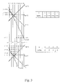
- FIG. 7 is a diagram of a Parity Edge Decoder.
- FIG. 8 is a diagram of a Syndrome Edge Decoder.
- FIGS. 9A-B are diagrams of a data array that illustrate a decoding example.
- FIGS. 10A-C are diagrams of a data array that illustrate a decoding example.
- FIGS. 11A-B are diagrams of a data array that illustrate syndrome calculation.
- FIG. 12 is a block diagram of a decoder.
- FIG. 13 is a diagram of an encoded array.
- FIG. 14 is a diagram of a data array that illustrates a decoding example.
- FIGS. 15A-D are diagrams of a data array that illustrate a decoding example.
- FIGS. 16A-C are diagrams of a data array that illustrate a decoding example.
- FIG. 17 is a diagram of an encoded array.
- FIG. 18 is a diagram of a data array that illustrates a decoding example.
- FIG. 19 is a diagram of an encoded array.
- FIG. 20 is a block diagram of an implementation of a storage system.
- FIG. 21 is a diagram of a storage device.
- FIG. 22 is a block diagram of an implementation of a storage system.
- FIG. 23A is a diagram of a data array that illustrates a decoding example.
- FIG. 23B is a diagram of a data array that illustrates a decoding example.
- a distributed transmission and/or storage system 100 accepts source data 110 , which is represented by the system as a finite length block of N parallel data channels (also referred as “fields”), each channel including a series of entries (or “items”).
- source data 110 is represented by the system as a finite length block of N parallel data channels (also referred as “fields”), each channel including a series of entries (or “items”).
- the data may be naturally divided into parallel data channels, or alternatively, the system 100 may segment the data into separate channels as part of its input processing.
- the data may represent audio/video recordings, which are stored by the system 100 for later transmission on demand to viewers serviced by the system.
- the system can segment a continuous stream into blocks.
- Kb 64 kilo-bits
- a data encoder 115 of the system accepts the N parallel data channels of source data 110 and computes an additional M channels of redundant data that is generally based on parity computations on the source data.
- the (N+M) parity encoded channels 120 are stored in a distributed storage system 125 , for example based on magnetic disk storage devices.
- the separate storage devices may be implemented using separate computers on a data network, and the separate computers can be geographically distributed for added resilience against errors that are caused by geographically-localized phenomena (e.g., earthquakes).
- the (N+M) channels are transmitted from the encoder 110 to the decoder 135 without storage (other than buffering in the transmission system).
- Errors may be introduced in the data at a number of different points. For example, data errors may be introduced during transmission of data from the data encoder 115 to the storage devices 126 . Once stored, data may be introduced within the storage devices themselves, for example, due to media faults in the devices or due to failures of entire devices. For example, with sufficiently large quantities of stored data, even with today's high data reliability rates, at least some errors are likely be introduced while that data is stored. Finally, data transmission errors may be introduced when the data is retrieved from the storage devices 126 .
- erasures are different then corruptions in that an erasure of a channel can be distinguished from incorrect data on that channel by a downstream decoder without having to apply an error detection algorithm, for example using multiple channels.
- erasures can be indicated by side information (not illustrated) that indicates the status of a channel or a range of data within a channel.
- the system 100 includes a data decoder/repairer 135 , which receives the N+M 130 channels that may have errors from storage system 125 , or alternatively directly (e.g., over imperfect transmission channels) from the data encoding module 115 if the data is not stored.
- This module serves functions including detection of errors in particular channels of the stored data, and based on the detected errors both reconstructs error-free data 140 for transmission to users of the data and optionally passes rebuilding data 145 for correcting errors that may be represented in the stored data to the distributed data 125 .
- the rebuilding data 145 is used to correct those errors so that if the same data is later read from the storage 125 , it will no longer be in error.
- the error-free data 140 can include all (N+M) channels (i.e., including the redundant channels), or alternatively only the original N channels are provided. Providing all (N+M) enables downstream application of further decoding and repair modules 135 , for example to correct errors made during the downstream transmission or in subsequent storage of the channels.
- the data encoder 115 and the corresponding data decoder/repairer 135 implement an encoding/decoding procedure that is generally applicable in situations in which source data 110 can be represented as a source array D 112 .
- an entry D ni represents a data value at row i column n (i.e., channel n), where the row indices range from 0 to I ⁇ 1 and the column indices range from 1 to N.
- the data values D ni are treated as binary digits but multibit values can be handled as well, for example, by processing each bit position separately or performing logical operations on an entire multibit word in parallel (i.e., FIG. 1B represents one bit of the multibit data).
- the encoded data 120 is represented by a somewhat larger encoded array 122 .
- the encoded array has M additional columns of redundant (“parity”) data, with column indices for the redundant data ranging from ⁇ M+1 (the “leftmost”) to 0 (the “rightmost”) with entries P mi , where ⁇ M ⁇ m ⁇ 0. Therefore, the column indices of the encoded array 112 range from ⁇ M+1 to N.
- the encoded array 122 includes a number of additional rows at row indices less than 0 and greater than or equal to I.
- the values in the additional rows are defined to have zero entries (or alternatively are defined to have a pattern of values that will be known to the decoder without error).
- parity columns i.e., columns ⁇ M+1 through 0
- parity data in general extends for a number of rows before row 0, and for a number of rows after row I ⁇ 1.
- firstbit n is the first (lowest index) row that may have nonzero data in column n
- lastbit n is the row index of the last row that may have nonzero data in column n.
- the repaired data 140 can be represented as a repaired array 142 , which has the same structure as the source array 112 .
- the encoding approach is applicable to situations in which errors are likely to remain within a limited number of columns. For example, this can be the case when each column is associated with a particular storage device, a communications channel, or a communications packet. In such situations, many errors might be expected to occur in the columns associated with those devices with no errors in other devices.
- the data encoder produces a set of parity columns whose values are generated from a set of parity equations.
- Each parity equation forms a constraint on the entries to which it is applied (i.e., on the entries that appear in the equation, which are also referred to as the arguments of the parity equation).
- the encoding in these versions can be accomplished using various selections of bits for each parity equation.
- a preferred way to select bits for the parity equations is to select the bits is to establish straight lines across the data columns, with each parity equation using a line at a different slope.
- the parity equation for a line is the sum (modulo 2, or equivalently an XOR) of the values in the array that intersect the line.
- parity equations for successive parity values in a particular parity column therefore correspond to parallel lines through the data and parity columns. Every data value (bit) is contained in one and only one of the parity equations for any particular parity column. That is, in general each data value is intersected by multiple parity equation lines, but at most one line associated with a particular parity column. Parity equations are independent. Therefore no two parity equations share (i.e., have lines that cross at) any more than one data or parity bit.
- one general decoding method is to work from bottom to top, calculating each unknown data bit in a column, one at a time, from lower row index, known good or corrected bits in the same column, and known good or corrected bits from other columns, using the relationships established by the multiple, crisscrossing equations.
- This “cross-convolution” differs from other convolution approaches in that data column bits are not just generated from the column's own earlier values, but also from values in other columns.
- a mapping pcolL m to be the column index in which parity value m is stored
- its inverse mapping lpcol n to be the index of the parity value that is stored in column n.
- definitions of pcolL m and lpcol n are provided in EQS. 1.1-1.2.
- Each parity value in a row is associated with a line of a particular different slope.
- the rightmost parity uses the highest slope line, and the leftmost parity uses the lowest slope line.
- the quantity K m denotes the slope of a line 210 , denoted L m , associated with parity index m.
- firstbit n and lastbit n are defined in PROC. 1.1.
- line slopes K m ⁇ 2, . . . , +1
- the values of firstbit n are ⁇ 2, ⁇ 4, ⁇ 5, ⁇ 5
- the values of lastbit n are I+13, I+11, I+10, I+10, respectively.
- different line slopes for example ascending with increasing column index, result in different values of firstbit n and lastbit n for the parity columns.
- firstbit 1 is ⁇ 5 so that a line of slope 0 from P ⁇ 1, ⁇ 5 passes through P 0, ⁇ 5 .
- firstbit 2 is ⁇ 4 so that a line slope of ⁇ 1 from P ⁇ 2, ⁇ 4 passes through P ⁇ 1, ⁇ 5 .
- firstbit 3 is ⁇ 2 so that a line of slope ⁇ 2 from P ⁇ 3, ⁇ 2 passes through P ⁇ 2, ⁇ 4 .
- the lastbits are determined similarly.
- a set of exemplary parity lines 210 are illustrated, with the parity value associated with a line being indicated by a filled square and a data or parity value used to compute the parity value being indicated by a filled circle.
- the parity value P ⁇ 2,i+5 is computed using parity values P ⁇ 3,i+6 , P ⁇ 1,i+4 , P 0,i+3 , D 1,i+2 , D 2,i+1 , D 3,i , D 4,i ⁇ 1 , and D 5,i ⁇ 2 .
- the sum (modulo 2, or equivalently the logical XOR) of all values indicated along each line is zero. Note that each data value has M lines at different slopes passing through it and therefore is part of M separate (and linearly independent) parity equations.
- PROC. 1.2 cannot be directly implemented as shown because some of the values on the right hand side of EQ. 1.3 have not yet been computed when a particular parity value in the iteration is to be computed. Therefore, PROC. 1.2 should be treated as “conceptual,” with a specific encoding method that can be implemented being presented later in this description.
- each parity line does not necessarily make use of all the parity values (i.e., only a subset of array entries intersecting a line are part of the associated parity equation), while each data value remains part of M separate parity equations.
- a first type of decoder addresses a situation in which M columns of an encoded array 122 are erased. That is, the decoder is given the column indices e 0 ⁇ e 1 ⁇ e M ⁇ 1 that need to be rebuilt and all the data in the remaining columns are assumed to be uncorrupted (“good”).
- an aspect of this approach is the use of a series of equations which are “tangents” to a curve that separates the data and parity space into two areas: below the curve are known good, assumed zero, or rebuilt bits, and above the curve are known good or erased bits. As each equation is applied, it includes one erased bit and one known good or already rebuilt bit along the curve, and other bits which are below the curve and therefore also known good or rebuilt.
- the approach begins with rebuilding of the parity value P 0, ⁇ 5 410 based on a parity line L 3 of slope +1 passing through the known data value D 5,0 and other assumed zero values. Then P ⁇ 1, ⁇ 5 411 is rebuilt using L 2 of slope 0 passing through the rebuilt P 0, ⁇ 5 value. Then P ⁇ 2, ⁇ 4 412 is rebuilt using line L 1 of slope ⁇ 1, and finally P ⁇ 3, ⁇ 2 413 is rebuilt using a line L 0 of slope ⁇ 2. In each case, the parity bit being rebuilt is the only unknown value on the parity line allowing it to be determined from the corresponding parity equation.
- the approach continues with a next iteration of rebuilding one value from each of the erased columns with rebuilding P 0, ⁇ 4 420 , which is based on two data values D 4,0 and D 5,1 as well as the rebuilt parity value P ⁇ 1, ⁇ 5 . Then values P ⁇ 1, ⁇ 4 421 , P ⁇ 2, ⁇ 3 422 , and P ⁇ 3, ⁇ 1 423 are rebuilt in turn.
- the iterations are continued until the last iteration in which the lastbit of each parity column is rebuilt.
- e 0 . . . e (M ⁇ 1) 2, 3, 4, and 5. That is, the rightmost 4 data columns are erased.
- lines L 0 through L 3 are used to rebuild values in columns D 2 through D 5 , respectively.
- D 2,0 510 is rebuilt using known values in columns P ⁇ 3 through D 1 .
- D 3, ⁇ 1 511 is rebuilt using the newly rebuilt value of D 2,0 .
- D 4, ⁇ 1 512 is rebuilt and finally D 5,0 513 is rebuilt.
- the next bit position in each column is computed in the same column order. Note that D 3, ⁇ 1 511 at the first iteration is known to be zero, so this initial re building is redundant, as is the rebuilding of D 4, ⁇ 1 512 .
- FIG. 6 shows an iteration which is rebuilding at some middle row of the data.
- the P ⁇ 2 column is the leftmost good column, with one erased column to the left, so P ⁇ 3 is rebuilt first, using L 0 ; P 0 , D 1 , and D 4 are then rebuilt, in that order, using lines L 1 to L 3 , respectively. In all cases, only one bit along the line is erased, the others are either given, known good, or already rebuilt.
- PROC. 2.2 is used to determine the firstbit for a number of the columns. For the parity columns, firstbit n is computed as in PROC. 1.1.
- the firstbit 1 value for the first data column D 1 may also be needed, and is defined based on the firstbit 0 value for the rightmost parity column and the slope K M ⁇ 1 of the most positive line L M ⁇ 1 .
- K 3 +1
- firstbit 0 ⁇ 5
- firstbit 1 ⁇ 4.
- PROC. 2.3 defines the starting point for the iteration.
- the first bit of the leftmost good column defines this starting point.
- the starting rows for each of the erased columns e m are defined by this firstbit and the slopes of the parity lines in PROC. 2.4.
- PROC. 2.4 erased columns to the left of the leftmost good column are handled separately from those on the right because the order of rebuilding is “outward” from the leftmost good column.
- the erased columns are the four rightmost data columns.
- the first rebuilt bits of the remaining columns are D 4, ⁇ 13 and D 5, ⁇ 12 . Note that these starting rows are somewhat conservative because a first number of iterations “rebuilds” assumed zero entities, and it is not until the iteration shown in FIG. 5 that the first real data is reconstructed.
- PROC. 2.5 represents the rebuilding loop.
- the variables P, D, and PD refer to the original uncorrupted quantities in the good columns and the incorrect or erased (taken to have value zero) and not yet rebuilt values in the remaining columns.
- the variable X refers to a rebuilt value and is defined only for the columns being rebuilt, and the variable XPD refers to the rebuilt value X or the original good value PD depending on the column.
- each iteration updates the M erased columns.
- the procedure implements EQ. 2.5, which corresponds to the parity equation used to rebuild one entry. The iterations are continued until the lastbit of each of the erased columns are rebuilt.
- Implementations of the Parity Edge Decoder described in the previous section can require a memory window buffer for columns of the parity and data, where the window width W is equal to the number of rows needed for the steepest equation across all columns. This is at least 1 ⁇ (N+M), and is typically (M/2) ⁇ (M+N).
- the buffer stores all of the data and parity bits (M+N) in the window, so the total storage is (M+N) ⁇ W, or typically (M/2) ⁇ (M+N) ⁇ (M+N) bits to hold all of the good and rebuilt data and parities.
- a parity edge decoder 730 make use of a window buffer 710 that provides W delayed samples 720 of N+M good or rebuilt values to the decoder.
- the good parities can be precalculated by generating “enhanced syndromes,” which are conventional syndromes with the bad (erased) columns removed (i.e., not included in the parity sum).
- enhanced syndromes By precalculating and storing the enhanced syndromes, only M syndrome bits and the M rebuilt bits are stored across the window, so the storage requirement is reduced to 2 ⁇ M ⁇ W.
- the conventional syndrome is defined as the right hand side of equation EQ 1.3 XOR'd with the left hand side (the parity result). This results in a syndrome value of 0 when all parity and data bits are correct.
- the location of the syndrome bit for a particular parity equation is arbitrarily defined to be at the row and column indexes of the parity value for the corresponding parity line.
- the conventional syndrome bits S pcolL m,i are computed in a similar iteration as used to compute the parity values during encoding.
- an enhanced syndrome, ES is computed as is the conventional syndrome with the erased columns removed; i.e., it does not include columns e 0 ⁇ e 1 ⁇ . . . e (M ⁇ 1) .
- N good columns are passed through a shift XOR module 805 which outputs a stream of M enhanced syndromes per time step.
- the enhanced syndromes are buffered in a window buffer 810 , which passes W delayed versions of M enhanced syndromes to the syndrome edge decoder 830 .
- the decoder rebuilds the erased columns they are passed to a rebuilt data buffer 860 , from which the syndrome edge decoder 830 retrieves the rebuilt data as needed.
- the syndrome edge decoder uses essentially the same procedure as parity edge decoder, but uses the enhanced syndromes in place of the good columns as shown in PROC. 3.3.
- the Parity Edge Decoder and Syndrome Edge Decoders described above rebuild one bit from each bad column before moving on to a next iteration step to rebuild the next bit in each column.
- a Parity Error Canceling Decoder can ignore all but one of the bad columns while rebuilding the remaining bad column, thereby enabling possible parallel implementations in which different erased columns are rebuilt in parallel.
- a general approach for handling any value of M is also presented below.
- Parity Error Canceling Decoder approach combines a particular set of parity equations to create crossing points on the columns to be ignored, such that at each of the crossing points an even number of lines intersect. This results in the bit from those intersecting positions are XOR'd twice (or a multiple of two times) into the result, which cancels it.
- the parity equations cross the column to be rebuilt in more than one place; the highest (latest) crossing point is rebuilt in terms of the lower (earlier) ones, which were rebuilt on previous passes of the iteration.
- the iteration starts on the firstbit of the column to be rebuilt, so that all previous bits are given, and finish when we have rebuilt the lastbit of the column.
- the geometry can be warped in many ways as long as the slope of L 1 equals the average slope of L 0 and L 2 .
- a value D 3,i 930 is rebuilt by adding the two parity equations on lines L 0 940 and L 1 942 such that P 0,i ⁇ 3 932 is cancelled.
- each erased column P 0 and D 3 can be rebuilt independently, for example in parallel.
- FIGS. 10A-C the approach illustrated in FIGS. 9A-B is extended to forming linear combinations of three parity equations in order to cancel values in two of three erased columns at a time.
- columns P ⁇ 2 , D 1 , and D 2 are erased and have to be rebuilt.
- L 0 920 in order to rebuild P ⁇ 2,i 910 , three parity lines are combined: L 0 920 , L 1 922 , L 1 923 (i.e., a second line L 1 with a different row offset), and L 2 924 .
- This combination of parity lines results in canceling the terms on those parity lines in erased columns D 1 and D 2 . That is, the data values D 1,i ⁇ 3 , D 2,i ⁇ 3 , D 1,i ⁇ 4 , D 2,i ⁇ 4 , are all cancelled out when rebuilding P ⁇ 2,i 910 .
- D 1,i 930 is rebuilt with lines L 0 940 , L 1 942 , L 1 943 , and L 2 944 , thereby canceling the entries on the parity lines in columns P ⁇ 2 and D 2 .
- entry D 2,i 950 is similarly rebuilt using lines L 0 960 , L 1 962 , L 1 963 , and L 2 964 .
- P ⁇ 2,i three previously rebuilt values in column P ⁇ 2 are used: P ⁇ 2,i ⁇ 3 , P ⁇ 2,i ⁇ 4 , and P ⁇ 2,i ⁇ 7 .
- the base row index (also referred to as the “base offset”) of a line L is defined as the row index of the parity bit calculated along line L.
- the base offset of a line is found by calculating the offsets from the error point along lines; then moving to the base of a line, then to the crossing point of that line with the next line, then to the base of that next line, then to another crossing point, etc., until the base of the desired line is found.
- syndrome S pcolL m,i contains all of the points along the line L m with slope k m , and containing point P pcolL m,i (the base of the line) as defined in EQ. 3.1:
- the columns being cancelled 2312 are offset from the leftmost column by a, b, and c columns (i.e., columns PD a ⁇ M , PD b ⁇ M and PD c ⁇ M according to the previously introduced notation), while the column 2310 being reconstructed is offset by d columns (i.e., PD d ⁇ M ).
- an entry 2320 is reconstructed based on parity equations, each of which includes each of the M columns that are being cancelled or reconstructed.
- a line L 3 is first chosen to pass though the entry 2320 to be reconstructed. Then a line L 2 is chosen to cancel the entry in the column at offset c. Lines are successively chosen to implement the cancellation until all entries in the columns at offsets a-c are cancelled.
- a basis for combinations of parity equations that cancel particular subsets of columns can be determined based on matrix algebraic techniques (over the field of numbers modulo 2) to identify the sets of parity equations that sum to zero (modulo 2) in the selected columns.
- the selection of parity equations for particular subsets of columns to cancel can be precomputed and stored in the system, so that an appropriate combination of parity equations can be selected based on the columns that need to be cancelled without requiring computation to determine the combination at runtime.
- the Parity Error Canceling Decoder can be implemented using a buffer of (N+M) times the window width to hold all of the good and rebuilt data and parities. Since new bits are calculated using earlier bits, the syndromes must be recalculated as each new bit is calculated. Like the Syndrome Edge Decoder, a more efficient method, the Syndrome Error Canceling Decoder, can be implemented using syndromes. There are several differences, however. Since we will eventually cancel the bad columns, we can use conventional syndromes (defined by EQ. 3.1) which include all of the data columns, and don't have to calculate special enhanced syndromes based on the error columns.
- FIG. 12 An example implementation for the X e0 output (EQ. 5.3) of a syndrome canceling decoder is shown in FIG. 12 .
- the boxes are shift registers, which create a delay (or negative offset) for each register bit.
- the three syndrome fields 1220 , 1222 , and 1224 and the actual value of the PD e0 field 1210 are inputs, but are delayed in the shift registers before being XOR'd together in block 1260 .
- the corrected output X e0 is fed back again through shift registers to be XOR'd also.
- the delta values are set to the negative of the predecessor value, to create a positive delay, and thus the originally intended negative offset.
- the base values are often negative offsets, but can be positive. Since a shift register cannot have a negative number of bits, a window size W is added to each syndrome shift register. To keep everything even, we have to add that same delay to all of the input shift registers.
- the window size W is used since the base of a line can be W ahead of the X e0 bit at most. An option is to reduce this window, since the base in actuality will not quite get as far as W ahead of any X e0 .
- the decoding methods described above generally use the fully cross-convolved encoding as defined in EQ. 1.3. That is, all of the data and other parity bits along a parity line are included in the parity bit for that line. Therefore while up to M data columns can be rebuilt, all N+M data rows are read to rebuild any number of columns, even in the typical case where only one column is erased. The choice of value for M must be made before any parity bits are calculated, since all parity bits are included in all other parity bits' equations.
- Partial Cross-Convolutional Encoding allows limited reading of parity columns (the same number of parity columns as there are erased columns to be rebuilt), and which allows incremental addition of parity columns without re-encoding previous ones.
- parity values are define in PROC 6.0, in which EQ. 6.1 replaces EQ. 1.3 in PROC 1.2.
- each parity value makes use of the parity column directly to its right (if any) and does not use the other parity columns.
- P ⁇ 3 makes use of P ⁇ 2 but not P ⁇ 1 or P 0 .
- Parity column P 0 which has no parity column to the right, only includes data columns.
- any parity P n can be generated from data and parity P n+1 (if there is one), without regard to any other parities, in particular, without regard to any parity to the left.) This allows parities to be added one at a time (leftward) using only previous parities, and allowing decoding to take place using only as many parities as are needed for the number of erased columns to rebuild.
- Encoding according to this approach follows PROC. 1.2, with equation EQ. 1.3 replaced with EQ. 6.1. Since parity lines do not contain all parity bits, the parity edge decoder and enhanced syndrome edge decoder procedures are modified accordingly.
- the firstbit and lastbit calculations remain the same, as in the previous approaches because the omitted parity bits are outside of valid bits defined in the previous approaches.
- FIG. 14 which corresponds generally to FIG. 6 , columns P ⁇ 3 , P 0 , D 1 , and D 5 are erased.
- Column P ⁇ 2 is the leftmost good column, therefore the only erased column to its left is P ⁇ 3 .
- the starting bit is therefore at P ⁇ 2,i 1405 .
- the first reconstructed bit is therefore P ⁇ 3,i+2 1410 using line L 0 of slope k 0 .
- the line L 2 of slope zero is applied. By construction, it can be shown that this line will intersect at most one as-yet not rebuilt entry of the erased column, but this column may be to the left rather than to the right. In this case, entry P 0,i ⁇ 3 1430 is such an entry that is next rebuilt.
- the procedure starts again at D 1,i ⁇ 3 1420 , which is used to rebuild D 4,i 1440 using line L 3 of slope +1.
- PROC. 6.5 is used.
- PROC 6.6 is used.
- FIGS. 15A-B consider first a situation in which P 0 and D 3 are erased. These figures should be contrasted with FIGS. 9A-B in which full parity equations are used to cancel columns.
- FIG. 15A when P 0,i 1510 is rebuilt, lines L 0 1520 and L 1 1522 are used to cancel D 3 ,i 1512 .
- line L 1 1522 differs from line L 1 922 in FIG. 9A in that P ⁇ 1,i ⁇ 4 1524 is not part of the parity equation for line L 1 1522 while it is for line L 1 922 .
- the rebuilding procedure is used without modification.
- FIG. 15B when D 3,i 1530 is rebuilt, lines L 0 1540 and L 1 1542 are used to cancel P 0,i ⁇ 3 1532 , with line L 1 1542 not including entry P ⁇ 1,i ⁇ 4 1544 .
- parity line L 0 includes P ⁇ 2 and P ⁇ 1
- line L 1 includes P ⁇ 1 and P 0
- line L 2 includes P 0 alone.
- FIGS. 16A-C which should be compared to FIGS. 10A-C , columns P ⁇ 2 , D 1 and D 2 are erased.
- P ⁇ 2,i 1610 is rebuilt, with four lines canceling the other erased columns: L 0 0 1620 , L 1L 0 1622 , L 1H 0 1623 , and L 2 0 1624 .
- L 0 0 1620 L 1L 0 1622
- L 1H 0 1623 L 1H 0 1623
- L 2 0 1624 This situation is analogous to that illustrated in FIG. 10A .
- FIG. 16B when D 1,i 1630 is rebuilt, line L 1 1 1642 is used, but unlike line L 1H 1 943 in FIG. 10B , erased entry P ⁇ 2 ,i is not included and therefore does not have to be cancelled.
- Line L 2 1 1644 is used to cancel D 2,i , but that line also does not include erased parity P ⁇ 2 . Therefore, only two parity equations rather than four are required to rebuild D 1,i . Referring to FIG. 16C , the situation is similar with only two lines, L 1 2 1662 and L 2 2 1664 being needed to reconstruct D 2,i 1650 .
- a general procedure for determining which lines to include in reconstructing a column is provided in PROC. 6.9.
- the lines for the parity equations do not necessarily have to be straight across all the columns of the parity and data.
- a possible advantage of using other than straight lines is the fewer extra bits may be needed beyond the first and last rows of the original data.
- a particular variant of the Partial Cross-Convolutional Encoding method sets the slope of the parity equation line to zero from parity column P 0 leftward; thus there is a bend in the line at parity column P 0 , unless the whole line is horizontal.
- the leftmostgoodbit is found in column P ⁇ 2 .
- P ⁇ 3,i 1810 is first rebuilt using line L 0 , which uses P ⁇ 2,i but not P ⁇ 1,i or P 0,i .
- D 1,i ⁇ 1 1820 is rebuilt using P ⁇ 2,i and P ⁇ 1,i .
- P 0,i ⁇ 1 1830 is rebuilt using L 2 , which uses the rebuilt D 1,i ⁇ 1 1820 .
- D 4,i+2 1840 is rebuilt using the rebuilt D 1,i ⁇ 1 and P 0,i ⁇ 2 .
- a procedure for determining the firstbits and lastbits for the parity columns, as well as modifications of the procedures and equations for the parity and syndrome edge decoders are PROC. 7.1.
- the slopes of the “flat parity” lines can be chosen such that line L 3 1910 has zero slope, and the remaining lines have negative slope as shown in the figure.
- P 0 in this example corresponds to a simple parity along one data row, as may be used in a RAID storage system. For example, an erasure of a single data column could be handled using P 0 alone, for example, using components of the RAID storage system.
- the additional parity columns, P ⁇ 3 through P ⁇ 1 provide the capability of reconstructing up to four concurrent erasures should they occur.
- a modified method calculates higher order parity columns ( ⁇ 1 to ⁇ (M ⁇ 1)) using line slopes in a re-arranged order (not k M ⁇ 2 to k 0 ).
- the effect of this method is to simplify calculations in the parity and syndrome error cancellation decoding methods, since slopes are either +1, ⁇ 1, or 0, changing multiplication of offsets by slopes into addition, subtraction, or disregard of offsets.
- slopes of alternating signs (0, +1, ⁇ 1, +2, ⁇ 2, . . . ) are used in conjunction with a version of the approach in which parity columns are added both to the left and to the right of the data columns, and successive parity equations make use of successively more of the parity columns.
- Some other choices of non-sequential slopes may disrupt the “spline curve” during reconstruction, such that erased extra parity bits at i ⁇ 0 are used to rebuild data bits before the parity bits themselves have been rebuilt.
- the extra parity bits are stored in an externally reliable mechanism so they are always available, even if the parity column is erased.
- data bits for rows before row 0 are defined to be known zero values, thereby allowing diagonal parity equations to be calculated when only some of the entries in the parity equation are at row 0 or later.
- these known entries are defined in encoding to have a pattern of values that is not necessarily all zero. This pattern of values serves as a scrambling key that is needed by the decoder in order to start the decoding process. That is, if the encoder uses a pattern of non-zero values, and M data columns are erased before sending the data from the encoder, then the decoder will not produce correct output if it uses zeros or an incorrect pattern of values to rebuild the missing M data columns. These extra data bits can be handled separately, and treated as a key that is needed to decode the data.
- Parity equations do not necessarily use all the data columns as arguments.
- a hierarchical approach may be used.
- a third parity uses all columns D 1 through D 16 .
- This approach can be extended to more hierarchical levels, with higher level parities covering progressively more columns.
- the parities covering the lowest level are implemented using a RAID approach, and the higher-level parities are used to recover multiple errors in a RAID bank that are not recoverable using RAID alone.
- One approach to detection of columns with errors involves computing syndromes in which different subsets of 1 up to m columns, for m less than the number of parity columns M, are cancelled using the approaches described above for syndrome-cancellation based decoding. If without cancellation the syndromes are non-zero, and with cancellation of a particular subset they are zero, then the cancelled columns are assumed to have errors and are rebuilt completely.
- An implementation of this approach makes two (or more) passes through the computed syndromes if they are not all zero. For example, a first pass through the data may examine the syndromes to determine whether there are any non-zero values, which indicate that there is some error. The cancellation of columns can then be performed iteratively, for example, first canceling one column at a time, then canceling pairs of columns at a time, and so forth until, in the rare situation in which there truly are M ⁇ 1 columns with errors, combinations of M ⁇ 1 columns are cancelled.
- a single pass through the data in which all the various subsets of column cancellations are computed together is used to identify the subset of columns that is to be treated as erased and then rebuilt.
- a single streaming pass is used to both detect the subset of columns to reconstruct and with a suitable delay reconstruct the columns in error.
- the single-pass error detection logic can mark that column as “erased” for a lagging decoder to reconstruct.
- a hash code or message digest (e.g., MD5) can be calculated and appended to each channel, and if the hash code or message digest does not match when recomputed at the decoder, the decoder treats the channel as “erased.”
- a syndrome-based decoder/repairer 135 accepts data from a distributed storage 125 , which includes multiple separate storages 126 , each associated with a different channel (column) of data.
- the N+M channels of data are passed from the storage 125 to a streaming repairer 2035 .
- the data is also passed to a syndrome calculator 2010 , which provides syndromes 2015 to the streaming repairer 2035 .
- the streaming repairer 2035 uses parameters 2030 that define which columns to rebuild. It uses these columns to configure a streaming reconstruction component. For example, the streaming repairer implements one or more configurable delay lines and summers of a type shown in FIG. 12 .
- the configuration information determines the amount of delay in each of the delay lines 1230 - 1243 , and the selection of inputs to the delay lines.
- a corruption detector 2020 also makes use of the syndromes 2015 to determine which columns need to be rebuilt, and passes this information to the streaming repairer 2035 .
- the corruption detector 2020 may also make use of other information 2025 , for example, from the distributed storage 125 that identifies columns that need to be rebuilt. For example, if the corruption detector 2020 is informed or determined that a particular storage 126 is unavailable, it can identify that column as erased in addition to other columns in which errors are detected based on the syndrome calculations.
- each storage 126 may include a error detection capability, based for example on a parity or ECC, and if it detects one or more errors, for example, in a requested block of I rows of data, it sends that information in such a way that the corruption detector and/or the streaming repairer can use to information to reconstruct the data.
- a error detection capability based for example on a parity or ECC
- the decoder repairer 135 may include sufficient storage to buffer the required data.
- the data may be read multiple times from, and reconstructed data sent back to, the distributed storage 125 .
- the approaches described above may be implemented in software, which is stored on computer readable media or distributed on signals, for example, propagating in a data network.
- the software can include instructions (e.g., computer processor instructions, processor microcode, virtual machine instructions, interpreter statements or byte codes, etc.), that cause various of the system components described above to perform the functions described.
- the approaches may also be implemented in hardware, for example, using special purpose circuitry, programmable logic, programmed processors and controllers.
- the approaches may also be implemented using combinations of software and hardware.
- each storage may be implemented using a variety of types of devices, include multi-computer systems (e.g., disk server “farms”), general purpose computers (e.g., “disk servers”), special purpose storage subsystems, disk drives, portions (e.g., platters) of individual disk drives.
- the data interconnection can use a variety of data network or communication technologies, for example, including Internet Protocol (IP) communication, ATM, Ethernet, Fiberchannel, SCSI, ATA, etc.
- IP Internet Protocol
- a first application of the approaches described above is in distributed storage.
- Each channel is stored separately (i.e., in a storage 126 ), in a manner that reduces the correlation of errors between different channels.
- the channel may be geographically or spatially distributed at some level (e.g., at data centers different continents, in different countries, in a different city, in a different building, in a different computer room, in a separate rack, in a separate chassis in a rack, on a separate board or blade in a chassis).
- N separate channels if not already naturally divided
- an encoder computes the additional parity values for storage.
- each storage 126 may have some error correction and detection capability.
- each storage 126 may itself include a RAID disk system that is able to correct at least some errors, for example, if it detects that a drive in the array is bad.
- the data is protected by a parity, which is used when the RAID system detects that a disk is not available. This same parity can be used to detect the presence of an error that cannot necessarily be repaired by the RAID system.
- the storage 126 informs the decoder repairer that its data is corrupted, optionally indicating the range of rows in a block of I rows in which the error appears.
- the individual storages 126 continually read their data and use their own internal error detection capabilities to detect errors, and if errors are detected but cannot be independently repaired by the storage 126 , data at other of the storages 126 is used to reconstruct the data.
- each or at least some of the storages 126 include the decoder repairer functionality, and therefore such a storage can request the data it needs from the other storages to reconstruct its errorful data.
- a storage that detects an error can request a remote decoder repairer to reconstruct its data.
- each channel is associated with a different disk storage device.
- a representative channel of a block may be stored in a representative disk block that includes a section 2110 that stores 512 Kb as well as a section 2115 that stores any required extra bits (i.e., before row 0 and after row I ⁇ 1) for that channel.
- a particular application of this approach makes use of a very large number of relatively error-prone but inexpensive disk drives.
- Such disk drives might have inadequate error rates on their own, but in combination with a subsystem controller that implements the encoding to distribute parity channels to various drives, and a decoder repairer to detect and correct errors, very low overall error rates are achieved at relatively low cost.
- error detection is performed in a streaming manner that does not substantially delay reading of data. When an error is detected, the data is read and reconstructed using the parity data.
- each disk may have its own error detection and/or error correction capability, and when an error is detected but not correctable by the drive, it can inform the subsystem controller of the error and the subsystem controller rebuilds the data, if necessary, migrating the data to another drive if the drive is no longer functional.
- semiconductor memory e.g., RAM
- N+M banks of memory 2210 each coupled to a memory controller 2220 .
- the memory controller includes an encoder that computes the parity channels and a decoder repairer for rebuilding banks that have errors or become unavailable.
- each memory bank may include error detection and/or error correction capabilities, and may be able to provide error detection information, for example, localizing errors, so that the memory control can rebuild the errorful data.
- memory modules have 72-bit wide data storage. Other systems can use these 72 bits for 64 bits of data and 8 bits for ECC for correction within the module.
- the 8 bits are used for 8 parity channels that are used for correction across memory modules, enabling for example, reconstruction of up to 8 erased bit positions across the memory modules.
- the separate channels of a block of data are each passed over separate data communication channels, or are passed over a same communication channel but at sufficiently different times or in different data packets such that errors in different of the columns of data are substantially uncorrelated.
- each channel may be send over a different physical circuit (conductor or optical fiber), or a different frequency such that different frequencies are subject to relatively independent interference.
- Each channel may also be packaged into a separate packet for transmission over a packet-switched data network, and routed over the same or different paths through the network.
- a software implementation of the approach is used to protect portions of a computer file system.
- the separate channels can correspond to different units of file storage, such as blocks or other segments of a file, separate files, separate directories, or other partitions of a file system.
Landscapes
- Engineering & Computer Science (AREA)
- Theoretical Computer Science (AREA)
- Physics & Mathematics (AREA)
- Probability & Statistics with Applications (AREA)
- Computer Networks & Wireless Communication (AREA)
- Signal Processing (AREA)
- Quality & Reliability (AREA)
- General Engineering & Computer Science (AREA)
- General Physics & Mathematics (AREA)
- Error Detection And Correction (AREA)
- Detection And Correction Of Errors (AREA)
Abstract
Description
-
- Select the leftmost good column.
- Starting at the leftmost good column, rebuild one bit of each of the erased columns moving outward (to left and to right from the leftmost good column), using lines in order such that L0 is used for leftmost erased column and L(M−1) is used for rightmost erased column. The first bit position in the column to be rebuilt is based on the firstbits of the good columns.
- If the leftmost parity column is good, start on the firstbit of that column and therefore L0 will go from there to the leftmost erased column.
- If the leftmost parity column is erased, and the leftmost good column is a parity column, start on the firstbit of the leftmost good column.
- Otherwise, all of the parities are erased, and the leftmost good column is D1 and therefore start on D1 at the point where L(M−1) crosses D1 and the firstbit of P0.
- Increment all bit numbers and repeat until all erased columns have had their respective lastbit rebuilt.
Claims (49)
Priority Applications (2)
| Application Number | Priority Date | Filing Date | Title |
|---|---|---|---|
| US11/187,737 US7716566B2 (en) | 2004-07-22 | 2005-07-22 | Data error control |
| US12/728,832 US7882425B2 (en) | 2004-07-22 | 2010-03-22 | Data error control |
Applications Claiming Priority (2)
| Application Number | Priority Date | Filing Date | Title |
|---|---|---|---|
| US59030704P | 2004-07-22 | 2004-07-22 | |
| US11/187,737 US7716566B2 (en) | 2004-07-22 | 2005-07-22 | Data error control |
Related Child Applications (1)
| Application Number | Title | Priority Date | Filing Date |
|---|---|---|---|
| US12/728,832 Division US7882425B2 (en) | 2004-07-22 | 2010-03-22 | Data error control |
Publications (2)
| Publication Number | Publication Date |
|---|---|
| US20060156178A1 US20060156178A1 (en) | 2006-07-13 |
| US7716566B2 true US7716566B2 (en) | 2010-05-11 |
Family
ID=35786766
Family Applications (2)
| Application Number | Title | Priority Date | Filing Date |
|---|---|---|---|
| US11/187,737 Active 2028-05-02 US7716566B2 (en) | 2004-07-22 | 2005-07-22 | Data error control |
| US12/728,832 Expired - Lifetime US7882425B2 (en) | 2004-07-22 | 2010-03-22 | Data error control |
Family Applications After (1)
| Application Number | Title | Priority Date | Filing Date |
|---|---|---|---|
| US12/728,832 Expired - Lifetime US7882425B2 (en) | 2004-07-22 | 2010-03-22 | Data error control |
Country Status (2)
| Country | Link |
|---|---|
| US (2) | US7716566B2 (en) |
| WO (1) | WO2006012599A2 (en) |
Cited By (2)
| Publication number | Priority date | Publication date | Assignee | Title |
|---|---|---|---|---|
| US20110283056A1 (en) * | 2009-12-22 | 2011-11-17 | Toyota Jidosha Kabushiki Kaisha | Information management apparatus and information managing method |
| US9571125B2 (en) | 2013-10-03 | 2017-02-14 | Futurewei Technologies, Inc. | Systems and methods of vector-DMA cache-XOR for MPCC erasure coding |
Families Citing this family (15)
| Publication number | Priority date | Publication date | Assignee | Title |
|---|---|---|---|---|
| US7573875B2 (en) * | 2006-05-19 | 2009-08-11 | Alcatel Lucent | Proactively providing a redundant multicast tree in an internet protocol television (IPTV) network |
| US8230316B2 (en) | 2008-01-25 | 2012-07-24 | Nevion Usa, Inc. | Forward error correction for burst and random packet loss for real-time multi-media communication |
| US8375269B2 (en) * | 2008-01-31 | 2013-02-12 | International Business Machines Corporation | Data transmission system and method of correcting an error in parallel data paths of a data transmission system |
| US8918897B2 (en) * | 2009-11-24 | 2014-12-23 | Cleversafe, Inc. | Dispersed storage network data slice integrity verification |
| US9270298B2 (en) * | 2009-11-24 | 2016-02-23 | International Business Machines Corporation | Selecting storage units to rebuild an encoded data slice |
| US9152514B2 (en) * | 2009-11-24 | 2015-10-06 | Cleversafe, Inc. | Rebuilding a data segment in a dispersed storage network |
| GB2492981B (en) * | 2011-07-18 | 2014-03-26 | Qando Service Inc | Data reconstruction |
| US8627152B1 (en) * | 2011-11-14 | 2014-01-07 | Amazon Technologies, Inc. | Simultaneous error detection during VM import |
| US9106260B2 (en) * | 2012-12-19 | 2015-08-11 | Advanced Micro Devices, Inc. | Parity data management for a memory architecture |
| US20150089328A1 (en) * | 2013-09-23 | 2015-03-26 | Futurewei Technologies, Inc. | Flex Erasure Coding of Controllers of Primary Hard Disk Drives Controller |
| US9582355B2 (en) | 2014-07-09 | 2017-02-28 | Qualcomm Incorporated | Systems and methods for reliably storing data using liquid distributed storage |
| US9594632B2 (en) | 2014-07-09 | 2017-03-14 | Qualcomm Incorporated | Systems and methods for reliably storing data using liquid distributed storage |
| US9734007B2 (en) | 2014-07-09 | 2017-08-15 | Qualcomm Incorporated | Systems and methods for reliably storing data using liquid distributed storage |
| US9760435B2 (en) * | 2015-10-14 | 2017-09-12 | Intel Corporation | Apparatus and method for generating common locator bits to locate a device or column error during error correction operations |
| US10191808B2 (en) * | 2016-08-04 | 2019-01-29 | Qualcomm Incorporated | Systems and methods for storing, maintaining, and accessing objects in storage system clusters |
Citations (12)
| Publication number | Priority date | Publication date | Assignee | Title |
|---|---|---|---|---|
| US4395768A (en) | 1978-05-02 | 1983-07-26 | U.S. Philips Corporation | Error correction device for data transfer system |
| US4435807A (en) | 1980-06-26 | 1984-03-06 | Scott Edward W | Orchard error correction system |
| US4796260A (en) | 1987-03-30 | 1989-01-03 | Scs Telecom, Inc. | Schilling-Manela forward error correction and detection code method and apparatus |
| US5157671A (en) | 1990-05-29 | 1992-10-20 | Space Systems/Loral, Inc. | Semi-systolic architecture for decoding error-correcting codes |
| US5910961A (en) | 1996-06-13 | 1999-06-08 | U.S. Philips Corporation | Method and apparatus for trackwise burst error correction in a multitrack storage format |
| US20020010892A1 (en) | 2000-05-26 | 2002-01-24 | John Lodge | High-performance error-correcting codes with skew mapping |
| US6453440B1 (en) | 1999-08-04 | 2002-09-17 | Sun Microsystems, Inc. | System and method for detecting double-bit errors and for correcting errors due to component failures |
| US6694479B1 (en) * | 2000-05-23 | 2004-02-17 | Hewlett-Packard Development Company, L.P. | Multiple drive failure recovery for a computer system having an array of storage drives |
| US20040123223A1 (en) | 2002-07-29 | 2004-06-24 | Robert Halford | Multi-dimensional data protection and mirroring method for micro level data |
| US20050086575A1 (en) * | 2003-10-20 | 2005-04-21 | Hassner Martin A. | Generalized parity stripe data storage array |
| US20050223156A1 (en) * | 2004-04-02 | 2005-10-06 | Lubbers Clark E | Storage media data structure system and method |
| US20060074954A1 (en) * | 2004-09-30 | 2006-04-06 | International Business Machines Corporation | System and method for enabling efficient recovery of data in a storage array |
-
2005
- 2005-07-22 WO PCT/US2005/026275 patent/WO2006012599A2/en not_active Ceased
- 2005-07-22 US US11/187,737 patent/US7716566B2/en active Active
-
2010
- 2010-03-22 US US12/728,832 patent/US7882425B2/en not_active Expired - Lifetime
Patent Citations (12)
| Publication number | Priority date | Publication date | Assignee | Title |
|---|---|---|---|---|
| US4395768A (en) | 1978-05-02 | 1983-07-26 | U.S. Philips Corporation | Error correction device for data transfer system |
| US4435807A (en) | 1980-06-26 | 1984-03-06 | Scott Edward W | Orchard error correction system |
| US4796260A (en) | 1987-03-30 | 1989-01-03 | Scs Telecom, Inc. | Schilling-Manela forward error correction and detection code method and apparatus |
| US5157671A (en) | 1990-05-29 | 1992-10-20 | Space Systems/Loral, Inc. | Semi-systolic architecture for decoding error-correcting codes |
| US5910961A (en) | 1996-06-13 | 1999-06-08 | U.S. Philips Corporation | Method and apparatus for trackwise burst error correction in a multitrack storage format |
| US6453440B1 (en) | 1999-08-04 | 2002-09-17 | Sun Microsystems, Inc. | System and method for detecting double-bit errors and for correcting errors due to component failures |
| US6694479B1 (en) * | 2000-05-23 | 2004-02-17 | Hewlett-Packard Development Company, L.P. | Multiple drive failure recovery for a computer system having an array of storage drives |
| US20020010892A1 (en) | 2000-05-26 | 2002-01-24 | John Lodge | High-performance error-correcting codes with skew mapping |
| US20040123223A1 (en) | 2002-07-29 | 2004-06-24 | Robert Halford | Multi-dimensional data protection and mirroring method for micro level data |
| US20050086575A1 (en) * | 2003-10-20 | 2005-04-21 | Hassner Martin A. | Generalized parity stripe data storage array |
| US20050223156A1 (en) * | 2004-04-02 | 2005-10-06 | Lubbers Clark E | Storage media data structure system and method |
| US20060074954A1 (en) * | 2004-09-30 | 2006-04-06 | International Business Machines Corporation | System and method for enabling efficient recovery of data in a storage array |
Non-Patent Citations (3)
| Title |
|---|
| International Preliminary Report on Patentability, date of issuance Jan. 23, 2007, including Written Opinion of the International Searching Authority. |
| International Search Report for International Application No. PCT/US2005/026275, date of mailing Oct. 11, 2006. |
| L. Xu et al., "Highly Available Distributed Storage Systems," Department of Computer Science, Washington University, St. Louis, MO and Department of Electrical Engineering, CalTech, Pasadena, CA, pp. 1-24. |
Cited By (3)
| Publication number | Priority date | Publication date | Assignee | Title |
|---|---|---|---|---|
| US20110283056A1 (en) * | 2009-12-22 | 2011-11-17 | Toyota Jidosha Kabushiki Kaisha | Information management apparatus and information managing method |
| US8832537B2 (en) * | 2009-12-22 | 2014-09-09 | Toyota Jidosha Kabushiki Kaisha | Information management apparatus and information managing method |
| US9571125B2 (en) | 2013-10-03 | 2017-02-14 | Futurewei Technologies, Inc. | Systems and methods of vector-DMA cache-XOR for MPCC erasure coding |
Also Published As
| Publication number | Publication date |
|---|---|
| US7882425B2 (en) | 2011-02-01 |
| WO2006012599A3 (en) | 2007-02-15 |
| US20100192049A1 (en) | 2010-07-29 |
| WO2006012599A2 (en) | 2006-02-02 |
| US20060156178A1 (en) | 2006-07-13 |
Similar Documents
| Publication | Publication Date | Title |
|---|---|---|
| US7882425B2 (en) | Data error control | |
| US7103824B2 (en) | Multi-dimensional data protection and mirroring method for micro level data | |
| US7080278B1 (en) | Technique for correcting multiple storage device failures in a storage array | |
| US7203892B2 (en) | Row-diagonal parity technique for enabling efficient recovery from double failures in a storage array | |
| US7640484B2 (en) | Triple parity technique for enabling efficient recovery from triple failures in a storage array | |
| US8145941B2 (en) | Detection and correction of block-level data corruption in fault-tolerant data-storage systems | |
| US7356731B2 (en) | Uniform and symmetric double failure correcting technique for protecting against two disk failures in a disk array | |
| US8392805B2 (en) | Non-MDS erasure codes for storage systems | |
| US20030126522A1 (en) | Correcting multiple block data loss in a storage array using a combination of a single diagonal parity group and multiple row parity groups | |
| US8522125B1 (en) | System and method for efficient horizontal maximum distance separable raid | |
| US20150100819A1 (en) | Method of Recovering Data in a Storage Device | |
| US11748197B2 (en) | Data storage methods and systems | |
| US20120198195A1 (en) | Data storage system and method | |
| US7836379B1 (en) | Method for computing buffer ECC | |
| Ivanichkina et al. | Mathematical methods and models of improving data storage reliability including those based on finite field theory | |
| US11042440B2 (en) | Data checksums without storage overhead | |
| US9400715B1 (en) | System and method for interconnecting storage elements | |
| CN115023901B (en) | Coding for data recovery in storage systems | |
| Yue et al. | Efficient Reed–Solomon Redundant Arrays of Independent Disks 6 Exclusive OR Accelerator with Scaling Scheme | |
| Park et al. | A practical parity scheme for tolerating triple disk failures in raid architectures | |
| Tau et al. | Parity placement schemes to facilitate recovery from triple column disk failure in disk array systems |
Legal Events
| Date | Code | Title | Description |
|---|---|---|---|
| AS | Assignment |
Owner name: SEACHANGE INTERNATIONAL, INC.,MASSACHUSETTS Free format text: ASSIGNMENT OF ASSIGNORS INTEREST;ASSIGNORS:LEE, XIAOBIN;AGANS, DAVID J.;MANN, BRUCE E.;REEL/FRAME:017169/0310 Effective date: 20051220 Owner name: SEACHANGE INTERNATIONAL, INC., MASSACHUSETTS Free format text: ASSIGNMENT OF ASSIGNORS INTEREST;ASSIGNORS:LEE, XIAOBIN;AGANS, DAVID J.;MANN, BRUCE E.;REEL/FRAME:017169/0310 Effective date: 20051220 |
|
| STCF | Information on status: patent grant |
Free format text: PATENTED CASE |
|
| FPAY | Fee payment |
Year of fee payment: 4 |
|
| MAFP | Maintenance fee payment |
Free format text: PAYMENT OF MAINTENANCE FEE, 8TH YEAR, LARGE ENTITY (ORIGINAL EVENT CODE: M1552) Year of fee payment: 8 |
|
| MAFP | Maintenance fee payment |
Free format text: PAYMENT OF MAINTENANCE FEE, 12TH YEAR, LARGE ENTITY (ORIGINAL EVENT CODE: M1553); ENTITY STATUS OF PATENT OWNER: LARGE ENTITY Year of fee payment: 12 |
|
| FEPP | Fee payment procedure |
Free format text: ENTITY STATUS SET TO SMALL (ORIGINAL EVENT CODE: SMAL); ENTITY STATUS OF PATENT OWNER: SMALL ENTITY |
|
| AS | Assignment |
Owner name: ESPIAL DE, INC., DELAWARE Free format text: ASSIGNMENT OF ASSIGNORS INTEREST;ASSIGNOR:SEACHANGE INTERNATIONAL, INC.;REEL/FRAME:071867/0371 Effective date: 20240509 |