US7714243B2 - Push button doorbell switch apparatus - Google Patents
Push button doorbell switch apparatus Download PDFInfo
- Publication number
- US7714243B2 US7714243B2 US11/555,788 US55578806A US7714243B2 US 7714243 B2 US7714243 B2 US 7714243B2 US 55578806 A US55578806 A US 55578806A US 7714243 B2 US7714243 B2 US 7714243B2
- Authority
- US
- United States
- Prior art keywords
- push button
- button switch
- decorative plate
- tab
- flange
- Prior art date
- Legal status (The legal status is an assumption and is not a legal conclusion. Google has not performed a legal analysis and makes no representation as to the accuracy of the status listed.)
- Active, expires
Links
- 230000007246 mechanism Effects 0.000 claims description 4
- 230000000712 assembly Effects 0.000 abstract description 4
- 238000000429 assembly Methods 0.000 abstract description 4
- 230000011664 signaling Effects 0.000 description 4
- 238000003780 insertion Methods 0.000 description 3
- 230000037431 insertion Effects 0.000 description 3
- 239000000463 material Substances 0.000 description 3
- 229910052751 metal Inorganic materials 0.000 description 2
- 239000002184 metal Substances 0.000 description 2
- 229910001369 Brass Inorganic materials 0.000 description 1
- 229910000906 Bronze Inorganic materials 0.000 description 1
- VYZAMTAEIAYCRO-UHFFFAOYSA-N Chromium Chemical compound [Cr] VYZAMTAEIAYCRO-UHFFFAOYSA-N 0.000 description 1
- 229910000831 Steel Inorganic materials 0.000 description 1
- HCHKCACWOHOZIP-UHFFFAOYSA-N Zinc Chemical compound [Zn] HCHKCACWOHOZIP-UHFFFAOYSA-N 0.000 description 1
- 229910052782 aluminium Inorganic materials 0.000 description 1
- XAGFODPZIPBFFR-UHFFFAOYSA-N aluminium Chemical compound [Al] XAGFODPZIPBFFR-UHFFFAOYSA-N 0.000 description 1
- 239000010951 brass Substances 0.000 description 1
- 239000010974 bronze Substances 0.000 description 1
- KUNSUQLRTQLHQQ-UHFFFAOYSA-N copper tin Chemical compound [Cu].[Sn] KUNSUQLRTQLHQQ-UHFFFAOYSA-N 0.000 description 1
- 238000009429 electrical wiring Methods 0.000 description 1
- 229910052573 porcelain Inorganic materials 0.000 description 1
- 229910001220 stainless steel Inorganic materials 0.000 description 1
- 239000010935 stainless steel Substances 0.000 description 1
- 239000010959 steel Substances 0.000 description 1
- 229910052725 zinc Inorganic materials 0.000 description 1
- 239000011701 zinc Substances 0.000 description 1
Images


Classifications
-
- H—ELECTRICITY
- H01—ELECTRIC ELEMENTS
- H01H—ELECTRIC SWITCHES; RELAYS; SELECTORS; EMERGENCY PROTECTIVE DEVICES
- H01H13/00—Switches having rectilinearly-movable operating part or parts adapted for pushing or pulling in one direction only, e.g. push-button switch
- H01H13/02—Details
- H01H13/04—Cases; Covers
-
- H—ELECTRICITY
- H01—ELECTRIC ELEMENTS
- H01H—ELECTRIC SWITCHES; RELAYS; SELECTORS; EMERGENCY PROTECTIVE DEVICES
- H01H11/00—Apparatus or processes specially adapted for the manufacture of electric switches
- H01H11/0006—Apparatus or processes specially adapted for the manufacture of electric switches for converting electric switches
-
- H—ELECTRICITY
- H01—ELECTRIC ELEMENTS
- H01H—ELECTRIC SWITCHES; RELAYS; SELECTORS; EMERGENCY PROTECTIVE DEVICES
- H01H13/00—Switches having rectilinearly-movable operating part or parts adapted for pushing or pulling in one direction only, e.g. push-button switch
- H01H13/50—Switches having rectilinearly-movable operating part or parts adapted for pushing or pulling in one direction only, e.g. push-button switch having a single operating member
- H01H13/52—Switches having rectilinearly-movable operating part or parts adapted for pushing or pulling in one direction only, e.g. push-button switch having a single operating member the contact returning to its original state immediately upon removal of operating force, e.g. bell-push switch
Definitions
- the present invention relates to a push button doorbell and particularly to an interchangeable push button switch apparatus.
- FIG. 1 is a top perspective view of an assembled doorbell switch assembly
- FIG. 2 is a top perspective view of the doorbell switch assembly of FIG. 1 with the push button switch exploded away from the decorative plate;
- FIG. 3 is a rear, top perspective view of the doorbell switch assembly of FIG. 1 wherein portions of the decorative plate are partially broken away;
- FIG. 4 is a rear view of the push button switch of FIG. 3 ;
- FIG. 5 is a top perspective view of an embodiment of the doorbell switch assembly illustrating a round push button doorbell switch with a square flange exploded away from the decorative plate;
- FIG. 6 is a top perspective view of an embodiment of the doorbell switch assembly illustrating a round push button doorbell switch with a round flange exploded away from the decorative plate;
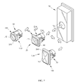
- FIG. 7 is a top perspective view of a series of interchangeable doorbell switch assemblies exploded away from a decorative plate having an unrecessed aperture;
- the doorbell switch assembly 10 depicted in FIGS. 1 and 2 of the drawings provides a push button doorbell switch 20 capable of being interchanged with other desirable push button shapes.
- An insert portion 30 of a push button switch 20 coincides with the dimensions and/or shapes of an aperture 52 of a decorative plate 50 allowing for interchangeability of a variety of push button switch apparatuses having insert 30 .
- the interchangeability of the push button switches allows for the user to interchange the push button doorbell switch 20 without having to purchase and install a new decorative plate.
- a plurality of varying doorbell button shapes can be used in a single decorative plate thereby increasing the variety of doorbell switch assemblies a user can choose from in selecting, changing, or upgrading the house décor.
- Exterior doors of homes and other dwellings are commonly equipped with doorbell switch assembly 10 by which a visitor may announce him or herself to those inside the dwelling.
- the doorbell switch assembly 10 may include push button switch 20 , decorative plate 50 , and a mounting base 60 .
- Decorative plate 50 may be releaseably mounted to base 60 of the doorbell assembly, or may otherwise be attached directly to an exterior wall 1 of the dwelling (not shown).
- the doorbell switch is operably connected, either by electrical wiring 2 ( FIGS. 2 , 3 ) or a wireless link, to an interior signaling device (not shown) such as an electromechanical ringer or electronic tone generator mounted inside the dwelling.
- the interior signaling device is actuated when an exterior doorbell push button 42 is pressed by a visitor or user.
- decorative plate 50 , base 60 , and push button switch 20 may be made of any metal including decorative material such as brass, bronze, aluminum, zinc, stainless steel, chrome, porcelain, plated steel, plastic, or any other material known to those skilled in the art.
- doorbell switch assembly 10 may be made from, or in part, of plastic or other suitable materials or in combination with other metal as described above.
- push button switch 20 includes an outer portion 40 and an insert or inner portion 30 .
- Outer portion 40 includes a push button or pad 42 which is substantially square in shape. Many other push button 42 shapes can be used in connection with the invention and still be within the scope thereof. For example, rectangular, polygon, round, or non-round shapes ( FIG. 7 ) may be employed as push button shapes.
- Outer portion 40 also comprises a flange 44 disposed around the perimeter of push button 42 .
- Insert 30 contains a plurality of outward projecting tabs 32 that are used in conjunction with flange 44 to maintain a fixed axial position of the push button switch 20 in relation to decorative plate 50 ( FIG. 3 ). As shown in FIGS.
- insert 30 is dimensioned and/or shaped to be received into an aperture 52 of decorative plate 50 .
- Insert 30 is substantially cylindrical in shape and congruent with the substantially cylindrical shape of aperture 52 . It should be understood that insert 30 may be a variety of different shapes and sizes and still be dimensioned to be received in a variety of corresponding shapes and sizes of aperture 52 .
- tabs 32 are forcibly retracted by the force of insertion (unless already in retracted position) into corresponding recess 33 to allow the tabs to pass thru aperture 52 while push button switch 20 is axially inserted into aperture 52 .
- the tabs may naturally return to their projecting configuration or may be manually forced outward to the projecting configuration.
- Tabs 32 are able to flex about a central pivot point 31 to travel from the closed or retracted configuration to an open or projecting configuration. The closed or retracted position of tabs 32 facilitates tabs 32 to be received within aperture 52 .
- tabs 32 The open or projecting position of tabs 32 facilitates tabs 32 to project radially from an exterior surface 35 of insert 30 to engage plate 50 .
- plate 50 surrounding aperture 52 becomes compressed between the plurality of tabs 32 and flange 44 which substantially minimizes the axial and/or rotational movement of push button switch 20 relative to decorative plate 50 .
- Flange 44 makes contact with an exterior surface 56 of plate 50 while the plurality of tabs 32 engages an interior surface 57 of plate 50 .
- electrical contacts 34 may be positioned on an end 36 of insert 30 .
- electrical contacts 34 may include, but are not limited to, wire sockets, wire clips, terminal blocks and the like.
- Electrical contacts 34 may be operably connected to the interior signaling device by electrically conductive wire 2 or wireless link.
- Push button switch 20 is normally electrically open. When the user manually depresses push button 42 , the switch is actuated and closes the open circuit and completes the electrical circuit between an electrical power source (not shown) and the interior signaling device (not shown) resulting in a signal, typically an audible sound.
- a user may pass electrical wire 2 through aperture 52 from within decorative plate 50 and subsequently affix to electrical contacts 34 before insertion of insert 30 into aperture 52 .
- decorative plate 50 has aperture 52 in which doorbell switch 20 is received.
- Decorative plate 50 may have a recess 54 in an exterior surface 56 which coincides with the shape of flange 44 of the push button switch 20 .
- Recess 54 operates to minimize rotational movement of switch 20 .
- Flange 44 and recess 54 may be substantially identical in shape, however the recess does not necessarily have to coincide in shape to be within the scope of the invention, as shown in FIG. 6 .
- recess 54 may not be included in exterior surface 56 of decorative plate 50 and still allow switch 20 to functionally interchange between a variety of decorative plates.
- Decorative plate 50 may be any number of different shapes and sizes and still be within the interchangeable design of push button switch 20 . As shown in FIGS. 1 , 2 , 5 , and 6 , decorative plate 50 may have exterior surface 56 that is substantially curved to enclose a portion of insert 30 . As shown in FIG. 7 , in another embodiment of the invention a decorative plate 70 is substantially flat and is without a recess surrounding an aperture 72 .
- the mechanism for minimizing the rotational and/or axial movement of switch 20 need not be in the form of tabs 32 .
- Base 60 may be attached to wall 1 or any exterior surface by any means known in the art, such as nails or screws.
- decorative plate 50 may be releaseably mounted to base 60 of the doorbell assembly 10 , or may otherwise be attached directly to exterior wall 1 of the dwelling (not shown). If decorative plate 50 is attached directly to a surface the plate is affixed thereto by screws or other conventional fasteners. When plate 50 is attached to base 60 , it may either be snapped or clipped into base 60 , or secured by any other fastening means known in the art. By mounting plate 50 to base 60 , the plate may be attached to the wall so as to minimize visible screw heads or the like, thus creating a surface uninterrupted by visible fastening means.
- push button pad 42 Numerous shapes and sizes of push button pad 42 can be used in conjunction with push button switch 20 , providing aperture 52 and insert 30 remain congruent in shape for interchangeability.
- decorative plate 50 can be assembled with a round button switch 120 with a square flange 144 of an outer portion 140 surrounding a round button 142 .
- a round button switch 122 has a round flange 154 of an outer portion 150 surrounding a round button 152 . Even though outer portion 150 of round button switch 122 does not coincide in shape with recess 54 , the present invention permits switch 122 to be interchanged with another switch apparatus.
- push button switch 20 may be received within unrecessed decorative plate 70 .
- push button switch 122 having a substantially round push button pad 152 and flange 154 may be received within unrecessed decorative plate 70 .
- a push button switch 124 having a substantially rectangular pad 162 and a flange 164 of an outer portion 160 may be received within unrecessed decorative plate 70 .
- the switches 20 , 122 , 124 can be used in a single decorative plate 70 because of the congruent shapes of insert 30 and aperture 72 of decorative plate 70 . As a result, a user can choose from a variety of doorbell push button shapes increasing the variety of doorbell switches a user can choose from in selecting, changing, or upgrading their house decor.
Landscapes
- Engineering & Computer Science (AREA)
- Manufacturing & Machinery (AREA)
- Rotary Switch, Piano Key Switch, And Lever Switch (AREA)
- Switch Cases, Indication, And Locking (AREA)
Abstract
Description
Claims (23)
Priority Applications (2)
| Application Number | Priority Date | Filing Date | Title |
|---|---|---|---|
| US11/555,788 US7714243B2 (en) | 2006-11-02 | 2006-11-02 | Push button doorbell switch apparatus |
| CA2608797A CA2608797C (en) | 2006-11-02 | 2007-10-30 | Push button doorbell switch apparatus |
Applications Claiming Priority (1)
| Application Number | Priority Date | Filing Date | Title |
|---|---|---|---|
| US11/555,788 US7714243B2 (en) | 2006-11-02 | 2006-11-02 | Push button doorbell switch apparatus |
Publications (2)
| Publication Number | Publication Date |
|---|---|
| US20080105523A1 US20080105523A1 (en) | 2008-05-08 |
| US7714243B2 true US7714243B2 (en) | 2010-05-11 |
Family
ID=39358805
Family Applications (1)
| Application Number | Title | Priority Date | Filing Date |
|---|---|---|---|
| US11/555,788 Active 2028-08-17 US7714243B2 (en) | 2006-11-02 | 2006-11-02 | Push button doorbell switch apparatus |
Country Status (2)
| Country | Link |
|---|---|
| US (1) | US7714243B2 (en) |
| CA (1) | CA2608797C (en) |
Cited By (13)
| Publication number | Priority date | Publication date | Assignee | Title |
|---|---|---|---|---|
| USD645005S1 (en) * | 2010-09-30 | 2011-09-13 | HAPP Controls, Inc. | Round push button |
| USD645004S1 (en) * | 2010-09-30 | 2011-09-13 | HAPP Controls, Inc. | Rectangular push button |
| US20120057314A1 (en) * | 2010-09-03 | 2012-03-08 | Hon Hai Precision Industry Co., Ltd. | Push-button switch assembly and electronic device with same |
| USD663700S1 (en) * | 2010-06-03 | 2012-07-17 | Deal Steven A | Call button |
| USD708388S1 (en) * | 2013-11-27 | 2014-07-01 | Heathco, Llc | Curved light fixture |
| USD735927S1 (en) | 2013-11-27 | 2015-08-04 | Heathco, Llc | Curved light fixture |
| USD830081S1 (en) * | 2015-03-27 | 2018-10-09 | Hunter Douglas Inc. | Button for a window covering |
| USD835335S1 (en) | 2017-04-26 | 2018-12-04 | Heathco Llc | Security light |
| USD835834S1 (en) | 2017-04-26 | 2018-12-11 | Heathco Llc | Security light |
| USD885355S1 (en) * | 2018-07-11 | 2020-05-26 | Omron Corporation | Push button for switch |
| US10832534B1 (en) * | 2019-07-09 | 2020-11-10 | Rahsaan Currie | Doorbell customization assembly |
| USD942774S1 (en) | 2015-03-27 | 2022-02-08 | Hunter Douglas Inc | Button for a window covering |
| US20220270449A1 (en) * | 2021-02-19 | 2022-08-25 | SimpliSafe, Inc. | Doorbell mounting and activation apparatus and method |
Families Citing this family (3)
| Publication number | Priority date | Publication date | Assignee | Title |
|---|---|---|---|---|
| US8536991B2 (en) * | 2011-06-02 | 2013-09-17 | Spencer O. Gilbert | Wireless decorative doorbell device |
| JP5841832B2 (en) * | 2011-12-21 | 2016-01-13 | アイホン株式会社 | Intercom equipment |
| US11143372B1 (en) * | 2021-06-10 | 2021-10-12 | Steve Wriggle | Safety device cabinet with a safety switch having an integrated light |
Citations (6)
| Publication number | Priority date | Publication date | Assignee | Title |
|---|---|---|---|---|
| US3084962A (en) * | 1960-04-06 | 1963-04-09 | Trine Mfg Corp | Fastener means |
| US4840584A (en) * | 1988-02-05 | 1989-06-20 | Michael Cox | Mounting plate for attachment of electrical controls and accessories to walls and the like |
| US20030094358A1 (en) * | 2001-11-08 | 2003-05-22 | Jeanette Bui | Doorbell assembly with hidden fastener |
| US6590176B2 (en) * | 2001-03-12 | 2003-07-08 | Joseph W. Cole | Push-button type electrical switch |
| US20030169178A1 (en) * | 2002-02-15 | 2003-09-11 | Jensen Bradford B. | Marker lights for wireless doorbell transmitters and other devices |
| US7180021B2 (en) | 2005-04-05 | 2007-02-20 | Desa Ip, Llc | LED illuminated door chime push button with adjustable task light |
-
2006
- 2006-11-02 US US11/555,788 patent/US7714243B2/en active Active
-
2007
- 2007-10-30 CA CA2608797A patent/CA2608797C/en not_active Expired - Fee Related
Patent Citations (7)
| Publication number | Priority date | Publication date | Assignee | Title |
|---|---|---|---|---|
| US3084962A (en) * | 1960-04-06 | 1963-04-09 | Trine Mfg Corp | Fastener means |
| US4840584A (en) * | 1988-02-05 | 1989-06-20 | Michael Cox | Mounting plate for attachment of electrical controls and accessories to walls and the like |
| US6590176B2 (en) * | 2001-03-12 | 2003-07-08 | Joseph W. Cole | Push-button type electrical switch |
| US20030094358A1 (en) * | 2001-11-08 | 2003-05-22 | Jeanette Bui | Doorbell assembly with hidden fastener |
| US6828519B2 (en) * | 2001-11-08 | 2004-12-07 | Newfry Llc | Doorbell assembly with hidden fastener |
| US20030169178A1 (en) * | 2002-02-15 | 2003-09-11 | Jensen Bradford B. | Marker lights for wireless doorbell transmitters and other devices |
| US7180021B2 (en) | 2005-04-05 | 2007-02-20 | Desa Ip, Llc | LED illuminated door chime push button with adjustable task light |
Cited By (24)
| Publication number | Priority date | Publication date | Assignee | Title |
|---|---|---|---|---|
| USD663700S1 (en) * | 2010-06-03 | 2012-07-17 | Deal Steven A | Call button |
| US20120057314A1 (en) * | 2010-09-03 | 2012-03-08 | Hon Hai Precision Industry Co., Ltd. | Push-button switch assembly and electronic device with same |
| US8493742B2 (en) * | 2010-09-03 | 2013-07-23 | Hong Fu Jin Precision Industry (Shenzhen) Co., Ltd. | Push-button switch assembly and electronic device with same |
| USD645005S1 (en) * | 2010-09-30 | 2011-09-13 | HAPP Controls, Inc. | Round push button |
| USD645004S1 (en) * | 2010-09-30 | 2011-09-13 | HAPP Controls, Inc. | Rectangular push button |
| USD708388S1 (en) * | 2013-11-27 | 2014-07-01 | Heathco, Llc | Curved light fixture |
| USD720093S1 (en) | 2013-11-27 | 2014-12-23 | Heathco, Llc | Curved light fixture |
| USD735927S1 (en) | 2013-11-27 | 2015-08-04 | Heathco, Llc | Curved light fixture |
| USD942775S1 (en) | 2015-03-27 | 2022-02-08 | Hunter Douglas Inc. | Button for a window covering |
| USD830081S1 (en) * | 2015-03-27 | 2018-10-09 | Hunter Douglas Inc. | Button for a window covering |
| USD942774S1 (en) | 2015-03-27 | 2022-02-08 | Hunter Douglas Inc | Button for a window covering |
| USRE48869E1 (en) | 2017-04-26 | 2022-01-04 | Heathco Llc | Security light |
| USRE48362E1 (en) | 2017-04-26 | 2020-12-22 | Heathco Llc | Security light |
| USRE48386E1 (en) | 2017-04-26 | 2021-01-12 | Heathco Llc | Security light |
| USD835335S1 (en) | 2017-04-26 | 2018-12-04 | Heathco Llc | Security light |
| USRE48886E1 (en) | 2017-04-26 | 2022-01-11 | Heathco Llc | Security light |
| USRE48885E1 (en) | 2017-04-26 | 2022-01-11 | Heathco Llc | Security light |
| USD835834S1 (en) | 2017-04-26 | 2018-12-11 | Heathco Llc | Security light |
| USRE48987E1 (en) | 2017-04-26 | 2022-03-29 | Heathco Llc | Security light |
| USD885355S1 (en) * | 2018-07-11 | 2020-05-26 | Omron Corporation | Push button for switch |
| US10832534B1 (en) * | 2019-07-09 | 2020-11-10 | Rahsaan Currie | Doorbell customization assembly |
| US20220270449A1 (en) * | 2021-02-19 | 2022-08-25 | SimpliSafe, Inc. | Doorbell mounting and activation apparatus and method |
| US11941973B2 (en) * | 2021-02-19 | 2024-03-26 | SimpliSafe, Inc. | Doorbell mounting and activation apparatus and method |
| US12243413B2 (en) | 2021-02-19 | 2025-03-04 | SimpliSafe, Inc. | Doorbell mounting and activation apparatus and method |
Also Published As
| Publication number | Publication date |
|---|---|
| US20080105523A1 (en) | 2008-05-08 |
| CA2608797C (en) | 2014-02-18 |
| CA2608797A1 (en) | 2008-05-02 |
Similar Documents
| Publication | Publication Date | Title |
|---|---|---|
| CA2608797C (en) | Push button doorbell switch apparatus | |
| US6750760B2 (en) | Door chime assembly and method | |
| US6979790B2 (en) | Rocker paddle switch with flexible cam driver | |
| US9543093B2 (en) | Universal box system | |
| US20070235205A9 (en) | Receptacle with shaped surface | |
| US20050115818A1 (en) | Switch with shaped face | |
| US7282642B2 (en) | Shaped wall plate for wiring device | |
| US7122754B2 (en) | Rocker paddle switch with articulated cam driver | |
| US20050121221A1 (en) | Alignment plate for wiring device | |
| US7265308B2 (en) | Rocker paddle switch with semi-rigid cam driver | |
| US7126070B2 (en) | Rocker paddle switch with flexible cam driver | |
| US9920912B1 (en) | Lighting device | |
| US20050109527A1 (en) | Wall plate with one opening for one of more wiring devices | |
| US2529234A (en) | Keyhole illuminator | |
| CN1126130C (en) | Electric device for evaporating active subsrtances | |
| US5392202A (en) | Low profile illuminated push button | |
| US4285033A (en) | Lampholder--switch module | |
| US7244891B2 (en) | Shaped wall plate for wiring device | |
| KR101610865B1 (en) | Lamp base apparatus with non-rotating isolation structure and Lamp using the same | |
| CN213451957U (en) | Micro-gap switch mounting structure and plug valve assembly | |
| KR200401427Y1 (en) | A speaker housing | |
| EP1510295A3 (en) | Cable mount and fixture having electrical switch assembly | |
| KR101685988B1 (en) | Power distribution structure for LED laid wall ing apartment house |
Legal Events
| Date | Code | Title | Description |
|---|---|---|---|
| AS | Assignment |
Owner name: DESA IP, LLC, FLORIDA Free format text: ASSIGNMENT OF ASSIGNORS INTEREST;ASSIGNOR:BIRDWELL, TIMOTHY GALE;REEL/FRAME:018472/0517 Effective date: 20061024 Owner name: DESA IP, LLC,FLORIDA Free format text: ASSIGNMENT OF ASSIGNORS INTEREST;ASSIGNOR:BIRDWELL, TIMOTHY GALE;REEL/FRAME:018472/0517 Effective date: 20061024 |
|
| AS | Assignment |
Owner name: HEATHCO LLC, ILLINOIS Free format text: ASSIGNMENT OF ASSIGNORS INTEREST;ASSIGNOR:DESA IP, LLC;REEL/FRAME:020010/0766 Effective date: 20070828 Owner name: HEATHCO LLC,ILLINOIS Free format text: ASSIGNMENT OF ASSIGNORS INTEREST;ASSIGNOR:DESA IP, LLC;REEL/FRAME:020010/0766 Effective date: 20070828 |
|
| STCF | Information on status: patent grant |
Free format text: PATENTED CASE |
|
| FPAY | Fee payment |
Year of fee payment: 4 |
|
| AS | Assignment |
Owner name: LBC CREDIT PARTNERS III, L.P., AS AGENT, PENNSYLVA Free format text: SECURITY INTEREST;ASSIGNOR:HEATHCO LLC;REEL/FRAME:037484/0127 Effective date: 20160111 |
|
| AS | Assignment |
Owner name: WELLS FARGO BANK, NATIONAL ASSOCIATION, CALIFORNIA Free format text: PATENT SECURITY AGREEMENT;ASSIGNOR:HEATHCO LLC;REEL/FRAME:037693/0533 Effective date: 20160111 |
|
| FEPP | Fee payment procedure |
Free format text: PAT HOLDER CLAIMS SMALL ENTITY STATUS, ENTITY STATUS SET TO SMALL (ORIGINAL EVENT CODE: LTOS); ENTITY STATUS OF PATENT OWNER: SMALL ENTITY |
|
| MAFP | Maintenance fee payment |
Free format text: PAYMENT OF MAINTENANCE FEE, 8TH YR, SMALL ENTITY (ORIGINAL EVENT CODE: M2552) Year of fee payment: 8 |
|
| AS | Assignment |
Owner name: HEATHCO LLC, KENTUCKY Free format text: RELEASE BY SECURED PARTY;ASSIGNOR:LBC CREDIT PARTNERS III, L.P., AS AGENT;REEL/FRAME:055349/0140 Effective date: 20201014 |
|
| AS | Assignment |
Owner name: HEATHCO LLC, KENTUCKY Free format text: RELEASE BY SECURED PARTY;ASSIGNOR:WELLS FARGO BANK, NATIONAL ASSOCIATION;REEL/FRAME:057946/0154 Effective date: 20211008 |
|
| MAFP | Maintenance fee payment |
Free format text: PAYMENT OF MAINTENANCE FEE, 12TH YR, SMALL ENTITY (ORIGINAL EVENT CODE: M2553); ENTITY STATUS OF PATENT OWNER: SMALL ENTITY Year of fee payment: 12 |
|
| AS | Assignment |
Owner name: THE TORONTO-DOMINION BANK, CANADA Free format text: SECURITY INTEREST;ASSIGNOR:HEATHCO LLC;REEL/FRAME:058980/0186 Effective date: 20211216 |
|
| AS | Assignment |
Owner name: ALTER DOMUS (US) LLC, ILLINOIS Free format text: ASSIGNMENT FOR SECURITY - PATENTS AND INDUSTRIAL DESIGNS;ASSIGNORS:GLOBE ELECTRIC COMPANY INC.;HEATHCO LLC;REEL/FRAME:068235/0742 Effective date: 20240725 |
|
| AS | Assignment |
Owner name: BANK OF AMERICA, N.A., NEW YORK Free format text: ASSIGNMENT FOR SECURITY - PATENTS AND INDUSTRIAL DESIGNS;ASSIGNORS:GLOBE ELECTRIC COMPANY INC.;HEATHCO LLC;REEL/FRAME:068235/0716 Effective date: 20240725 |
|
| AS | Assignment |
Owner name: HEATHCO, LLC, KENTUCKY Free format text: RELEASE BY SECURED PARTY;ASSIGNOR:TORONTO-DOMINION BANK;REEL/FRAME:068654/0433 Effective date: 20240726 Owner name: GLOBE ELECTRIC COMPANY INC., CANADA Free format text: RELEASE BY SECURED PARTY;ASSIGNOR:TORONTO-DOMINION BANK;REEL/FRAME:068654/0433 Effective date: 20240726 |