US7712697B1 - Core winding apparatus and method of winding a core - Google Patents
Core winding apparatus and method of winding a core Download PDFInfo
- Publication number
- US7712697B1 US7712697B1 US12/478,829 US47882909A US7712697B1 US 7712697 B1 US7712697 B1 US 7712697B1 US 47882909 A US47882909 A US 47882909A US 7712697 B1 US7712697 B1 US 7712697B1
- Authority
- US
- United States
- Prior art keywords
- winding
- wire
- wraps
- teeth
- core
- Prior art date
- Legal status (The legal status is an assumption and is not a legal conclusion. Google has not performed a legal analysis and makes no representation as to the accuracy of the status listed.)
- Active
Links
Images


Classifications
-
- H—ELECTRICITY
- H02—GENERATION; CONVERSION OR DISTRIBUTION OF ELECTRIC POWER
- H02K—DYNAMO-ELECTRIC MACHINES
- H02K15/00—Processes or apparatus specially adapted for manufacturing, assembling, maintaining or repairing of dynamo-electric machines
- H02K15/08—Forming windings by laying conductors into or around core parts
- H02K15/095—Forming windings by laying conductors into or around core parts by laying conductors around salient poles
Definitions
- the subject matter disclosed herein relates to the art of electrical machines and, more particularly, to a core winding apparatus and method of winding a core.
- stator cores are wound with round wire.
- the stator core is held stationary and the round wire is fed through a winding needle that is rotated about a stator tooth. Once the stator tooth is wound, the wire is advanced to a subsequent stator tooth.
- the winding needle not only travels along a circular path but also moves in and out to layer the wire. Upon exiting the winding needle, the wire twists as a result of rotational forces developed while traveling along the circular path.
- an apparatus for winding wire about a tooth of a core includes an amount of wire, a winding member configured to receive a portion of the amount of wire, and a winding device operatively coupled to the winding member.
- the winding member being configured to apply a number of wraps of the amount of wire to each of at least one of a plurality of stator teeth of the full stator core.
- the number of wraps including a number of twists that is fewer than the number of wraps.
- a method of winding a core having a plurality of teeth includes passing a portion of the length of wire through a winding member, and applying a number of wraps of the wire to at least one of the plurality of teeth.
- the wraps of wire including a number of twists that is fewer than the number of wraps.
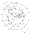
- FIG. 1 is an elevational view of a core being wound by a core winding apparatus in accordance with an exemplary embodiment
- FIG. 2 is an elevational view of a rectangular wire in a first orientation being applied without twisting to a tooth of the core of FIG. 1 ;
- FIG. 3 is an elevational view of the rectangular wire of FIG. 2 in a second orientation being applied without twisting to a tooth of the core of FIG. 1 ;
- FIG. 4 is an elevational view of the rectangular wire of FIG. 3 in a third orientation being applied without twisting to a tooth of the core of FIG. 1 ;
- FIG. 5 is an elevational view of the rectangular wire of FIG. 4 in a third orientation being applied without twisting to a tooth of the core of FIG. 1 .
- a core shown in the form of a full stator core configured to be wound in accordance with an exemplary embodiment is indicated generally at 2 .
- Stator core 2 includes a main body 4 having an inner diameter 5 provided with a plurality of stator teeth, one of which is indicated at 6 .
- Stator teeth 6 are arranged in a series of poles, e.g., A 1 -A 4 ; B 1 -B 4 ; and C 1 -C 4 that collectively define electrical phases A, B, and C.
- Each stator tooth includes a main body 8 having a first substantially planar surface 14 , a second substantially planar surface 15 , a third substantially planar surface 16 , and a fourth substantially planar surface 17 ( FIG.
- each stator tooth 6 includes a central axis 20 that passes from a central point of inner diameter 5 radially through each stator tooth 6 .
- each stator tooth 6 is wound with wire in order to achieve a necessary magnetic field to operate an associated electric machine.
- stator core 2 is wound using a winding apparatus 30 that is arranged entirely within inner diameter 5 .
- Winding apparatus 30 includes a winding device 32 provided with a bobbin 34 and a winding member shown in the form of a winding needle 36 .
- bobbin refers to any device that is configured to retain a selected amount of wire.
- Winding needle 36 includes a first end 38 that extends to a second end 40 .
- Winding apparatus 30 also includes a winding element 44 that is operatively connected to winding needle 36 .
- bobbin 34 is wound with a selected amount of wire 60 that includes a plurality of sides 62 - 65 to define a rectangular cross-section.
- Winding apparatus 30 is selectively operated in order to wrap each of the plurality of stator teeth 6 with a continuous, untwisted length of wire 60 .
- bobbin 34 is loaded with enough wire 60 to wrap, for example each of poles A 1 -A 4 in a single winding operation. As such, each stator tooth corresponding to poles A 1 -A 4 is wrapped with a continuous piece of untwisted wire in a manner that will be described more fully below.
- winding device 32 translates about each of the plurality of stator teeth 6 wrapping wire 60 about planar surfaces 14 - 17 .
- winding element 44 rotates winding needle 36 causing only one of the plurality of sides 62 - 65 of wire 60 to face each planar surface 14 - 17 of stator tooth 6 .
- winding device 32 is configured to be rotated about a longitudinal axis defined by winding needle 36 . In this manner, stator tooth 6 is wrapped with a number of wraps of wire, with the wire having fewer twists than the total number of wraps.
- the number of twists will be one fewer than the total number of wraps. In accordance with another aspect of the invention, the number of twists will be between one fewer and half the total number of wraps. In accordance with yet another aspect, the number of twists will be fewer than half of the number of wraps. In accordance with still another aspect of the invention, the wire will remain untwisted. In any case, stator tooth 6 will be wrapped with rectangular wire having few twists to enable a tight spacing of wire to minimize an overall form factor of stator core 2 . More specifically, as shown in FIG. 2 , winding needle 36 positions side 64 of wire 60 facing surface 14 of stator tooth 6 . Winding device 32 then translates about stator tooth 6 positioning winding needle 36 adjacent surface 15 .
- winding element 44 rotates causing side 64 of wire 60 to face surface 15 .
- FIG. 4 continued translation of winding device 32 results in a corresponding rotation of winding element 44 such that side 64 faces surface 16 of stator tooth 6 .
- FIG. 5 side 64 also faces fourth surface 17 before the wrap is completed.
- winding apparatus 30 oscillates along a substantially linear path defined by axis 20 . In this manner, consecutive adjacent wraps are applied and layered in order to apply predetermined amount of wire to each stator tooth.
- an exemplary embodiment provides an apparatus and method of applying a wire, particularly wire having a rectangular cross-section, to a stator tooth. More specifically, the apparatus and method enables a continuous, uninterrupted and untwisted application of wire to a number of stator teeth in order to enhance manufacturing efficiencies and provide a more compact profile on each stator tooth. This is, instead of using round wire, which tends to twist and create bulk, the apparatus of the present invention fits entirely within a full stator core so as to apply a continuous, untwisted length of rectangular wire. In this manner, the stator core will be formed having a smaller profile thereby enabling the construction of even smaller electric machines.
- exemplary embodiments provide a stator core having a minimal number of connections between the stator teeth and a phase lead. Also, while described in connection with a full stator core, it should be understood that the exemplary embodiment can also be employed to wind armatures, segmented cores, flexible cores, rotating cores, stationary cores and the like. In addition, while the winding member is described as a winding needle, various other devices configured to feed wire onto a core tooth can be employed.
Landscapes
- Engineering & Computer Science (AREA)
- Manufacturing & Machinery (AREA)
- Power Engineering (AREA)
- Manufacture Of Motors, Generators (AREA)
Abstract
Description
Claims (16)
Priority Applications (4)
| Application Number | Priority Date | Filing Date | Title |
|---|---|---|---|
| US12/478,829 US7712697B1 (en) | 2009-06-05 | 2009-06-05 | Core winding apparatus and method of winding a core |
| DE102010029688A DE102010029688A1 (en) | 2009-06-05 | 2010-06-03 | Core winding apparatus and method for winding a core |
| KR1020100052760A KR20100131379A (en) | 2009-06-05 | 2010-06-04 | Core winding device and core winding method |
| CN2010101983774A CN101908800A (en) | 2009-06-05 | 2010-06-07 | The method of wind unshakable in one's determination and wound core |
Applications Claiming Priority (1)
| Application Number | Priority Date | Filing Date | Title |
|---|---|---|---|
| US12/478,829 US7712697B1 (en) | 2009-06-05 | 2009-06-05 | Core winding apparatus and method of winding a core |
Publications (1)
| Publication Number | Publication Date |
|---|---|
| US7712697B1 true US7712697B1 (en) | 2010-05-11 |
Family
ID=42139234
Family Applications (1)
| Application Number | Title | Priority Date | Filing Date |
|---|---|---|---|
| US12/478,829 Active US7712697B1 (en) | 2009-06-05 | 2009-06-05 | Core winding apparatus and method of winding a core |
Country Status (4)
| Country | Link |
|---|---|
| US (1) | US7712697B1 (en) |
| KR (1) | KR20100131379A (en) |
| CN (1) | CN101908800A (en) |
| DE (1) | DE102010029688A1 (en) |
Cited By (4)
| Publication number | Priority date | Publication date | Assignee | Title |
|---|---|---|---|---|
| US20090001209A1 (en) * | 2006-03-13 | 2009-01-01 | Atop S.P.A. | Apparatus and Methods for Winding Wire Coils of Dynamoelectric Machine Cores |
| US20110072652A1 (en) * | 2009-06-05 | 2011-03-31 | Remy Technologies, L.L.C. | Method of winding a plurality of stator teeth of a segmented stator core |
| US20110148243A1 (en) * | 2009-12-17 | 2011-06-23 | Remy Technologies, L.L.C. | Stator core for an electric machine |
| CN104300749A (en) * | 2014-10-30 | 2015-01-21 | 南车株洲电机有限公司 | Motor cable inserting device and motor cable inserting method |
Families Citing this family (1)
| Publication number | Priority date | Publication date | Assignee | Title |
|---|---|---|---|---|
| DE102016219051A1 (en) * | 2016-09-30 | 2018-04-05 | Robert Bosch Gmbh | Electric motor for driving an ABS system |
Citations (14)
| Publication number | Priority date | Publication date | Assignee | Title |
|---|---|---|---|---|
| US6530140B2 (en) * | 1997-10-16 | 2003-03-11 | Denso Corporation | Method and apparatus for manufacturing AC-generator's stator for vehicle |
| US6553650B2 (en) * | 1998-02-12 | 2003-04-29 | Toyota Jidosha Kabushiki Kaisha | Method for manufacturing a rectangular-wire coil |
| US20030089812A1 (en) * | 2001-11-13 | 2003-05-15 | Hideaki Iwase | Wire winding apparatus and method for manufacturing armature |
| US20040173710A1 (en) * | 2002-12-09 | 2004-09-09 | Gianfranco Stratico | Multiple wire winding |
| US20050029385A1 (en) * | 2003-02-13 | 2005-02-10 | Gianfranco Stratico | Dynamo-electric core winder |
| US6865796B1 (en) * | 2000-02-23 | 2005-03-15 | Mitsubishi Denki Kabushiki Kaisha | Method of manufacturing a stator for an alternator with reduced conductor portions |
| US20050133655A1 (en) | 2002-08-08 | 2005-06-23 | Shingo Hashimoto | Coil forming method and coil forming device |
| US20050247815A1 (en) * | 2003-10-15 | 2005-11-10 | Actown Electrocoil, Inc. | Magnetic core winding method |
| US20060169822A1 (en) * | 2004-09-13 | 2006-08-03 | Kaoru Noji | Winding method of multi polar armature and winding apparatus of same |
| US7213784B2 (en) | 2002-01-30 | 2007-05-08 | Ab Underphone | Plastic bobbin and a method of manufacturing such a bobbin |
| US20080203213A1 (en) | 2007-02-26 | 2008-08-28 | Nittoku Engineering Co., Ltd. | Winding device and winding method for multi polar armature |
| US20090057473A1 (en) * | 2007-08-27 | 2009-03-05 | Nittoku Engineering Co., Ltd | Winding device |
| US20090065623A1 (en) * | 2004-10-22 | 2009-03-12 | Thales | Device and method for winding a coil of rigid wire around a ring core |
| US7543774B2 (en) * | 2002-10-04 | 2009-06-09 | Robert Bosch Gmbh | Coiling machine and method for the production of a coil |
Family Cites Families (2)
| Publication number | Priority date | Publication date | Assignee | Title |
|---|---|---|---|---|
| JP3177193B2 (en) * | 1997-07-02 | 2001-06-18 | 日特エンジニアリング株式会社 | Winding machine and winding method |
| JP4259127B2 (en) * | 2002-07-30 | 2009-04-30 | アイシン・エィ・ダブリュ株式会社 | Manufacturing method of motor |
-
2009
- 2009-06-05 US US12/478,829 patent/US7712697B1/en active Active
-
2010
- 2010-06-03 DE DE102010029688A patent/DE102010029688A1/en not_active Withdrawn
- 2010-06-04 KR KR1020100052760A patent/KR20100131379A/en not_active Withdrawn
- 2010-06-07 CN CN2010101983774A patent/CN101908800A/en active Pending
Patent Citations (20)
| Publication number | Priority date | Publication date | Assignee | Title |
|---|---|---|---|---|
| US6530140B2 (en) * | 1997-10-16 | 2003-03-11 | Denso Corporation | Method and apparatus for manufacturing AC-generator's stator for vehicle |
| US6553650B2 (en) * | 1998-02-12 | 2003-04-29 | Toyota Jidosha Kabushiki Kaisha | Method for manufacturing a rectangular-wire coil |
| US6865796B1 (en) * | 2000-02-23 | 2005-03-15 | Mitsubishi Denki Kabushiki Kaisha | Method of manufacturing a stator for an alternator with reduced conductor portions |
| US6712307B2 (en) * | 2001-11-13 | 2004-03-30 | Asmo Co., Ltd. | Wire winding apparatus and method for manufacturing armature |
| US20030089812A1 (en) * | 2001-11-13 | 2003-05-15 | Hideaki Iwase | Wire winding apparatus and method for manufacturing armature |
| US7213784B2 (en) | 2002-01-30 | 2007-05-08 | Ab Underphone | Plastic bobbin and a method of manufacturing such a bobbin |
| US20050133655A1 (en) | 2002-08-08 | 2005-06-23 | Shingo Hashimoto | Coil forming method and coil forming device |
| US7543774B2 (en) * | 2002-10-04 | 2009-06-09 | Robert Bosch Gmbh | Coiling machine and method for the production of a coil |
| US20040173710A1 (en) * | 2002-12-09 | 2004-09-09 | Gianfranco Stratico | Multiple wire winding |
| US20060273214A1 (en) * | 2002-12-09 | 2006-12-07 | Axis Usa, Inc. | Multiple wire winding |
| US20050029385A1 (en) * | 2003-02-13 | 2005-02-10 | Gianfranco Stratico | Dynamo-electric core winder |
| US7004420B2 (en) * | 2003-02-13 | 2006-02-28 | Atop S.P.A. | Dynamo-electric core winder |
| US20050247815A1 (en) * | 2003-10-15 | 2005-11-10 | Actown Electrocoil, Inc. | Magnetic core winding method |
| US7159816B2 (en) * | 2003-10-15 | 2007-01-09 | Actown Electricoil, Inc. | Magnetic core winding method |
| US20060169822A1 (en) * | 2004-09-13 | 2006-08-03 | Kaoru Noji | Winding method of multi polar armature and winding apparatus of same |
| US20070181732A1 (en) * | 2004-09-13 | 2007-08-09 | Nittoku Engineering Kabushiki Kaisha | Winding method of multi polar armature and winding apparatus of same |
| US7243873B2 (en) * | 2004-09-13 | 2007-07-17 | Nittoku Engineering Kabushiki Kaisha | Winding method of multi polar armature and winding apparatus of same |
| US20090065623A1 (en) * | 2004-10-22 | 2009-03-12 | Thales | Device and method for winding a coil of rigid wire around a ring core |
| US20080203213A1 (en) | 2007-02-26 | 2008-08-28 | Nittoku Engineering Co., Ltd. | Winding device and winding method for multi polar armature |
| US20090057473A1 (en) * | 2007-08-27 | 2009-03-05 | Nittoku Engineering Co., Ltd | Winding device |
Cited By (6)
| Publication number | Priority date | Publication date | Assignee | Title |
|---|---|---|---|---|
| US20090001209A1 (en) * | 2006-03-13 | 2009-01-01 | Atop S.P.A. | Apparatus and Methods for Winding Wire Coils of Dynamoelectric Machine Cores |
| US8424792B2 (en) | 2006-03-13 | 2013-04-23 | Atop S.P.A. | Apparatus and methods for winding wire coils of dynamoelectric machine cores |
| US20110072652A1 (en) * | 2009-06-05 | 2011-03-31 | Remy Technologies, L.L.C. | Method of winding a plurality of stator teeth of a segmented stator core |
| US20110148243A1 (en) * | 2009-12-17 | 2011-06-23 | Remy Technologies, L.L.C. | Stator core for an electric machine |
| US8614530B2 (en) | 2009-12-17 | 2013-12-24 | Remy Technologies, L.L.C. | Stator core for an electric machine |
| CN104300749A (en) * | 2014-10-30 | 2015-01-21 | 南车株洲电机有限公司 | Motor cable inserting device and motor cable inserting method |
Also Published As
| Publication number | Publication date |
|---|---|
| CN101908800A (en) | 2010-12-08 |
| KR20100131379A (en) | 2010-12-15 |
| DE102010029688A1 (en) | 2011-01-13 |
Similar Documents
| Publication | Publication Date | Title |
|---|---|---|
| US9077216B2 (en) | Stator for rotating electrical machine | |
| US20090072653A1 (en) | Stator Structure of Rotary Electric Machine and Method of Manufacturing the Same | |
| US8890388B2 (en) | Winding structure for a rectangular wire | |
| US8058766B2 (en) | Electric rotational motor | |
| CA2695059C (en) | Single-layer coil with one bent endwinding and one straight enwinding | |
| CN106208430B (en) | Stator assembly for three-phase electric motor and related winding method | |
| JP5625936B2 (en) | Rotating electric machine | |
| US20080010812A1 (en) | Method of forming single-layer coils | |
| CN101989777B (en) | Motor and method of manufacturing motor | |
| US20120205482A1 (en) | Winding method for producing electric coils | |
| JP2012235587A5 (en) | ||
| US10574111B2 (en) | Rotating electric machine with lane-changed coils | |
| US7712697B1 (en) | Core winding apparatus and method of winding a core | |
| US20150022048A1 (en) | Rotating electrical machine armature | |
| US7694909B1 (en) | Method of winding a flexible core | |
| JP5768305B1 (en) | Stator manufacturing method and apparatus | |
| TR201809566T4 (en) | An electric machine having a winding for forming a rotating field and a method for manufacturing the winding. | |
| CN117296230A (en) | Rotating electromechanical equipment and method of manufacturing stator windings | |
| US20140285055A1 (en) | Wound member for manufacturing coil, coil, rotating electrical machine, and method for manufacturing coil | |
| US8614530B2 (en) | Stator core for an electric machine | |
| JP2008172863A (en) | Rotating electric machine and manufacturing method thereof | |
| US20100133945A1 (en) | Segmented stator core winding apparatus and method of winding a segmented stator core | |
| CN109428423A (en) | Stator and its manufacturing method, motor and its manufacturing method, method for winding | |
| TR201809568T4 (en) | Tile set. | |
| JP5290731B2 (en) | Armature winding method and armature |
Legal Events
| Date | Code | Title | Description |
|---|---|---|---|
| AS | Assignment |
Owner name: REMY TECHNOLOGIES, L.L.C.,INDIANA Free format text: ASSIGNMENT OF ASSIGNORS INTEREST;ASSIGNORS:CHAMBERLIN, BRADLEY D.;STEPHENSON, MARK A.;KUBES, LARRY A.;REEL/FRAME:022785/0478 Effective date: 20090604 |
|
| STCF | Information on status: patent grant |
Free format text: PATENTED CASE |
|
| AS | Assignment |
Owner name: BANK OF AMERICA, N.A., AS ADMINISTRATIVE AGENT, NO Free format text: GRANT OF PATENT SECURITY INTEREST;ASSIGNOR:REMY TECHNOLOGIES, L.L.C.;REEL/FRAME:025521/0387 Effective date: 20101217 |
|
| AS | Assignment |
Owner name: WELLS FARGO CAPITAL FINANCE, LLC, AS AGENT, ILLINO Free format text: SECURITY AGREEMENT;ASSIGNORS:REMY TECHNOLOGIES, L.L.C.;REMY POWER PRODUCTS, LLC;REEL/FRAME:025525/0186 Effective date: 20101217 |
|
| FPAY | Fee payment |
Year of fee payment: 4 |
|
| AS | Assignment |
Owner name: REMY POWER PRODUCTS, L.L.C., INDIANA Free format text: RELEASE OF SECURITY INTEREST IN PATENTS PREVIOUSLY RECORDED AT REEL/FRAME 025525/0186;ASSIGNOR:WELLS FARGO CAPITAL FINANCE, L.L.C.;REEL/FRAME:037108/0618 Effective date: 20151110 Owner name: REMY TECHNOLOGIES, L.L.C., INDIANA Free format text: RELEASE OF SECURITY INTEREST IN PATENTS PREVIOUSLY RECORDED AT REEL/FRAME 025525/0186;ASSIGNOR:WELLS FARGO CAPITAL FINANCE, L.L.C.;REEL/FRAME:037108/0618 Effective date: 20151110 Owner name: REMY TECHNOLOGIES, L.L.C., INDIANA Free format text: RELEASE OF SECURITY INTEREST IN PATENTS PREVIOUSLY RECORDED AT REEL/FRAME 025521/0387;ASSIGNOR:BANK OF AMERICA, N.A.;REEL/FRAME:037101/0125 Effective date: 20151110 |
|
| AS | Assignment |
Owner name: BORGWARNER INC., MICHIGAN Free format text: ASSIGNMENT OF ASSIGNORS INTEREST;ASSIGNOR:REMY TECHNOLOGIES, L.L.C.;REEL/FRAME:043539/0619 Effective date: 20170811 |
|
| MAFP | Maintenance fee payment |
Free format text: PAYMENT OF MAINTENANCE FEE, 8TH YEAR, LARGE ENTITY (ORIGINAL EVENT CODE: M1552) Year of fee payment: 8 |
|
| MAFP | Maintenance fee payment |
Free format text: PAYMENT OF MAINTENANCE FEE, 12TH YEAR, LARGE ENTITY (ORIGINAL EVENT CODE: M1553); ENTITY STATUS OF PATENT OWNER: LARGE ENTITY Year of fee payment: 12 |