US7702450B2 - Automatic idle adjustment and shutdown of vehicle - Google Patents
Automatic idle adjustment and shutdown of vehicle Download PDFInfo
- Publication number
- US7702450B2 US7702450B2 US12/059,750 US5975008A US7702450B2 US 7702450 B2 US7702450 B2 US 7702450B2 US 5975008 A US5975008 A US 5975008A US 7702450 B2 US7702450 B2 US 7702450B2
- Authority
- US
- United States
- Prior art keywords
- engine
- idle state
- idle
- timer
- work vehicle
- Prior art date
- Legal status (The legal status is an assumption and is not a legal conclusion. Google has not performed a legal analysis and makes no representation as to the accuracy of the status listed.)
- Active, expires
Links
Images


Classifications
-
- F—MECHANICAL ENGINEERING; LIGHTING; HEATING; WEAPONS; BLASTING
- F02—COMBUSTION ENGINES; HOT-GAS OR COMBUSTION-PRODUCT ENGINE PLANTS
- F02D—CONTROLLING COMBUSTION ENGINES
- F02D41/00—Electrical control of supply of combustible mixture or its constituents
- F02D41/02—Circuit arrangements for generating control signals
- F02D41/0205—Circuit arrangements for generating control signals using an auxiliary engine speed control
-
- E—FIXED CONSTRUCTIONS
- E02—HYDRAULIC ENGINEERING; FOUNDATIONS; SOIL SHIFTING
- E02F—DREDGING; SOIL-SHIFTING
- E02F9/00—Component parts of dredgers or soil-shifting machines, not restricted to one of the kinds covered by groups E02F3/00 - E02F7/00
- E02F9/20—Drives; Control devices
- E02F9/2058—Electric or electro-mechanical or mechanical control devices of vehicle sub-units
- E02F9/2062—Control of propulsion units
-
- E—FIXED CONSTRUCTIONS
- E02—HYDRAULIC ENGINEERING; FOUNDATIONS; SOIL SHIFTING
- E02F—DREDGING; SOIL-SHIFTING
- E02F9/00—Component parts of dredgers or soil-shifting machines, not restricted to one of the kinds covered by groups E02F3/00 - E02F7/00
- E02F9/20—Drives; Control devices
- E02F9/22—Hydraulic or pneumatic drives
- E02F9/2246—Control of prime movers, e.g. depending on the hydraulic load of work tools
-
- F—MECHANICAL ENGINEERING; LIGHTING; HEATING; WEAPONS; BLASTING
- F02—COMBUSTION ENGINES; HOT-GAS OR COMBUSTION-PRODUCT ENGINE PLANTS
- F02D—CONTROLLING COMBUSTION ENGINES
- F02D29/00—Controlling engines, such controlling being peculiar to the devices driven thereby, the devices being other than parts or accessories essential to engine operation, e.g. controlling of engines by signals external thereto
- F02D29/02—Controlling engines, such controlling being peculiar to the devices driven thereby, the devices being other than parts or accessories essential to engine operation, e.g. controlling of engines by signals external thereto peculiar to engines driving vehicles; peculiar to engines driving variable pitch propellers
-
- F—MECHANICAL ENGINEERING; LIGHTING; HEATING; WEAPONS; BLASTING
- F02—COMBUSTION ENGINES; HOT-GAS OR COMBUSTION-PRODUCT ENGINE PLANTS
- F02D—CONTROLLING COMBUSTION ENGINES
- F02D41/00—Electrical control of supply of combustible mixture or its constituents
- F02D41/02—Circuit arrangements for generating control signals
- F02D41/021—Introducing corrections for particular conditions exterior to the engine
-
- F—MECHANICAL ENGINEERING; LIGHTING; HEATING; WEAPONS; BLASTING
- F02—COMBUSTION ENGINES; HOT-GAS OR COMBUSTION-PRODUCT ENGINE PLANTS
- F02D—CONTROLLING COMBUSTION ENGINES
- F02D41/00—Electrical control of supply of combustible mixture or its constituents
- F02D41/02—Circuit arrangements for generating control signals
- F02D41/04—Introducing corrections for particular operating conditions
- F02D41/08—Introducing corrections for particular operating conditions for idling
-
- F—MECHANICAL ENGINEERING; LIGHTING; HEATING; WEAPONS; BLASTING
- F02—COMBUSTION ENGINES; HOT-GAS OR COMBUSTION-PRODUCT ENGINE PLANTS
- F02D—CONTROLLING COMBUSTION ENGINES
- F02D31/00—Use of speed-sensing governors to control combustion engines, not otherwise provided for
- F02D31/001—Electric control of rotation speed
Definitions
- the present disclosure relates to a vehicle having a control system. More particularly, the present disclosure relates to a vehicle having an automatic idle adjustment system, and to a method for utilizing the same.
- a work vehicle such as a loader, a bulldozer, an excavator, or a motor grader, may be operated to push, shear, carry, and/or spread soil and other material.
- the engine When the work vehicle is not in use, the engine may be left running in an idle state. Even in this idle state, the vehicle consumes fuel and the engine is subjected to wear.
- a work vehicle having a chassis, a ground engaging mechanism, an engine, a work tool, and a control system.
- the ground engaging mechanism is configured to support and propel the chassis.
- the engine is coupled to the ground engaging mechanism to power the ground engaging mechanism.
- the work tool is supported by the chassis to move material.
- the control system has an idle function configured to operate the engine in a first idle state for a first period of time, and to operate the engine in a second idle state after the first period of time expires. The engine operates at a lower speed in the second idle state than in the first idle state.
- a work vehicle having a chassis, a ground engaging mechanism, an engine, a work tool, an idle timer, and a shutdown timer.
- the ground engaging mechanism is configured to support and propel the chassis.
- the engine is coupled to the ground engaging mechanism to power the ground engaging mechanism.
- the work tool is supported by the chassis to move material.
- the engine operates in a first idle state, and the idle timer controls the duration of the first idle state. When the idle timer expires, the engine operates in a second idle state at a lower speed than in the first idle state.
- the shutdown timer controls the duration of the second idle state, and the engine shuts down when the shutdown timer expires.
- a method for automatically adjusting a speed of an engine of a work vehicle.
- the method includes the steps of providing a work vehicle having the engine and an idle timer, automatically starting the idle timer when the engine begins to operate in a first idle state, and automatically reducing the speed of the engine to operate in a second idle state when the idle timer expires.
- FIG. 1 is a side view of a work vehicle of the present disclosure
- FIG. 2 is a schematic representation of a vehicle having a control system of the present disclosure
- FIG. 3 is a graph of engine speed versus time showing the engine speed under control of an automatic idle adjustment and shutdown system of the present disclosure
- FIG. 4 is a flow diagram depicting an automatic idle adjustment system of the present disclosure
- FIG. 5 is a flow diagram similar to FIG. 3 depicting an automatic idle adjustment system and an automatic shutdown system of the present disclosure.
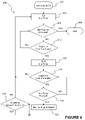
- FIG. 6 is a flow diagram similar to FIG. 4 depicting an alternative automatic shutdown adjustment system of the present disclosure.
- a work vehicle in the form of loader 10 is provided.
- the work vehicle may include any other type of work vehicle including a construction vehicle, such as a bulldozer, an excavator, or a motor grader, or an agricultural vehicle, such as a tractor, combine, or a harvester.
- Loader 10 includes articulated chassis 12 and ground engaging mechanism 14 .
- Ground engaging mechanism 14 may include any device capable of supporting and/or propelling chassis 12 .
- ground engaging mechanism 14 includes wheels.
- Ground engaging mechanism 14 may also include belts or steel tracks.
- Loader 10 also includes operator cab 16 supported by chassis 12 for an operator of loader 10 .
- Operator cab 16 includes a monitor (not shown) configured to communicate various messages to the user and receive inputs from the user.
- loader 10 further includes work tool 18 supported by chassis 12 .
- Work tool 18 may be forwardly mounted to chassis 12 and may include any device configured to move materials.
- work tool 18 may include a bucket, as shown in FIG. 1 , that scoops and dumps materials, such as dirt, sand, gravel, snow, salt, and other materials.
- Other work tools 18 such as blades, pallet forks, bail lifts, augers, harvesters, tillers, mowers, and other work tools may also be provided to move materials.
- Loader 10 may also include hydraulic components 20 configured to operate work tool 18 .
- loader 10 further includes engine 22 .
- Engine 22 is coupled to ground engaging mechanism 14 to power ground engaging mechanism 14 .
- engine 22 may be coupled to a transmission (not shown), and the transmission may in turn be coupled to ground engaging mechanism 14 to power ground engaging mechanism 14 .
- Loader 10 also includes engine control unit 24 configured to control the operation of engine 22 .
- loader 10 further includes system control unit 26 .
- System control unit 26 may be configured to communicate with various peripherals, such as throttle 28 , parking brake 30 , battery 32 , oil pump 34 , and/or ignition 36 .
- system control unit 26 may receive signals from a throttle position sensor (not shown) indicating the position of throttle 28 , which controls the supply of fuel to engine 22 .
- System control unit 26 may also be configured to communicate with engine control unit 24 or with engine 22 directly.
- system control unit 26 may be configured to monitor the speed of loader 10 across the ground.
- the present disclosure provides an idle function, which reduces the wear on engine 22 and the amount of fuel consumed by loader 10 .
- the idle function is configured to operate engine 22 in first idle state 40 for first period of time 42 and to operate engine 22 in second idle state 44 for second period of time 46 .
- Second period of time 46 occurs after first period of time 42 expires.
- engine 22 is running, but ground engaging mechanism 14 is not driven.
- Engine 22 operates at a lower speed in second idle state 44 than in first idle state 40 .
- the speed of engine 22 may drop by approximately 20% to 40% from first idle state 40 to second idle state 44 , and more specifically, the speed of engine 22 may drop from between approximately 900 and 950 rpm in first idle state 40 to between approximately 600 and 700 rpm in second idle state 44 .
- hydraulic components 20 may be disabled and engine 22 may shift to operate along a different torque curve.
- the idle function is configured to be modified by a user. From the monitor in operator cab 16 ( FIG. 1 ), the user may disable the idle function altogether. Also from the monitor, the user may set an idle timer to control the duration of first period of time 42 .
- the duration of first period of time 42 may be chosen from various provided increments, such as 5, 15, and 30 minute increments.
- the duration of the idle timer may be set to abide by site-specific and/or state-specific idling requirements.
- system control unit 26 may monitor the behavior of engine 22 itself and/or various peripherals. More specifically, system control unit 26 may monitor the behavior of engine 22 directly or via engine control unit 24 , throttle 28 , parking brake 30 , battery 32 , and/or oil pump 34 .
- system control unit 26 may determine that engine 22 is operating in first idle state 40 or second idle state 44 if one or more of the following conditions is satisfied: (1) engine 22 is operating at less than approximately 950 rpm; (2) engine 22 is operating at a load less than approximately 25%; (3) the position of throttle 28 is less than approximately 2.0%; (4) parking brake 30 is engaged; (5) ground speed is less than approximately 0.5 kph; (6) the voltage of battery 32 exceeds approximately 24V; and (7) the pressure at oil pump 34 is sufficient.
- System control unit 26 need not monitor the same peripherals to determine whether engine 22 is operating in first idle state 40 as it does to determine whether engine 22 is operating in second idle state 44 . For example, system control unit 26 may stop monitoring the load upon engine 22 when engine 22 begins to operate in second idle state 44 .
- An embodiment of the idle function is illustrated schematically as method 400 in FIG. 4 .
- engine 22 is turned on.
- the idle timer is set to control the duration of first period of time 42 .
- the idle timer may be set for 5, 15, or 30 minutes.
- system control unit 26 ensures that the idle function has not been disabled by the user. If the idle function has been disabled, method 400 ends at block 408 . If the idle function has not been disabled, method 400 continues to block 410 .
- system control unit 26 determines whether engine 22 is operating in first idle state 40 or in an active state.
- engine 22 will typically operate in the active state, not first idle state 40 , because engine 22 will be powering ground engaging mechanism 14 and/or hydraulic components 20 .
- the idle timer is initiated at block 412 to start measuring first period of time 42 .
- system control unit 26 ensures that engine 22 is operating in first idle state 40 until the idle timer expires at the end of first period of time 42 . If engine 22 begins to operate in the active state and ceases to operate in first idle state 40 before the idle timer expires, the idle timer is reset at block 404 .
- system control unit 26 determines whether engine 22 is operating in second idle state 44 . If engine 22 begins to operate in the active state and ceases to operate in second idle state 44 , the idle timer is reset at block 404 .
- the present disclosure further provides a shutdown function, which reduces the wear on engine 22 and the amount of fuel consumed by loader 10 .
- the shutdown function is configured to shutdown engine 22 after second period of time 46 , in which engine 22 operates in second idle state 44 , expires.
- Engine 22 may be shutdown by turning off power to ignition 36 of loader 10 , which has the same effect as shutting down loader 10 with a key.
- engine 22 may be shutdown by opening relay switch 50 between system control unit 26 and ignition 36 .
- the shutdown function is configured to be modified by a user. From the monitor in operator cab 16 ( FIG. 1 ), the user may disable the shutdown function altogether. The user may choose to disable the idle function along with the shutdown function, or the user may choose to disable the shutdown function without disabling the idle function. Also from the monitor, the user may set a shutdown timer to control the duration of second period of time 46 .
- the duration of second period of time 46 may be chosen from various provided increments, such as 5, 15, and 30 minute increments. The duration of the shutdown timer may be set to abide by site-specific and/or state-specific idling requirements.
- FIG. 5 An embodiment of the shutdown function is illustrated schematically as method 500 in FIG. 5 . Overlapping steps in method 400 ( FIG. 4 ) and method 500 are labeled with the same last two digits. Beginning with block 502 , engine 22 is turned on. At block 504 , the idle timer is set to control the duration of first period of time 42 , and the shutdown timer is set to control the duration of second period of time 46 . For example, the idle timer and the shutdown timer may each be set for 5, 15, or 30 minutes. Blocks corresponding to blocks 406 - 412 of method 400 have been omitted from FIG. 5 because they are similar to blocks 406 - 412 of method 400 .
- system control unit 26 ensures that engine 22 is operating in first idle state 40 until the idle timer expires at the end of first period of time 42 . If engine 22 begins to operate in the active state and ceases to operate in first idle state 40 before the idle timer expires, the idle timer is reset at block 504 . When the idle timer expires, system control unit 26 ensures at block 518 that shutdown function 38 has not been disabled by the user. If the idle function has not been disabled, the shutdown timer is initiated at block 520 to start measuring second period of time 46 , and then the speed of engine 22 is reduced at block 522 to operate in second idle state 44 .
- the shutdown timer is not initiated at block 520 before reducing the speed of engine 22 at block 522 .
- system control unit 26 ensures that engine 22 is operating in second idle state 44 until the shutdown timer expires at the end of second period of time 46 . If engine 22 begins to operate in the active state and ceases to operate in second idle state 44 before the shutdown timer expires, the idle timer and the shutdown timer are reset at block 504 . If the shutdown timer expires, engine 22 is shutdown at block 532 .
- FIG. 6 Another embodiment of the shutdown function is illustrated schematically as method 600 in FIG. 6 . Overlapping steps in method 400 ( FIG. 4 ), method 500 ( FIG. 5 ), and method 600 are labeled with the same last two digits. Like method 500 , between blocks 624 and 630 , system control unit 26 ensures that engine 22 is operating in second idle state 44 until the shutdown timer expires at the end of second period of time 46 . Unlike method 500 , method 600 includes blocks 626 and 628 between blocks 624 and 630 . When the shutdown timer is nearing expiration, an alarm is operated at block 628 . For example, when the shutdown timer is within 30 seconds of expiration, an audible alarm may sound and a message may appear on the monitor in operator cab 16 ( FIG.
- the audible alarm may include a series of clicks that becomes more frequent as the shutdown timer approaches expiration. Similarly, the audible alarm may increase in pitch or volume as the shutdown timer approaches expiration.
- the idle timer and the shutdown timer are reset at block 604 . If the shutdown timer expires, engine 22 is shutdown at block 632 .
Landscapes
- Engineering & Computer Science (AREA)
- General Engineering & Computer Science (AREA)
- Chemical & Material Sciences (AREA)
- Combustion & Propulsion (AREA)
- Mechanical Engineering (AREA)
- Mining & Mineral Resources (AREA)
- Civil Engineering (AREA)
- Structural Engineering (AREA)
- Control Of Vehicle Engines Or Engines For Specific Uses (AREA)
- Operation Control Of Excavators (AREA)
- Electrical Control Of Air Or Fuel Supplied To Internal-Combustion Engine (AREA)
Abstract
Description
Claims (23)
Priority Applications (6)
| Application Number | Priority Date | Filing Date | Title |
|---|---|---|---|
| US12/059,750 US7702450B2 (en) | 2008-03-11 | 2008-03-31 | Automatic idle adjustment and shutdown of vehicle |
| CA2630076A CA2630076C (en) | 2008-03-11 | 2008-04-30 | Automatic idle adjustment and shutdown of vehicle |
| BRPI0900627-3A BRPI0900627B1 (en) | 2008-03-11 | 2009-02-26 | working vehicle, and, method for automatically adjusting the speed of a working vehicle engine |
| MX2009002264A MX2009002264A (en) | 2008-03-11 | 2009-02-27 | Automatic idle adjustment and shutdown of vehicle. |
| EP09153914A EP2101054B1 (en) | 2008-03-11 | 2009-02-27 | Work Vehicle and Method for Automatically Adjusting a Speed of an Engine of the Work Vehicle |
| CN200910119985.9A CN101531191B (en) | 2008-03-11 | 2009-03-02 | Automatic idle adjustment and shutdown of vehicle |
Applications Claiming Priority (2)
| Application Number | Priority Date | Filing Date | Title |
|---|---|---|---|
| US3563308P | 2008-03-11 | 2008-03-11 | |
| US12/059,750 US7702450B2 (en) | 2008-03-11 | 2008-03-31 | Automatic idle adjustment and shutdown of vehicle |
Publications (2)
| Publication Number | Publication Date |
|---|---|
| US20090234563A1 US20090234563A1 (en) | 2009-09-17 |
| US7702450B2 true US7702450B2 (en) | 2010-04-20 |
Family
ID=40672255
Family Applications (1)
| Application Number | Title | Priority Date | Filing Date |
|---|---|---|---|
| US12/059,750 Active 2028-05-01 US7702450B2 (en) | 2008-03-11 | 2008-03-31 | Automatic idle adjustment and shutdown of vehicle |
Country Status (6)
| Country | Link |
|---|---|
| US (1) | US7702450B2 (en) |
| EP (1) | EP2101054B1 (en) |
| CN (1) | CN101531191B (en) |
| BR (1) | BRPI0900627B1 (en) |
| CA (1) | CA2630076C (en) |
| MX (1) | MX2009002264A (en) |
Cited By (15)
| Publication number | Priority date | Publication date | Assignee | Title |
|---|---|---|---|---|
| US20100331142A1 (en) * | 2008-01-31 | 2010-12-30 | Isuzu Motors Limited | Pto control device |
| US20110131074A1 (en) * | 2009-09-24 | 2011-06-02 | David S Gilleland | Maintenance control system |
| US20130079999A1 (en) * | 2011-09-28 | 2013-03-28 | Caterpillar Paving Products Inc. | Rotor/Engine Speed Control for Cold Planer |
| US20130333664A1 (en) * | 2012-06-15 | 2013-12-19 | Caterpillar Paving Products | Engine Speed Management Control System for Cold Planers |
| WO2014120935A3 (en) * | 2013-01-30 | 2014-10-02 | Bombardier Recreational Products Inc. | Methods and system for operation of a vehicle |
| US20150039187A1 (en) * | 2013-08-05 | 2015-02-05 | Deere & Company | System and method for controlling a drive unit of a work machine during an idle state |
| US20160160829A1 (en) * | 2014-12-04 | 2016-06-09 | Hyundai Motor Company | Method for preventing engine stall of vehicle |
| US9706709B2 (en) | 2015-09-10 | 2017-07-18 | Deere & Company | Harvester fan speed control based on yield |
| US9759147B2 (en) | 2014-08-29 | 2017-09-12 | Cnh Industrial America Llc | Idle return system and method for an off highway vehicle |
| RU2636249C2 (en) * | 2012-06-29 | 2017-11-21 | Бомбардье Рекриэйшенел Продактс Инк. | System and method to control vehicle |
| US10059328B2 (en) | 2016-08-11 | 2018-08-28 | Ford Global Technologies, Llc | System and method to control battery current during rolling stop-start events |
| US10266134B2 (en) * | 2017-06-02 | 2019-04-23 | Ford Global Technologies, Llc | Vehicle accessory power management |
| US10907326B2 (en) | 2017-08-11 | 2021-02-02 | Deere & Company | Vision system for monitoring a work tool of a work vehicle |
| US20210315162A1 (en) * | 2020-04-14 | 2021-10-14 | Kanzaki Kokyukoki Mfg. Co., Ltd. | Control system of lawn mowing vehicle |
| US20250243821A1 (en) * | 2024-01-26 | 2025-07-31 | Ford Global Technologies, Llc | System and method for power take-off control |
Families Citing this family (8)
| Publication number | Priority date | Publication date | Assignee | Title |
|---|---|---|---|---|
| DE102010041115A1 (en) * | 2010-09-21 | 2012-03-22 | Siemens Aktiengesellschaft | Locomotive with main and auxiliary power supply and an automated start / stop operation |
| GB201111291D0 (en) * | 2011-06-30 | 2011-08-17 | Agco Int Gmbh | Engine control system |
| WO2014160041A1 (en) | 2013-03-13 | 2014-10-02 | Husqvarna Ab | Riding lawn care vehicle auto idle system |
| US10037634B2 (en) * | 2016-03-22 | 2018-07-31 | Deere & Company | System and method for idle state determination |
| KR20190081099A (en) * | 2017-12-29 | 2019-07-09 | 주식회사 두산 | Engine control system and method for industrial vehicle |
| CN114251181B (en) * | 2020-09-22 | 2024-01-19 | 北京福田康明斯发动机有限公司 | Engine idle speed optimization control method and device and vehicle |
| CN112555032B (en) * | 2020-12-08 | 2022-08-05 | 广西柳工机械股份有限公司 | Engine active throttle shovel loading control method and loader |
| US20250153722A1 (en) * | 2023-11-13 | 2025-05-15 | GM Global Technology Operations LLC | Protected idle system for a vehicle |
Citations (32)
| Publication number | Priority date | Publication date | Assignee | Title |
|---|---|---|---|---|
| US4457392A (en) | 1980-08-08 | 1984-07-03 | Associated Engineering Limited | Automatic speed control systems |
| US4534466A (en) | 1982-05-24 | 1985-08-13 | Republic Steel Corporation | Nestable container for parts storage |
| US4562808A (en) | 1983-09-27 | 1986-01-07 | Mazda Motor Corporation | Engine idling speed control |
| US4590906A (en) | 1983-12-29 | 1986-05-27 | Isuzu Motors, Ltd. | Fuel control mechanism in internal combustion engine |
| US4597047A (en) | 1984-07-13 | 1986-06-24 | Motorola, Inc. | Engine control system including engine idle speed control |
| US4660519A (en) | 1984-07-13 | 1987-04-28 | Motorola, Inc. | Engine control system |
| US4697562A (en) | 1983-02-25 | 1987-10-06 | Regie Nationale Des Usines Renault | Process and device for regulating the rotation speed in neutral of a controlled ignition engine equipped with intermittently functioning accessories |
| US4841447A (en) | 1985-05-22 | 1989-06-20 | Toyota Jidosha Kabushiki Kaisha | System for controlling idling speed in internal combustion engine for vehicle with automatic transmission |
| US4977878A (en) | 1988-10-28 | 1990-12-18 | Hubbard Jr Larry M | Carburetor idler assist system |
| US5005546A (en) | 1988-12-22 | 1991-04-09 | Vdo Adolf Schindling Ag | Setting device for a feed device of an internal combustion engine |
| US5014666A (en) | 1989-08-16 | 1991-05-14 | Vdo Adolf Schindling Ag | Load adjustment device |
| US5040507A (en) | 1990-03-07 | 1991-08-20 | Cummins Engine Company, Inc. | Method and device for variable idle speed control of an internal combustion engine |
| US5480364A (en) | 1994-08-15 | 1996-01-02 | Caterpillar Inc. | Elevated idle speed control and method of operating same |
| US5528500A (en) | 1994-02-18 | 1996-06-18 | Caterpillar Inc. | Programmable high idle set switch and method of operating same |
| US5611751A (en) | 1995-09-26 | 1997-03-18 | Caterpillar Inc. | Engine speed control and method for operating same |
| US6019702A (en) | 1998-05-14 | 2000-02-01 | Caterpillar Inc. | Automatic elevated idle speed control and method of operating same |
| US6021755A (en) | 1998-07-23 | 2000-02-08 | Caterpillar Inc. | Method and apparatus for determining a fuel command for a fuel system |
| US6060981A (en) * | 1999-04-23 | 2000-05-09 | Caterpillar Inc. | Vehicle security system for unattended idle operations |
| US6092504A (en) | 1998-08-04 | 2000-07-25 | Caterpillar Inc. | Device for controlling engine speed using dual governors |
| US6173696B1 (en) | 1998-12-17 | 2001-01-16 | Daimlerchrysler Corporation | Virtual power steering switch |
| US6182634B1 (en) | 1999-10-13 | 2001-02-06 | Caterpillar Inc. | Low RPM switching tachometer |
| US6338697B1 (en) | 1997-08-01 | 2002-01-15 | Renault Agriculture | Method for controlling an internal combustion engine |
| US6363906B1 (en) * | 2000-03-06 | 2002-04-02 | Detroit Diesel Corporation | Idle shutdown override with defeat protection |
| US6366848B1 (en) * | 2000-09-19 | 2002-04-02 | Volvo Trucks North America, Inc. | Engine control system for providing incentive to drivers |
| US6421589B1 (en) | 1996-07-12 | 2002-07-16 | Robert Bosch Gmbh | Method and arrangement for detecting a changing quantity for motor vehicles |
| US6530426B1 (en) | 1999-04-15 | 2003-03-11 | Denso Corporation | Motor drive-control device |
| US6817338B2 (en) | 2002-02-04 | 2004-11-16 | Cummins, Inc. | Idle speed control system |
| US6845751B2 (en) | 2002-05-09 | 2005-01-25 | Hyundai Motor Company | Method and apparatus for controlling idle speed of an engine |
| US7040269B2 (en) | 2000-08-28 | 2006-05-09 | Siemens Aktiengesellschaft | Method for operating a drive with an internal combustion engine and an electric machine |
| US7104924B2 (en) | 2004-09-20 | 2006-09-12 | Detroit Diesel Corporation | System and method for controlling engine idle speed based on operational state settings |
| US7310576B1 (en) * | 2006-06-07 | 2007-12-18 | Detroit Diesel Corporation | Method and system to control internal combustion engine idle shut down |
| US7377103B2 (en) | 2005-07-07 | 2008-05-27 | Ford Global Technologies, Llc | System and method for controlling an engine having a power take off output device |
Family Cites Families (6)
| Publication number | Priority date | Publication date | Assignee | Title |
|---|---|---|---|---|
| US638697A (en) * | 1898-12-19 | 1899-12-12 | George W Bolser | Trolley. |
| DE3560243D1 (en) * | 1984-03-30 | 1987-07-16 | Komatsu Mfg Co Ltd | Method and system for controlling an engine |
| US5219413A (en) | 1991-09-11 | 1993-06-15 | Carolina Tractor | Engine idle shut-down controller |
| US6274944B1 (en) * | 2000-01-06 | 2001-08-14 | Detroit Diesel Corporation | Method for engine control |
| US6694240B1 (en) | 2002-08-29 | 2004-02-17 | Caterpillar Inc | Control system for and method of operating a work machine |
| US7165530B2 (en) | 2005-06-01 | 2007-01-23 | Caterpillar Inc | Method for controlling a variable-speed engine |
-
2008
- 2008-03-31 US US12/059,750 patent/US7702450B2/en active Active
- 2008-04-30 CA CA2630076A patent/CA2630076C/en active Active
-
2009
- 2009-02-26 BR BRPI0900627-3A patent/BRPI0900627B1/en active IP Right Grant
- 2009-02-27 MX MX2009002264A patent/MX2009002264A/en active IP Right Grant
- 2009-02-27 EP EP09153914A patent/EP2101054B1/en active Active
- 2009-03-02 CN CN200910119985.9A patent/CN101531191B/en active Active
Patent Citations (32)
| Publication number | Priority date | Publication date | Assignee | Title |
|---|---|---|---|---|
| US4457392A (en) | 1980-08-08 | 1984-07-03 | Associated Engineering Limited | Automatic speed control systems |
| US4534466A (en) | 1982-05-24 | 1985-08-13 | Republic Steel Corporation | Nestable container for parts storage |
| US4697562A (en) | 1983-02-25 | 1987-10-06 | Regie Nationale Des Usines Renault | Process and device for regulating the rotation speed in neutral of a controlled ignition engine equipped with intermittently functioning accessories |
| US4562808A (en) | 1983-09-27 | 1986-01-07 | Mazda Motor Corporation | Engine idling speed control |
| US4590906A (en) | 1983-12-29 | 1986-05-27 | Isuzu Motors, Ltd. | Fuel control mechanism in internal combustion engine |
| US4660519A (en) | 1984-07-13 | 1987-04-28 | Motorola, Inc. | Engine control system |
| US4597047A (en) | 1984-07-13 | 1986-06-24 | Motorola, Inc. | Engine control system including engine idle speed control |
| US4841447A (en) | 1985-05-22 | 1989-06-20 | Toyota Jidosha Kabushiki Kaisha | System for controlling idling speed in internal combustion engine for vehicle with automatic transmission |
| US4977878A (en) | 1988-10-28 | 1990-12-18 | Hubbard Jr Larry M | Carburetor idler assist system |
| US5005546A (en) | 1988-12-22 | 1991-04-09 | Vdo Adolf Schindling Ag | Setting device for a feed device of an internal combustion engine |
| US5014666A (en) | 1989-08-16 | 1991-05-14 | Vdo Adolf Schindling Ag | Load adjustment device |
| US5040507A (en) | 1990-03-07 | 1991-08-20 | Cummins Engine Company, Inc. | Method and device for variable idle speed control of an internal combustion engine |
| US5528500A (en) | 1994-02-18 | 1996-06-18 | Caterpillar Inc. | Programmable high idle set switch and method of operating same |
| US5480364A (en) | 1994-08-15 | 1996-01-02 | Caterpillar Inc. | Elevated idle speed control and method of operating same |
| US5611751A (en) | 1995-09-26 | 1997-03-18 | Caterpillar Inc. | Engine speed control and method for operating same |
| US6421589B1 (en) | 1996-07-12 | 2002-07-16 | Robert Bosch Gmbh | Method and arrangement for detecting a changing quantity for motor vehicles |
| US6338697B1 (en) | 1997-08-01 | 2002-01-15 | Renault Agriculture | Method for controlling an internal combustion engine |
| US6019702A (en) | 1998-05-14 | 2000-02-01 | Caterpillar Inc. | Automatic elevated idle speed control and method of operating same |
| US6021755A (en) | 1998-07-23 | 2000-02-08 | Caterpillar Inc. | Method and apparatus for determining a fuel command for a fuel system |
| US6092504A (en) | 1998-08-04 | 2000-07-25 | Caterpillar Inc. | Device for controlling engine speed using dual governors |
| US6173696B1 (en) | 1998-12-17 | 2001-01-16 | Daimlerchrysler Corporation | Virtual power steering switch |
| US6530426B1 (en) | 1999-04-15 | 2003-03-11 | Denso Corporation | Motor drive-control device |
| US6060981A (en) * | 1999-04-23 | 2000-05-09 | Caterpillar Inc. | Vehicle security system for unattended idle operations |
| US6182634B1 (en) | 1999-10-13 | 2001-02-06 | Caterpillar Inc. | Low RPM switching tachometer |
| US6363906B1 (en) * | 2000-03-06 | 2002-04-02 | Detroit Diesel Corporation | Idle shutdown override with defeat protection |
| US7040269B2 (en) | 2000-08-28 | 2006-05-09 | Siemens Aktiengesellschaft | Method for operating a drive with an internal combustion engine and an electric machine |
| US6366848B1 (en) * | 2000-09-19 | 2002-04-02 | Volvo Trucks North America, Inc. | Engine control system for providing incentive to drivers |
| US6817338B2 (en) | 2002-02-04 | 2004-11-16 | Cummins, Inc. | Idle speed control system |
| US6845751B2 (en) | 2002-05-09 | 2005-01-25 | Hyundai Motor Company | Method and apparatus for controlling idle speed of an engine |
| US7104924B2 (en) | 2004-09-20 | 2006-09-12 | Detroit Diesel Corporation | System and method for controlling engine idle speed based on operational state settings |
| US7377103B2 (en) | 2005-07-07 | 2008-05-27 | Ford Global Technologies, Llc | System and method for controlling an engine having a power take off output device |
| US7310576B1 (en) * | 2006-06-07 | 2007-12-18 | Detroit Diesel Corporation | Method and system to control internal combustion engine idle shut down |
Non-Patent Citations (2)
| Title |
|---|
| "Caterpillar Celebrates Track-Type Tractor 100th Anniversary", Dec. 2004, 12 pg. |
| "Muirhead Protection Systems -Excess Idle Shutdown ", Dec. 4, 2005, 1 pg., Remote Control Technologies, also available at www.rct.net.au. |
Cited By (22)
| Publication number | Priority date | Publication date | Assignee | Title |
|---|---|---|---|---|
| US8435158B2 (en) * | 2008-01-31 | 2013-05-07 | Isuzu Motors Limited | PTO control device |
| US20100331142A1 (en) * | 2008-01-31 | 2010-12-30 | Isuzu Motors Limited | Pto control device |
| US20110131074A1 (en) * | 2009-09-24 | 2011-06-02 | David S Gilleland | Maintenance control system |
| US20110130893A1 (en) * | 2009-09-24 | 2011-06-02 | Gilleland David S | Energy management system |
| US20130079999A1 (en) * | 2011-09-28 | 2013-03-28 | Caterpillar Paving Products Inc. | Rotor/Engine Speed Control for Cold Planer |
| US9267446B2 (en) * | 2012-06-15 | 2016-02-23 | Caterpillar Paving Products Inc. | Engine speed management control system for cold planers |
| US20130333664A1 (en) * | 2012-06-15 | 2013-12-19 | Caterpillar Paving Products | Engine Speed Management Control System for Cold Planers |
| RU2636249C2 (en) * | 2012-06-29 | 2017-11-21 | Бомбардье Рекриэйшенел Продактс Инк. | System and method to control vehicle |
| US9481370B2 (en) | 2013-01-30 | 2016-11-01 | Bombardier Recreational Products Inc. | Methods and system for operation of vehicle |
| RU2660235C2 (en) * | 2013-01-30 | 2018-07-05 | Бомбардье Рекриэйшенел Продактс Инк. | Vehicle operation method (embodiments) |
| WO2014120935A3 (en) * | 2013-01-30 | 2014-10-02 | Bombardier Recreational Products Inc. | Methods and system for operation of a vehicle |
| US20150039187A1 (en) * | 2013-08-05 | 2015-02-05 | Deere & Company | System and method for controlling a drive unit of a work machine during an idle state |
| US9644345B2 (en) * | 2013-08-05 | 2017-05-09 | Deere & Company | System and method for controlling a drive unit of a work machine during an idle state |
| US9759147B2 (en) | 2014-08-29 | 2017-09-12 | Cnh Industrial America Llc | Idle return system and method for an off highway vehicle |
| US20160160829A1 (en) * | 2014-12-04 | 2016-06-09 | Hyundai Motor Company | Method for preventing engine stall of vehicle |
| US9706709B2 (en) | 2015-09-10 | 2017-07-18 | Deere & Company | Harvester fan speed control based on yield |
| US10059328B2 (en) | 2016-08-11 | 2018-08-28 | Ford Global Technologies, Llc | System and method to control battery current during rolling stop-start events |
| US10266134B2 (en) * | 2017-06-02 | 2019-04-23 | Ford Global Technologies, Llc | Vehicle accessory power management |
| US10907326B2 (en) | 2017-08-11 | 2021-02-02 | Deere & Company | Vision system for monitoring a work tool of a work vehicle |
| US20210315162A1 (en) * | 2020-04-14 | 2021-10-14 | Kanzaki Kokyukoki Mfg. Co., Ltd. | Control system of lawn mowing vehicle |
| US20250243821A1 (en) * | 2024-01-26 | 2025-07-31 | Ford Global Technologies, Llc | System and method for power take-off control |
| US12540585B2 (en) * | 2024-01-26 | 2026-02-03 | Ford Global Technologies, Llc | System and method for power take-off control |
Also Published As
| Publication number | Publication date |
|---|---|
| US20090234563A1 (en) | 2009-09-17 |
| EP2101054A2 (en) | 2009-09-16 |
| EP2101054B1 (en) | 2012-12-19 |
| BRPI0900627B1 (en) | 2021-02-09 |
| CA2630076C (en) | 2015-11-03 |
| BRPI0900627A2 (en) | 2010-01-19 |
| EP2101054A3 (en) | 2011-06-15 |
| CN101531191A (en) | 2009-09-16 |
| CN101531191B (en) | 2014-04-09 |
| MX2009002264A (en) | 2009-09-23 |
| CA2630076A1 (en) | 2009-09-11 |
Similar Documents
| Publication | Publication Date | Title |
|---|---|---|
| US7702450B2 (en) | Automatic idle adjustment and shutdown of vehicle | |
| EP2022954B1 (en) | Exhaust gas purifier of construction machine | |
| US9010094B2 (en) | Engine control system and method for initiating a diesel particulate filter regeneration | |
| US8335618B2 (en) | Automatic shut down system for machine having engine and work implement | |
| US20150039187A1 (en) | System and method for controlling a drive unit of a work machine during an idle state | |
| CN104723875B (en) | Vehicle with a steering wheel | |
| US9037358B2 (en) | Wheel loader | |
| US9523315B2 (en) | Engine control device for work vehicle | |
| US20120151905A1 (en) | Control Apparatus and Method for a Hydrostatically Actuated Vehicle | |
| EP2700799B1 (en) | Wheel loader | |
| JP2003343325A (en) | Work vehicle | |
| US7908068B2 (en) | Engine controller of hydraulic shovel | |
| WO1989011590A1 (en) | Adaptive engine output mode setting method based on shoe slip | |
| JP4875663B2 (en) | Accelerator control structure of work vehicle | |
| WO2014198065A1 (en) | Engine power boost system and method | |
| CN106574457A (en) | Working machine display device | |
| JP4972610B2 (en) | Accelerator control structure of work vehicle | |
| EP2851540B1 (en) | Anti-lug and anti-stall control unit | |
| JP5292926B2 (en) | Work vehicle | |
| US9216741B2 (en) | Lock up clutch controls—high idle set point | |
| JP2010174769A (en) | Working vehicle | |
| JPH094481A (en) | Engine output control device for traveling work machine | |
| JP2008157140A (en) | Work vehicle | |
| JPH0925838A (en) | Engine output control device for traveling work machine | |
| JP5274168B2 (en) | Farm tractor |
Legal Events
| Date | Code | Title | Description |
|---|---|---|---|
| AS | Assignment |
Owner name: DEERE & COMPANY, ILLINOIS Free format text: ASSIGNMENT OF ASSIGNORS INTEREST;ASSIGNORS:PFOHL, KEVIN LEE;CAMPBELL, KEVIN W.;OFTEDAL, TERYL MARVIN;REEL/FRAME:020781/0757;SIGNING DATES FROM 20080331 TO 20080404 Owner name: DEERE & COMPANY,ILLINOIS Free format text: ASSIGNMENT OF ASSIGNORS INTEREST;ASSIGNORS:PFOHL, KEVIN LEE;CAMPBELL, KEVIN W.;OFTEDAL, TERYL MARVIN;SIGNING DATES FROM 20080331 TO 20080404;REEL/FRAME:020781/0757 |
|
| STCF | Information on status: patent grant |
Free format text: PATENTED CASE |
|
| FPAY | Fee payment |
Year of fee payment: 4 |
|
| MAFP | Maintenance fee payment |
Free format text: PAYMENT OF MAINTENANCE FEE, 8TH YEAR, LARGE ENTITY (ORIGINAL EVENT CODE: M1552) Year of fee payment: 8 |
|
| MAFP | Maintenance fee payment |
Free format text: PAYMENT OF MAINTENANCE FEE, 12TH YEAR, LARGE ENTITY (ORIGINAL EVENT CODE: M1553); ENTITY STATUS OF PATENT OWNER: LARGE ENTITY Year of fee payment: 12 |