US7697743B2 - Methods and systems for prescribing parameters for tomosynthesis - Google Patents
Methods and systems for prescribing parameters for tomosynthesis Download PDFInfo
- Publication number
- US7697743B2 US7697743B2 US11/500,680 US50068006A US7697743B2 US 7697743 B2 US7697743 B2 US 7697743B2 US 50068006 A US50068006 A US 50068006A US 7697743 B2 US7697743 B2 US 7697743B2
- Authority
- US
- United States
- Prior art keywords
- image
- detector
- slice
- thickness
- tomosynthesis
- Prior art date
- Legal status (The legal status is an assumption and is not a legal conclusion. Google has not performed a legal analysis and makes no representation as to the accuracy of the status listed.)
- Expired - Lifetime, expires
Links
Images


Classifications
-
- G—PHYSICS
- G06—COMPUTING OR CALCULATING; COUNTING
- G06T—IMAGE DATA PROCESSING OR GENERATION, IN GENERAL
- G06T12/00—Tomographic reconstruction from projections
- G06T12/10—Image preprocessing, e.g. calibration, positioning of sources or scatter correction
-
- G—PHYSICS
- G06—COMPUTING OR CALCULATING; COUNTING
- G06T—IMAGE DATA PROCESSING OR GENERATION, IN GENERAL
- G06T12/00—Tomographic reconstruction from projections
- G06T12/30—Image post-processing, e.g. metal artefact correction
-
- G—PHYSICS
- G06—COMPUTING OR CALCULATING; COUNTING
- G06T—IMAGE DATA PROCESSING OR GENERATION, IN GENERAL
- G06T2207/00—Indexing scheme for image analysis or image enhancement
- G06T2207/10—Image acquisition modality
- G06T2207/10072—Tomographic images
- G06T2207/10112—Digital tomosynthesis [DTS]
-
- G—PHYSICS
- G06—COMPUTING OR CALCULATING; COUNTING
- G06T—IMAGE DATA PROCESSING OR GENERATION, IN GENERAL
- G06T2207/00—Indexing scheme for image analysis or image enhancement
- G06T2207/30—Subject of image; Context of image processing
- G06T2207/30004—Biomedical image processing
-
- G—PHYSICS
- G06—COMPUTING OR CALCULATING; COUNTING
- G06T—IMAGE DATA PROCESSING OR GENERATION, IN GENERAL
- G06T2211/00—Image generation
- G06T2211/40—Computed tomography
- G06T2211/436—Limited angle
-
- G—PHYSICS
- G06—COMPUTING OR CALCULATING; COUNTING
- G06V—IMAGE OR VIDEO RECOGNITION OR UNDERSTANDING
- G06V2201/00—Indexing scheme relating to image or video recognition or understanding
- G06V2201/03—Recognition of patterns in medical or anatomical images
Definitions
- Embodiments of the present application relate generally to prescribing parameters for tomosynthesis. Particularly, certain embodiments relate to prescribing parameters based on an interaction with a localization image.
- Digital tomosynthesis imaging is a technique that requires the acquisition of multiple x-ray images at different angles relative to the patient within a relatively short time interval. Once these images have been acquired, a reconstruction algorithm is applied to the data represented by the images to reconstruct “slices” through the patient. These slices, which are essentially re-constructed x-ray images of selected planes within an object or patient, may eliminate any structures underlying or overlying a particular area or region of interest and thereby allow for improved diagnosis and treatment.
- Yet another potential problem is that the use of large angulation ranges may result in increased scatter when no grid is used. Furthermore, errors and uncertainty in the positioning of the source and the detector may result in image reconstruction artifacts. Still another potential problem is that the reduced exposure used in tomosynthesis (relative to the standard single acquisition) may result in increased noise being present in the resulting images.
- Certain embodiments of the present invention provide a method for performing tomosynthesis including: receiving an image representative of an anatomy of a patient; allowing an interaction with the image to arrange at least one element with respect to the image to form an arrangement; and prescribing at least one parameter for obtaining a tomosynthesis image based at least in part on the arrangement.
- the method further includes performing tomosynthesis in accordance with the at least one parameter.
- the at least one element includes a detector representation.
- the at least one element includes at least one thickness guide.
- the at least one element includes at least one slice location guide.
- the at least one parameter includes at least one of: a detector position, a detector size, a thickness size, a thickness position, a slice size, a slice position, a slice thickness, a slice separation, a field of view, a reconstruction algorithm, a hanging protocol, and an image processing routine.
- the at least one parameter includes at least one of: an x-ray source location, an x-ray source angulation, an x-ray beam intensity, an x-ray beam gating, and a detector sensitivity.
- the interaction is performed at least in part automatically.
- the tomosynthesis is performed at least in part automatically.
- Certain embodiments of the present invention provide a system for performing tomosynthesis including: a user interface configured to allow a user to interact with a processor; and an application capable of running on the computer, wherein the application is capable of receiving an image representative of a patient; wherein the user may interact with the application through the user interface to arrange at least one element with respect to the image to generate at least one parameter for performing tomosynthesis.
- the at least one element includes at least one of: a detector representation, at least one thickness guide, a field of view guide, and at least one slice location guide.
- the at least one parameter includes at least one of: a detector position, a detector size, a thickness size, a thickness position, a slice size, a slice position, a slice thickness, a slice separation, a field of view, a reconstruction algorithm, a hanging protocol, and an image processing routine.
- the at least one parameter includes at least one of: an x-ray source location, an x-ray source angulation, an x-ray beam intensity, an x-ray beam gating, and a detector sensitivity.
- the application is capable of automatically arranging the at least one element.
- the system further includes a tomosynthesis system communicatively linked to the computer for acquiring at least one tomosynthesis image, the tomosynthesis system including an x-ray source having a position and an angulation, and an x-ray detector.
- Certain embodiments of the present invention provide a computer-readable storage medium including a set of instructions for execution on a computer, the set of instructions including: a reception routine for receiving an image representative of an anatomy of a patient along a dimension; an interaction routine for allowing an interaction with the image to arrange at least one element with respect to the image to form an arrangement; and a prescription routine for prescribing at least one parameter for obtaining a tomosynthesis image based at least in part on the arrangement.
- the set of instructions further includes a tomosynthesis routine for performing tomosynthesis in accordance with the at least one parameter.
- the at least one element includes at least one of: a detector representation, at least one thickness guide, a field of view guide, and at least one slice location guide.
- the at least one parameter includes at least one of: a detector position, a detector size, a thickness size, a thickness position, a slice size, a slice position, a slice thickness, a slice separation, a field of view, a reconstruction algorithm, a hanging protocol, and an image processing routine.
- the at least one parameter includes at least one of: an x-ray source location, an x-ray source angulation, an x-ray beam intensity, an x-ray beam gating, and a detector sensitivity.
- FIG. 1 is a schematic diagram of a tomosynthesis system according to one embodiment of the invention.
- FIG. 2 is a flowchart showing the steps in a tomosynthesis imaging chain according to a preferred embodiment.
- FIG. 3 is a flowchart showing the first step illustrated in the tomosynthesis imaging chain of FIG. 2 .
- FIG. 4 is a flowchart showing the second step illustrated in the tomosynthesis imaging chain imaging chain of FIG. 2 .
- FIG. 5 is a flowchart showing the third step illustrated in the tomosynthesis imaging chain imaging chain of FIG. 2 .
- FIG. 6 is a flowchart showing the fourth step illustrated in the tomosynthesis imaging chain imaging chain of FIG. 2 .
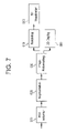
- FIG. 7 is a flowchart showing the fifth step illustrated in the tomosynthesis imaging chain imaging chain of FIG. 2 .
- FIG. 8 shows a series of images illustrative of localizer acquisition, in accordance with an embodiment of the present invention.
- FIG. 9 shows a flowchart of a method for performing localization for tomosynthesis, in accordance with an embodiment of the present invention.
- Tomosynthesis system 10 includes an x-ray source 20 , a detector 30 , a computer 40 , and supporting structure 50 .
- X-ray source 20 is directed toward a subject 21 (e.g., object, patient, etc.) and is configured to emit a beam of x-rays 22 at desired times. Once x-rays 22 are emitted, they pass through subject 21 and are picked up by, or hit, detector 30 .
- subject 21 e.g., object, patient, etc.
- Detector 30 may be any one of a variety of different detectors conventionally known within the art or that will become available in the future (e.g., energy discriminating detectors that are theoretically capable of acquiring high and low energy images simultaneously).
- detector 30 is a flat panel digital detector.
- x-rays 22 are picked up by detector 30 , they are converted into electrical signals that are sent to computer 40 .
- the electrical signals will vary depending on a number of factors, including the angle at which x-rays 22 hit detector 30 , the intensity of the different x-rays that hit detector 30 , and a number of other factors. Based on these electrical signals, computer 40 is then capable of creating an image of the internal structures of subject 21 .
- Computer 40 (e.g., processor, controller, etc.) includes processing circuitry that executes stored program logic and may be any one of a variety of different computers, processors, or controllers (or combination thereof) that are available for and compatible with the various types of equipment and devices used in tomosynthesis system 10 . Through its various processors and controllers computer 40 controls the operation and function of source 20 and detector 30 . For example, computer 40 may control, among other functions and operations, when source 20 emits x-rays, how detector 30 reads and conveys information or signals after the x-rays hit detector 30 , and how source 20 and detector 30 move relative to one another and relative to subject 21 . Computer 40 also controls how information (e.g. images or data acquired during the tomosynthesis operation) is processed and displayed.
- information e.g. images or data acquired during the tomosynthesis operation
- Computer 40 The different processing steps performed by computer 40 are dictated and controlled by software designed to allow computer 40 to perform the various operations underlying tomosynthesis. Information may also be stored in computer 40 for later retrieval and use. Computer 40 may further have a user interface for allowing a user to interact with an application executing on the computer.
- any one or more of source 20 , detector 30 , and subject 21 may move relative to one or more of the others while the images are being acquired. This motion may take place at the same time the images are being acquired or in-between the different image acquisitions.
- the movement of source 20 , detector 30 , and/or subject 21 (which may be accomplished through a movable table or support structure, which is not shown) are generally controlled by computer 40 based on information entered into computer 40 by someone operating the tomosynthesis equipment, based on pre-defined acquisition protocols, or based on information that has already been acquired by computer 40 .
- Imaging chain 100 that is utilized in the tomosynthesis process is shown according to a preferred embodiment.
- Imaging chain 100 includes steps 200 , 300 , 400 , 500 , 600 , 700 , and 800 .
- step 200 the patient is prepared for the tomosynthesis process and the x-ray images are acquired.
- step 200 can be broken down into sub-steps 210 , 220 , 230 , 240 , 250 , and 260 .
- the patient and x-ray equipment are prepared for the acquisition of x-ray images. This preparation includes generally determining where the x-rays will be focused, placing the patient in the appropriate location, and preparing the x-ray equipment to take images or acquisitions in the desired region of the patient.
- a “pre-tomosynthesis” image or acquisition is acquired in order to get information relating to patient positioning, patient characteristics, and/or acquisition characteristics or parameters.
- a “pre-tomosynthesis” image or acquisition e.g. a localizer acquisition
- any projection image acquired during a tomosynthesis sequence may be usable and/or acquirable for the pre-tomosynthesis image.
- the image may provide information such as body thickness and general anatomy and may additionally help with the location and identification of any implantable devices or non-standard structures (e.g. a missing lung, an enlarged heart, etc.).
- This information, along with other information the pre-tomosynthesis image may provide, may be used by computer 40 , or by the operator in a semi-automatic mode, as a basis for optimizing the parameters or characteristics of subsequent acquisitions.
- the information provided by the pre-tomosynthesis image may be used as a basis for optimizing the energy level of the x-rays used in the subsequent acquisitions, the pulse duration, the tube current, the tube current duration, etc.
- the pre-tomosynthesis image may be acquired using an equal or lower dose of x-rays than is used to acquire images in later steps in imaging chain 100 (described below).
- the image generated during sub-step 220 may not be utilized during the reconstruction process (described below).
- the pre-tomosynthesis image may be “re-used” in later steps of imaging chain 100 (e.g. one less image may be needed during subsequent steps that would otherwise be required in the absence of the localizer acquisition).
- sub-step 220 may not be part of step 200 and may not be included in imaging chain 100 .
- the information provided by any image acquired during the tomosynthesis process may be used as a basis for optimizing the acquisition parameters or characteristics of subsequent acquisitions.
- a variety of parameters relating to the images that will be taken during later steps in imaging chain 100 are selected and set. These parameters relate to the field of view, the method used to control the dose of the x-rays, the energy level of the x-rays, how the x-ray source will be moved during the acquisitions, whether the acquisition will require a field of view larger than the detector area, the acquisition paths of the source and detector, the slice characteristics, and the presence or absence of an anti-scatter grid.
- the field of view may be selected by specifying a region of interest within the localizer acquisition taken in sub-step 220 . This may be done interactively on computer 40 , which displays the localizer acquisition, by indicating where in the resulting image the x-rays should be targeted or focused.
- the field of view may also be selected by specifying and entering coordinates consisting of reference points defined relative to the patient.
- a volume of interest within the patient may be defined by specifying a region of interest in the image as well as a start and end height above the detector (e.g., a thickness of the volume of interest).
- the number of slices to be reconstructed and the slice separation may also be defined. Slice separation may be predetermined, determined by the acquisition configuration (e.g., the maximum angle), or selected by the operator.
- a variable-opening collimator may be controlled so as to optimally cover the volume of interest, while minimizing the dose of x-rays received by the patient.
- the first method is to use ion chambers to automatically control the exposure of the patient to x-rays.
- the second method is to fix the time/pulse-width of the x-rays used to generate the acquisitions.
- the third method is to automatically calculate an optimal dose using information from the localizer image or from a previous acquisition in the series of acquisitions acquired during the tomosynthesis process. According to alternative embodiments, other conventional methods of controlling the dose of x-rays received by a patient or subject may be used.
- the energy level of the x-rays can be set to a single energy level or to multiple energy levels. For example, at each position and angle of acquisition, a single image can be acquired at a specific energy level, or several images can be acquired at different energy levels. Moreover, the energy level may also vary as a function of the projection angle.
- the acquisition can be made while the x-ray source is moving (e.g. a continuous acquisition) or after the source settles into each position (e.g. a step & shoot acquisition).
- the detector may also move, either during the exposure, which may tend to minimize blurring in the continuous scan, and/or between exposures, which tends to optimize the covered volume. To achieve better image quality, or minimize required corrections, the detector may be tilted towards the incident x-ray beam.
- tomosynthesis system 10 may be configured to take multiple tomosynthesis sweeps in succession, and then “paste” or “stitch” the corresponding acquired images together before passing them to the next step in the imaging chain.
- the acquired images are used to reconstruct more than one volume of interest, and the pasting or stitching is performed after the 3D reconstruction.
- an x-ray beam e.g. beam 22
- Collimation to reduce the size of the beam may reduce x-ray exposure to a patient, or may enable a reconstruction algorithm to reconstruct the smaller field of view, for example.
- the paths along which the source and detector travel during the process of acquiring images may also be defined. These paths (which may be one-dimensional, two-dimensional, three-dimensional, etc.) are defined by the position or angular orientation (e.g., tilt) of the source and the detector as well as the angle of the source relative to the detector. Moreover, factors such as the type of clinical application, the portion of the anatomy that is of interest, the volume that is of interest, and the size of the patient may be taken into account in selecting the desired path.
- parameters that may be adjusted relate to the slice characteristics. These parameters relate to the number of slices, the slice thickness (which may be variable or fixed), the slice orientation (e.g. the angle of the slices with respect to detector plane), the start depth, and the end depth. It is also possible to reconstruct on non-planar slices, where the shape or curvature of the slices may be adapted to the anatomy to be imaged.
- Still another parameter or option that may be selected is whether to include the anti-scatter grid. If an anti-scatter grid is selected, one of a plurality of available grids may then be selected.
- the time at which images are acquired is linked to certain physiological signals or events, which is referred to as physiologic gating.
- Physiologic gating helps to maintain uniformity between the different acquisitions and to increase the quality of the results of the tomosynthesis process.
- a physiological signal such as a patient's heart rhythm (EKG) or breathing cycle is detected and is used as a basis for triggering the acquisition of images.
- EKG heart rhythm
- prospective physiologic gating the timing of the acquisition of images is linked to the physiological events such that acquisitions are taken at certain points or at certain intervals in the physiologic cycle.
- the physiological events are recorded at the time acquisitions are taken.
- sub-step 240 is not included within imaging chain 100 .
- an acquisition is taken according to the settings selected and applied in the previous steps.
- the acquisition parameters are adjusted and another acquisition is taken.
- Such adjustments to the acquisition parameters may include, but are not limited to, adjustments to the x-ray technique parameters (e.g. the energy level of the x-rays, the pulse duration, the tube current, the tube current duration, etc.), the filtration, the position of acquisition, the angle of acquisition, etc. These adjustments are made to provide the variety of different images (e.g., datasets) that will later be reconstructed into the desired view.
- the x-ray technique parameters may be the same (e.g. constant, fixed, pre-determined) for all images or the parameters may be varied between images.
- the adjustments may be based on information acquired from the pre-tomosynthesis image, on information acquired from any previous image or images, or on other relevant information.
- Sub-step 260 is repeated until a sufficient number of images (e.g., datasets) have been obtained to allow computer 40 to reconstruct the desired volume of interest.
- the acquisition of a sufficient number of images from different perspectives or acquisition angles allows computer 40 to construct a three-dimensional dataset by suitably combining the individual datasets that are represented by particular images.
- the acquisitions may be taken while the detector is moving or while the detector is stationary.
- Step 300 involves the processing of the images or acquisitions taken in step 200 to correct or modify various attributes or characteristics of the images.
- step 300 can be broken down into a number of different sub-steps, which are illustrated in FIG. 4 .
- various corrections are made to correct properties of the images that arise as a result of the use of a detector, and in particular, a flat panel digital detector.
- These corrections include bad pixel/line correction, gain map correction, corrections specific to dual energy acquisitions (if used) such as laggy pixel corrections, etc.
- intensity corrections are made.
- Intensity corrections include corrections of variations due to the imaging geometry, such as (1/r.sup.2) attenuation, heel effect, and tube angulation.
- Intensity corrections may also include corrections to the sensitivity map of the detector, corrections to offset the effects of Modulation Transfer Function (MTF) variations, etc.
- intensity corrections may also include corrections of intensity variation due to use of different x-ray energies at different positions/angles.
- scatter corrections which are particularly important when no scatter grid is used during the acquisition of the images, are made to reduce the effects of scatter.
- Scatter corrections can be made using scatter reduction algorithms that use information from multiple energy images to perform the correction. Scatter correction can depend on the angle of acquisition or be angle-independent.
- Sub-steps 310 , 320 , and 330 can be used in combination to achieve quantitative images in situations such as where the values at each pixel correspond to the line integral of the attenuation coefficient along the corresponding ray. Reference calibration measurements also may be used to achieve quantitative images.
- geometric corrections are made to reduce the effects of any non-uniformities in the equipment setup or operation.
- Such non-uniformities may include, for example, deflection or sag in supporting structure 50 of tomosynthesis system 10 , which may cause the source and the detector to be slightly out of position with respect to one another.
- Non-uniformities may also include, among other things, jitter in the track (e.g., railing, channel, guide, etc.—not shown) along which source 20 and detector 30 move.
- Geometric corrections may be based on calibration events or runs that are performed once after the installation of tomosynthesis system 10 or they may be based on calibration events or runs that are repeated on a periodic basis.
- the geometric corrections may be based on image information using, for example, fiducial or anatomical markers.
- geometric corrections may be relative (i.e., the geometry used may not be the “true” geometry) or absolute without compromising the reconstructed image quality.
- motion corrections are made to account for any motion of the patient that may have occurred between acquisitions (e.g., contractions of the heart, expansion or contraction of the lungs, external movement, etc.).
- Motion corrections are made by aligning (e.g., registering) the images based on the anticipated position of external fiducial markers or anatomic landmarks, including aligning or registering the multiple energy images acquired at a single position and angle.
- material decomposition is performed.
- Material decomposition is applicable when multiple energy acquisitions are used and serves to create separate images of different tissue types (e.g., creates a separate image of bone and a separate image of soft-tissue).
- Techniques such as log-subtraction or basis material decomposition may be used to perform the material decomposition.
- any “noise” present in the images is removed or reduced.
- the noise reduction process is based on noise reduction algorithms. These algorithms may be applied to images independently, or the algorithms may share information across images.
- various filtering techniques may be applied to the acquisitions.
- Such filtering techniques may include frequency filtering for specific tissue and/or structure enhancement, tissue equalization, spatial filtering, image resizing/shrinking, etc. These operations or techniques can be tailored to the specific reconstruction technique or techniques used, to the acquisition parameters, and to various attributes of the patient.
- each of sub-steps 330 , 350 , 360 , and 370 are optional steps that may not be included within imaging chain 100 .
- Step 400 involves using the data and information from the acquired images to construct an image (e.g. a “slice,” reconstructed image, etc.) of the patient.
- step 400 may include sub-steps 410 , 420 , and 430 .
- the acquisitions obtained in the previous steps are reconstructed (e.g. constructed, transformed, rendered, etc.) into one or more slices through the patient (or other object) using a 3D reconstruction algorithm.
- the reconstruction algorithm may employ a cone-beam geometry (which may allow for precise measurements of the size of objects, but which may be computationally somewhat slow), or a parallel beam geometry (which is computationally fast, but which may result in variances of the physical distances between pixels as a function of the height of the reconstructed slice or image).
- the techniques through which the acquisitions are reconstructed include shift and add, filtered back projection (FBP), generalized filtered back projection (GFBP), Fourier reconstruction, objective function-based reconstruction, variations of the algebraic reconstruction technique (ART), matrix inversion tomosynthesis (MITS), order statistics-based back-projection (OSBP), or any combination or these or other reconstruction techniques.
- the reconstruction also may make use of prior information, which may include, but is not limited to, a geometric model of the relevant anatomy or physical constraints of a patient. Such prior information may also include information pertaining to the point in the physiological cycle at which the patient or subject was in when a particular image was acquired. Such prior information may further include information pertaining to the chemical composition and associated attenuation spectra of tissues in the body.
- Such prior information may additionally include previously acquired medical scans of the patient, such as x-ray tomosynthesis, CT, MR, and/or ultrasound imagery.
- the reconstruction may involve using additional images (e.g., using an additional lateral (LAT) view in addition to the posterio-anterior (PA) tomosynthesis sequence, or using a PA and a LAT tomosynthesis sequence).
- LAT additional lateral
- PA posterio-anterior
- sub-step 420 a deconvolution algorithm is used to help remove any blur that may arise from sub-step 410 .
- sub-step 420 may be excluded from step 400 and from imaging chain 100 .
- patient information is input into the 3D reconstruction process (sub-step 410 ) and/or the deconvolution process (sub-step 420 ) to improve or optimize the overall reconstruction process.
- the patient information may include information relating to current or historical physical and pathological conditions (e.g., size, composition, abnormal anatomy, etc.) and/or to the acquisition parameters of previous acquisitions (e.g., the energy level of the x-rays, the pulse duration, the tube current, the tube current duration, the filtration, the position of acquisition, the angle of acquisition, etc.).
- patient qualitative and/or quantitative model(s) are formed. The use of the patient information in this manner may help to optimize reconstruction with respect to the parameters of acquisition and/or the patient or imaged anatomy.
- sub-step 430 is an optional step that may be excluded from step 400 and from imaging chain 100 .
- Step 500 involves the processing of the images reconstructed in step 400 to correct, remove, adjust, enhance, etc. various attributes or characteristics of the images.
- the post-processing of step 500 can be broken down into sub-steps, which are illustrated in FIG. 6 .
- the reconstructed images are filtered to remove potential artifacts or attributes, such as streaking, that may arise as a result of the reconstruction step 400 .
- the information conveyed by the images may also be enhanced. According to alternative embodiments, this enhancement of the image information may include, among other things, the removal of ribs and direction filtering.
- any residual motion artifacts contained within the images created during step 400 are removed or reduced.
- Such artifacts may include soft-tissue detail blurring, bone edge blurring, heart contour shadowing, overshoot/undershoot at the edges of an organ, etc.
- noise reduction algorithms similar to those utilized in sub-step 370 are applied to the reconstructed images to reduce or eliminate the effects of “noise” within the images.
- the noise reduction algorithms may be applied to the images independently, or the algorithms may share information across images.
- various attributes of the reconstructed images that relate to the presentation of those images are processed. This processing may include edge enhancement, tissue equalization, and the adjustment of the display window level and window width for optimal display. Look-up tables for clinical displays that are specific to certain applications also may be applied. Appropriate dynamic range management (DRM) algorithms also may be applied.
- DRM dynamic range management
- material decomposition techniques including log-subtraction and basis material decomposition, are applied to the images when three-dimensional data sets from multiple energy acquisitions have been reconstructed separately.
- each of sub-steps 510 , 520 , 530 , 540 and 550 are optional steps that may not be included within imaging chain 100 .
- step 600 consists of presenting and/or analyzing the information processed in step 500 .
- sub-step 600 can be broken down into several sub-steps.
- the region-of-interest (e.g., the particular part of the subject or patient one wishes to examine) is selected for display and visualization.
- the selection of the region-of-interest may be interactive (e.g., selected manually) or the selection may be automatic or semi-automatic.
- An automatic or semi-automatic selection may be based on the automatic localization of anatomical features or other distinct features of the subject or patient.
- a specific structure or tissue is segmented for display and visualization. Such segmentation may be done for each slice individually or it may be based on information acquired across the different slices
- sub-step 630 the image (or the data on which the image is based) is reformatted and/or re-mapped.
- the reformatting and/or re-mapping of sub-step 630 may include Multi-Planar Reformatting (MPR) for “slicing” data sets at different angles, Maximum Intensity Projection (MIP), or various other reformatting or re-mapping techniques.
- MPR Multi-Planar Reformatting
- MIP Maximum Intensity Projection
- the image may be rendered.
- the rendering may be surface or volume rendering and may include the adjustment of transparency levels.
- the rendered data set is displayed.
- the viewing perspective and other parameters may be controlled interactively or they may run in a loop using predetermined settings.
- some of the display parameters may depend on specific parameters of the acquisition. For example, the maximum viewing angle may be limited as a function of the tube angles utilized during the acquisition.
- the data may be viewed as a two-dimensional set of images in sub-step 660 . This may be done by looking at the images side-by-side, by looking at the images in a cine loop according to a temporal display, by interactively toggling between the different slices, or by using any one of a plurality of other different two-dimensional viewing techniques.
- the two-dimensional images can be generated from the reconstructed slices (e.g., by taking the average of appropriate subsets of slices).
- any one or more of sub-steps 610 , 620 , 630 , 640 , and 650 is optional and may be excluded from imaging chain 100 .
- imaging chain 100 also includes step 700 .
- Step 700 includes using computer 40 to aid or assist in the processing and/or diagnosis of various attributes or characteristics embodied within the acquisitions and corresponding data, which is known as computer-aided detection (CAD).
- Step 700 is performed using processing and diagnosis algorithms, which can be general radiography algorithms or which can be tailored to tomosynthesis slices and/or three-dimensional datasets.
- the CAD algorithm may act on the projection images (e.g. the images upon which the reconstructed slices are based), the reconstructed slices, the full three-dimensional dataset, or any combination of these.
- CAD may include a consistency check, for example in the case of CAD acting on the projection images, where the suspicious regions that are detected are linked via the reconstructed three-dimensional geometry.
- CAD results may be used as a basis for the automatic choice of the region-of-interest for display.
- CAD can provide quantitative results, such as the size and/or thickness of lesions.
- CAD can also include temporal analysis of datasets, for example temporal subtraction images, combined with registration techniques.
- step 700 is an optional step that may be excluded from imaging chain 100 .
- step 800 includes storing the images and data for future retrieval, analysis, comparison, etc. Once the images and data have been stored, they can be used as input into a CAD system or can be directly viewed at a later time.
- Tomosynthesis system 10 may include an x-ray source 20 , a detector 30 , a computer 40 , and supporting structure 50 , for example.
- FIG. 8 a series of images 800 illustrative of localizer acquisition (e.g. similar to sub-steps 210 and/or 220 described in conjunction with FIG. 3 ) is shown, in accordance with an embodiment of the present invention.
- Image 802 shows a lateral (e.g. sagittal) image of a patient.
- Image 802 may be usable as a localizer acquisition image.
- Other views besides a lateral image may also be usable as a localizer image—e.g. coronal, axial, oblique, three dimensional, and/or the like.
- An image usable as a localizer image may be generated by a variety of radiological techniques, for example.
- an image usable as a localizer image may be generated by computed tomography (CT), positron emission tomography (PET), magnetic resonance imaging (MRI), x-ray, ultrasound, and or the like.
- CT computed tomography
- PET positron emission tomography
- MRI magnetic resonance imaging
- x-ray ultrasound, and or the like.
- An image usable as a localizer image may be generated relatively soon before tomosynthesis imaging, or may have been generated on a different day, month, and/or year, for example.
- An image usable as a localizer image may also be a live image (e.g. a real-time ultrasound image), for example.
- Image 802 may be loaded into a computer (e.g. PACS workstation) and displayed to a user, and/or used for subsequent processing, for example.
- Image 804 a computer and/or a user (e.g. radiologist) may interact and/or further process image 802 to obtain localization parameters.
- Image 804 may be representative of an image displayable by a computer (e.g. computer 40 shown in FIG. 1 ) for determining tomosynthesis parameters, for example.
- the underlying image shown in 804 may be substantially similar to that shown in 802 , for example.
- Image 804 also shows a representation of a detector 806 , thickness guides 810 , and one or more slice location guides 808 .
- the detector representation 806 may correspond to a predicted location of a detector (e.g. detector 30 shown in FIG. 1 , such as an x-ray detector, digital radiography detector, flat panel detector, and/or flat detector) during tomosynthesis image acquisition (e.g. sub-step 250 shown in FIG. 3 ), for example.
- the detector representation 806 may be positionable by either a computer automatically and/or by a user interacting with a computer, for example.
- the detector representation 806 may be positionable with respect to the underlying image and/or other elements (e.g. thickness guides 810 and/or slice location guide(s) 808 ), for example.
- the size and orientation of detector representation 806 may be selectable (either automatically or with a user interaction) to correspond to different types/sizes of detectors, for example.
- the size, type, and/or location of the detector representation 806 may further provide information regarding certain aspects of other elements such as thickness guides 810 and/or where slice location guide(s) 808 (e.g. size, orientation, and/or location of other elements).
- slice location guide(s) 808 e.g. size, orientation, and/or location of other elements.
- the size, type, and/or location of other elements such as thickness guides 810 and/or slice location guide(s) 808 may provide information regarding certain aspects of the detector representation 806 (e.g. size, type, location, etc.).
- the thickness guides 810 may correspond substantially and/or generally to a thickness of a tomosynthesis image to be generated.
- the thickness guides 810 may be positionable by either a computer automatically and/or by a user interacting with a computer, for example.
- One or more thickness guides 810 may be positionable with respect to the underlying image, other thickness guides 810 and/or other elements (e.g., slice location guide(s) 808 ), for example.
- the position and orientation of thickness guides 810 may be selectable (either automatically or with a user interaction) to correspond to clinical preferences, for example.
- the position of a thickness guide 810 may have a corresponding relationship with position(s) of slice location guide(s) 808 , for example (e.g. based on a slice thickness).
- one or more thickness guide(s) 810 may be automatically positioned based on a position of a slice location guide 808 , for example.
- the position of thickness guide 810 may also be independently positionable with respect to slice location guide(s) 808 , for example.
- Slice location guide(s) 808 may correspond substantially and/or generally to a slice in a tomosynthesis image to be generated.
- slice parameters may be automatically configured, and/or configured through a user interaction.
- the following may be adjustable: the quantity of slice(s), the thickness of slice(s), the orientation of slice(s), and/or the separation between various slice(s).
- a user may be able to interact (e.g. drag & drop, resize, copy, paste, rotate, etc.) with slice location guide(s) 808 or the like to adjust aspects of slices.
- a user may be able to adjust aspects through a menu, dialogue box, and/or the like, for example.
- the slice location guide(s) 808 may correspond to entire slice(s), centerline of slice(s), boundar(ies) of slice(s), separation between slice(s), and/or the like, for example.
- the correspondence may be user selectable and/or automatically configured, for example (e.g. based on clinical preferences).
- the slice location guide(s) 808 may be positionable by either automatically and/or through a user interaction, for example.
- One or more slice location guide(s) 808 may be positionable with respect to the underlying image, other slice location guide(s) 808 and/or other elements (e.g., thickness guide(s) 810 ), for example.
- the position and orientation of the slice location guide(s) 808 may be selectable (either automatically or with a user interaction) to correspond to clinical preferences, for example.
- the position of the slice location guide(s) 808 may have a corresponding relationship with position(s) of thickness guide(s) 810 , for example (e.g. based on a slice thickness, number of slices, etc.).
- one or more slice location guide(s) 808 may be automatically positioned based on a position of a thickness guide(s) 810 , for example.
- the position of slice location guide(s) 808 may also be independently positionable with respect to thickness guide(s) 810 , for example.
- FIG. 9 shows a flowchart of a method 900 for performing localization for tomosynthesis, in accordance with an embodiment of the present invention.
- the steps of method 900 may be performed in an alternate order as shown, for example. At least some of the steps of method 900 may be performed simultaneously or substantially simultaneously, for example. Furthermore, some steps of method 900 (or portions thereof) may be omitted (e.g. step 908 and/or step 904 ), for example.
- the steps of method may be performed by a computer and/or other processor (such as computer 40 in FIG. 1 ) executing a set of instructions on a computer-readable medium, for example. Further, at least some steps of method 900 may be interchanged and/or interweaved with at least some steps and/or sub-steps of method 100 , described above, and vice versa.
- an image representative of an anatomy of a patient is received.
- the image may be similar to image 802 .
- the image may be received by an application executed on a computer or processor (e.g. computer 40 shown in FIG. 1 ).
- the image may be further adjusted and/or processed once received, for example.
- the image may be resized, rescaled, and/or reoriented to suit clinical needs.
- Other aspects of the image may also be adjusted such as color, hue, contrast, brightness, and/or the like, for example.
- the image may be received from a radiological imaging device (e.g. CT scan) or from a storage (e.g. PACS long-term storage), magnetic media, optical media, and/or the like, for example.
- the image may be a two dimensional slice or a three dimensional volume.
- the image may be reconstructed from volumetric data and/or various other data, for example. So, for example, a set of volumetric data may be received for reconstructing one or more images for use in conjunction with method 900 .
- the image may include fiducials to assist with arrangement of the patient, source, and/or detector during tomosynthesis.
- the fiducials may provide geographical reference points in an imaging environment that assist the clinician in proper arrangement of the patient and/or detector, for example.
- the image may be interacted with to adjust one or more parameters for tomosynthesis.
- a user may interact through a user interface and/or through an application with the image.
- a user interface may be a physical interface and/or a virtual interface, for example.
- an application running on a processor and/or computer may interact automatically with the image.
- An application may provide visual feedback to a user interacting with an image, for example.
- the feedback display may resemble image 804 , for example.
- Interaction with the image may include an arrangement of a detector representation (e.g. detector representation 806 ).
- the following aspects of a detector representation may be arranged: size, type, location, and/or sensitivity.
- Interaction with the image may include an arrangement of one or more thickness guides (e.g. thickness guide(s) 810 ).
- thickness guide(s) may be arranged: size (e.g. surface area, or one-dimensional size), thickness (between guides), and/or orientation (e.g. with respect to image, detector, and/or slice location guide(s)).
- slice location guides e.g. slice location guide(s) 808 .
- slice location guide(s) may be arranged: size (e.g. surface area, or one-dimensional size, thickness of a single slice), separation (between guides), and/or orientation (e.g.
- Arrangement of various elements may impact how other elements may be arranged. For example, if a detector representation is moved to a different location, this may impact possible locations for slice location guide(s) and/or thickness guide(s). The other elements may move automatically with the detector representation, for example.
- An application and/or interface may indicate to a user through visual feedback that the arrangement of various elements are not compatible, for example (e.g. the color of various elements could change to a color indicating incompatibility).
- the interaction feedback display may also include other environmental structure, such as fiducials.
- Fiducials may show various geographical markers in the imaging environment, for example.
- the fiducials may be in the image itself, or may be otherwise present.
- the fiducials may also be arrangable by a user, for example.
- the fiducials may assist arrangement of the physical patient and/or detector during, or previous to tomosynthesis, for example.
- parameter(s) for performing tomosynthesis are prescribed.
- the parameter(s) may include various parameters discussed in context with FIG. 3 , for example.
- the parameters may result from the arrangement of elements during step 904 , for example.
- Parameters may also result from a deviation of the arrangement of elements during step 904 , for example.
- a given arrangement may not be performable by a particular tomosynthesis system, for example.
- the type of parameter(s) that result from a given arrangement may be overridden, and substituted where appropriate, with parameter(s) that may better suit the tomosynthesis system to be employed, for examples.
- Parameters may relate either to the desired end-result (e.g. the nature of the tomosynthesis image to be generated) and/or to the process for obtaining the end-result (e.g. source angulation, source gating, source position, source speed, reconstruction, etc.), for example.
- tomosynthesis is performed in accordance with prescribed parameter(s).
- tomosynthesis may be performed in accordance with method 100 shown in FIG. 2 .
- Parameters generated at step 906 may be used in a variety of aspects of tomosynthesis imaging, for example.
- the parameters may provide information regarding the location of the source over time, speed of the source over time, angulation of the source over time, gating of the source over time, intensity of the source over time, duration, and/or number of scans over time, for example.
- the parameters may provide information regarding how to correct for various types of detector noise profiles (e.g.
- the parameters may provide information regarding how to reconstruct acquired data, including slice locations, number of slices, separation between slices, and/or the like, for example.
- the parameters may be used to assist in the correction, removal, adjustment, enhancement, etc. of various attributes and/or characteristics of the image(s).
- display and visualization e.g. step 600 shown in FIG. 2
- the parameters may be used to facilitate and/or improve display, for example.
- slices may be presented in accordance with how slice location guide(s) were arranged (e.g. shown together, or otherwise identified as corresponding).
- the parameters may be used to facilitate the various aspects discussed above, for example.
- the parameters may either be implemented automatically, or through a user interaction, and/or user action, for example.
- the parameter(s) may include a prescribed location for the detector.
- a clinician may have to arrange the patient and detector as prescribed to acquire the intended image(s).
- fiducials may be useful in the localizer image (e.g. image from step 902 ), for example.
- the fiducials may provide geographical reference points in an imaging environment that assist the clinician in proper arrangement of the patient and/or detector, for example.
- method 900 may be performed in the following manner using the system shown in FIG. 1 .
- an application running on computer 40 receives a lateral image of a patient's mid-section.
- a radiologist interacts with the application and directs the application to receive the image from the network storage device.
- the lateral image includes the volume of interest which to be imaged for clinical purposes.
- the lateral image was previously generated by CT scan and was stored on a network storage device.
- the image is a two-dimensional lateral slice including grayscale information corresponding to the patient's anatomy. The image allows the clinician to generally identify major structure in the patient, such as the spinal column, ribs, and lungs.
- the radiologist interacts with the application and the image to create a desired tomosynthesis imaging procedure.
- the application also displays a detector representation.
- the detector representation corresponds to the detector 30 in the system (e.g. size, thickness, etc.).
- the radiologist is able to move the detector representation position with respect to the image.
- the radiologist moves the detector representation to correspond to a desired volume of interest of the patient.
- the thickness guides move relative to the position of the detector representation.
- the radiologist positions the thickness guides to correspond to the desired volume of interest.
- the radiologist cannot move the thickness guides beyond the available thickness range for the given system. Once the radiologist is satisfied, the radiologist then adds slice location guides.
- the radiologist specifies the number of slices, the thickness of the slices, and the separation of the slices.
- the radiologist uses a mousing device in conjunction with the application and various menus to set up the slice location guides.
- the radiologist is not permitted to exceed the limitations of the particular system.
- the radiologist indicates through the application that he is satisfied with the arrangement of the detector, thickness guides, and slice location guides.
- the application generates parameters in accordance with the arrangement from step 904 .
- the parameters relate to the position of tube 20 , angulation of tube 20 , intensity of x-rays 22 , timing of x-rays 22 , and sensitivity map of detector 30 .
- Each of these parameters is a function over time.
- the parameters are within the capabilities of the system. If they are outside of the permissible ranges, the application could adjust the parameters to correspond to be within the permissible ranges of the system.
- tomosynthesis is performed in accordance with the parameters generated at step 906 .
- Some of the parameters involve the arrangement of the patient's volume of interest 21 with respect to the detector 30 .
- the radiologist oversees this arrangement, to ensure that actual imaging will be substantially similar to the arrangement of elements performed at interactive step 904 .
- the remainder of the parameters are automatically accounted for during the image acquisition, pre-processing, reconstruction, post-processing, display and visualization, computer-aided diagnosis, and/or archiving steps (e.g. those shown in method 100 of FIG. 2 ).
- a computer and/or processor includes or is in communication with a computer-readable medium, such as a hard disk, floppy disk, CD, CD-ROM, DVD, compact storage, flash memory and/or other memory.
- the medium may be in computer 40 and/or in a separate system, for example.
- the medium may include a set of instructions capable of execution by a computer or other processor, for example.
- the functions described above may be implemented as instructions on the computer-readable medium, for example.
- the set of instructions may include a reception routine that receives an image, such as a lateral image, for example.
- the set of instructions may include an interaction routine that allows either automatic and/or user interaction with respect to the image, for example.
- the interaction routine may allow the arrangement of a detector representation, thickness guide(s), and/or slice location guide(s) with respect to the image.
- the set of instructions may include a prescription routine that prescribes one or more parameters based on the arrangement of the image with respect to the detector, thickness guide(s), and/or slice location guide(s), for example.
- the set of instructions may include a tomosynthesis routine for performing tomosynthesis in accordance with the one or more parameters.
- embodiments of the present application provide methods and systems that are capable of addressing, overcoming, or reducing the impact of more than a narrow subset of the problems that may arise as a result of using the standard digital radiography image acquisition, processing, and display chain for tomosynthesis. Additionally, embodiments of the present application provide for methods and systems that capitalize on any one or more of the potential opportunities presented by digital tomosynthesis. Moreover, embodiments of the present application provide methods and systems that have any one or more of these or other advantageous features.
Landscapes
- Physics & Mathematics (AREA)
- General Physics & Mathematics (AREA)
- Engineering & Computer Science (AREA)
- Theoretical Computer Science (AREA)
- Apparatus For Radiation Diagnosis (AREA)
Abstract
Description
Claims (17)
Priority Applications (1)
| Application Number | Priority Date | Filing Date | Title |
|---|---|---|---|
| US11/500,680 US7697743B2 (en) | 2003-07-03 | 2006-08-08 | Methods and systems for prescribing parameters for tomosynthesis |
Applications Claiming Priority (2)
| Application Number | Priority Date | Filing Date | Title |
|---|---|---|---|
| US10/613,591 US7433507B2 (en) | 2003-07-03 | 2003-07-03 | Imaging chain for digital tomosynthesis on a flat panel detector |
| US11/500,680 US7697743B2 (en) | 2003-07-03 | 2006-08-08 | Methods and systems for prescribing parameters for tomosynthesis |
Related Parent Applications (1)
| Application Number | Title | Priority Date | Filing Date |
|---|---|---|---|
| US10/613,591 Continuation-In-Part US7433507B2 (en) | 2003-07-03 | 2003-07-03 | Imaging chain for digital tomosynthesis on a flat panel detector |
Publications (2)
| Publication Number | Publication Date |
|---|---|
| US20060269114A1 US20060269114A1 (en) | 2006-11-30 |
| US7697743B2 true US7697743B2 (en) | 2010-04-13 |
Family
ID=46324883
Family Applications (1)
| Application Number | Title | Priority Date | Filing Date |
|---|---|---|---|
| US11/500,680 Expired - Lifetime US7697743B2 (en) | 2003-07-03 | 2006-08-08 | Methods and systems for prescribing parameters for tomosynthesis |
Country Status (1)
| Country | Link |
|---|---|
| US (1) | US7697743B2 (en) |
Cited By (4)
| Publication number | Priority date | Publication date | Assignee | Title |
|---|---|---|---|---|
| US20130051526A1 (en) * | 2011-08-31 | 2013-02-28 | Tamás Újvári | Method for automatic contour filter positioning for medical x-ray imaging |
| US20130114871A1 (en) * | 2011-11-09 | 2013-05-09 | Varian Medical Systems International Ag | Automatic correction method of couch-bending in sequence cbct reconstruction |
| US20140369577A1 (en) * | 2011-12-15 | 2014-12-18 | Koninklijke Philips N.V. | Medical imaging reconstruction optimized for recipient |
| WO2016044465A1 (en) * | 2014-09-16 | 2016-03-24 | Sirona Dental, Inc. | Methods, systems, apparatuses, and computer programs for processing tomographic images |
Families Citing this family (25)
| Publication number | Priority date | Publication date | Assignee | Title |
|---|---|---|---|---|
| US20080298544A1 (en) * | 2007-05-29 | 2008-12-04 | Peter Dugan | Genetic tuning of coefficients in a threat detection system |
| US7630533B2 (en) * | 2007-09-20 | 2009-12-08 | Hologic, Inc. | Breast tomosynthesis with display of highlighted suspected calcifications |
| JP4869199B2 (en) * | 2007-09-28 | 2012-02-08 | 富士フイルム株式会社 | Radiography equipment |
| JP2010104771A (en) * | 2008-09-30 | 2010-05-13 | Fujifilm Corp | Radiation image diagnosing system |
| EP2332121B1 (en) * | 2008-10-10 | 2013-02-20 | Koninklijke Philips Electronics N.V. | High contrast imaging and fast imaging reconstruction |
| US8223916B2 (en) * | 2009-03-31 | 2012-07-17 | Hologic, Inc. | Computer-aided detection of anatomical abnormalities in x-ray tomosynthesis images |
| JP5301403B2 (en) * | 2009-09-28 | 2013-09-25 | 富士フイルム株式会社 | Radiography equipment |
| US8848977B2 (en) * | 2010-01-04 | 2014-09-30 | The Board Of Trustees Of The Leland Stanford Junior University | Method for optical pose detection |
| US8873712B2 (en) * | 2010-04-13 | 2014-10-28 | Carestream Health, Inc. | Exposure control using digital radiography detector |
| US8821017B2 (en) | 2010-04-13 | 2014-09-02 | Carestream Health, Inc. | Projector as collimator light |
| US8827554B2 (en) | 2010-04-13 | 2014-09-09 | Carestream Health, Inc. | Tube alignment for mobile radiography system |
| US8824634B2 (en) | 2010-04-13 | 2014-09-02 | Carestream Health, Inc. | Configurable AEC sensor for an X-ray system |
| EP2601639A1 (en) * | 2010-08-04 | 2013-06-12 | Koninklijke Philips Electronics N.V. | Method and system for iterative image reconstruction |
| US10165992B2 (en) | 2010-10-18 | 2019-01-01 | Carestream Health, Inc. | X-ray imaging systems and devices |
| US8821015B2 (en) | 2011-03-08 | 2014-09-02 | Carestream Health, Inc. | Alignment apparatus for X-ray imaging system |
| JP2015508011A (en) | 2012-02-22 | 2015-03-16 | ケアストリーム ヘルス インク | Mobile radiography apparatus / method with tomosynthesis performance |
| US9471987B2 (en) * | 2013-08-09 | 2016-10-18 | Siemens Healthcare Gmbh | Automatic planning for medical imaging |
| US11517270B2 (en) * | 2013-12-04 | 2022-12-06 | The Trustees Of The University Of Pennsylvania | Dynamic four-dimensional contrast enhanced tomosynthesis |
| GB2533632B (en) * | 2014-12-24 | 2018-01-03 | Gen Electric | Method and system for obtaining low dose tomosynthesis and material decomposition images |
| US10467753B1 (en) * | 2015-04-07 | 2019-11-05 | Oceanit Laboratories, Inc. | Methods and apparatus for slicing three dimensional medical images along curved anatomical surfaces |
| US9895127B2 (en) * | 2015-08-31 | 2018-02-20 | General Electric Company | Systems and methods of image acquisition for surgical instrument reconstruction |
| US10667869B2 (en) | 2017-05-17 | 2020-06-02 | General Electric Company | Guidance system for needle procedures |
| US10748345B2 (en) * | 2017-07-07 | 2020-08-18 | Adobe Inc. | 3D object composition as part of a 2D digital image through use of a visual guide |
| CN109259779B (en) * | 2018-11-30 | 2022-06-24 | 上海联影医疗科技股份有限公司 | Medical image generation method and medical image processing system |
| JP7190344B2 (en) * | 2018-12-11 | 2022-12-15 | キヤノン株式会社 | Image processing device, image processing method and program |
Citations (1)
| Publication number | Priority date | Publication date | Assignee | Title |
|---|---|---|---|---|
| US6751285B2 (en) * | 2001-11-21 | 2004-06-15 | General Electric Company | Dose management system for mammographic tomosynthesis |
-
2006
- 2006-08-08 US US11/500,680 patent/US7697743B2/en not_active Expired - Lifetime
Patent Citations (1)
| Publication number | Priority date | Publication date | Assignee | Title |
|---|---|---|---|---|
| US6751285B2 (en) * | 2001-11-21 | 2004-06-15 | General Electric Company | Dose management system for mammographic tomosynthesis |
Cited By (8)
| Publication number | Priority date | Publication date | Assignee | Title |
|---|---|---|---|---|
| US20130051526A1 (en) * | 2011-08-31 | 2013-02-28 | Tamás Újvári | Method for automatic contour filter positioning for medical x-ray imaging |
| US8929678B2 (en) * | 2011-08-31 | 2015-01-06 | General Electric Company | Method for automatic contour filter positioning for medical X-ray imaging |
| US20130114871A1 (en) * | 2011-11-09 | 2013-05-09 | Varian Medical Systems International Ag | Automatic correction method of couch-bending in sequence cbct reconstruction |
| US8983161B2 (en) * | 2011-11-09 | 2015-03-17 | Varian Medical Systems International Ag | Automatic correction method of couch-bending in sequence CBCT reconstruction |
| US20140369577A1 (en) * | 2011-12-15 | 2014-12-18 | Koninklijke Philips N.V. | Medical imaging reconstruction optimized for recipient |
| US10453182B2 (en) * | 2011-12-15 | 2019-10-22 | Koninklijke Philips N.V. | Medical imaging reconstruction optimized for recipient |
| WO2016044465A1 (en) * | 2014-09-16 | 2016-03-24 | Sirona Dental, Inc. | Methods, systems, apparatuses, and computer programs for processing tomographic images |
| US10912530B2 (en) | 2014-09-16 | 2021-02-09 | DENTSPLY SIRONA, Inc. | Methods, systems, apparatuses, and computer programs for processing tomographic images |
Also Published As
| Publication number | Publication date |
|---|---|
| US20060269114A1 (en) | 2006-11-30 |
Similar Documents
| Publication | Publication Date | Title |
|---|---|---|
| US7697743B2 (en) | Methods and systems for prescribing parameters for tomosynthesis | |
| US7433507B2 (en) | Imaging chain for digital tomosynthesis on a flat panel detector | |
| US7142633B2 (en) | Enhanced X-ray imaging system and method | |
| US10062186B2 (en) | Method for dynamically generating an adaptive multi-resolution image from algorithms selected based on user input | |
| CN109561869B (en) | Methods and systems for computed tomography | |
| US11950947B2 (en) | Generation of composite images based on live images | |
| US9140803B2 (en) | Acquisition protocol assessment apparatus | |
| US9165385B2 (en) | Imaging procedure planning | |
| US20160287201A1 (en) | One or more two dimensional (2d) planning projection images based on three dimensional (3d) pre-scan image data | |
| US8199168B2 (en) | System and method for 3D graphical prescription of a medical imaging volume | |
| US11816764B2 (en) | Partial volume correction in multi-modality emission tomography | |
| US11141079B2 (en) | Systems and methods for profile-based scanning | |
| US20050110748A1 (en) | Tomography-capable apparatus and operating method therefor | |
| US12315167B2 (en) | 3D interactive annotation using projected views | |
| EP4382047A1 (en) | System and method for projectjon enhancement for synthetic 2d image generation | |
| US20250037328A1 (en) | Optimized visualization in medical images based on contrast level and spatial location | |
| EP4571651A1 (en) | Metal artifact reduction for metal objects outside the scan field of view | |
| US20250037326A1 (en) | Optimized visualization in medical images based on color overlays | |
| US12561805B2 (en) | Methods and systems for generating dual-energy images from a single-energy imaging system based on anatomical segmentation | |
| US20260030817A1 (en) | Enhanced visualization of region-based rank filter projections | |
| US20250095239A1 (en) | Methods and systems for generating dual-energy images from a single-energy imaging system |
Legal Events
| Date | Code | Title | Description |
|---|---|---|---|
| AS | Assignment |
Owner name: GENERAL ELECTRIC COMPANY,NEW YORK Free format text: ASSIGNMENT OF ASSIGNORS INTEREST;ASSIGNOR:METZ, STEPHEN WAYNE;REEL/FRAME:018145/0407 Effective date: 20060802 Owner name: GENERAL ELECTRIC COMPANY, NEW YORK Free format text: ASSIGNMENT OF ASSIGNORS INTEREST;ASSIGNOR:METZ, STEPHEN WAYNE;REEL/FRAME:018145/0407 Effective date: 20060802 |
|
| STCF | Information on status: patent grant |
Free format text: PATENTED CASE |
|
| FPAY | Fee payment |
Year of fee payment: 4 |
|
| MAFP | Maintenance fee payment |
Free format text: PAYMENT OF MAINTENANCE FEE, 8TH YEAR, LARGE ENTITY (ORIGINAL EVENT CODE: M1552) Year of fee payment: 8 |
|
| MAFP | Maintenance fee payment |
Free format text: PAYMENT OF MAINTENANCE FEE, 12TH YEAR, LARGE ENTITY (ORIGINAL EVENT CODE: M1553); ENTITY STATUS OF PATENT OWNER: LARGE ENTITY Year of fee payment: 12 |
|
| AS | Assignment |
Owner name: GE PRECISION HEALTHCARE LLC, WISCONSIN Free format text: NUNC PRO TUNC ASSIGNMENT;ASSIGNOR:GENERAL ELECTRIC COMPANY;REEL/FRAME:071225/0218 Effective date: 20250505 |