US7697173B2 - Transparency scanning module - Google Patents
Transparency scanning module Download PDFInfo
- Publication number
- US7697173B2 US7697173B2 US11/485,656 US48565606A US7697173B2 US 7697173 B2 US7697173 B2 US 7697173B2 US 48565606 A US48565606 A US 48565606A US 7697173 B2 US7697173 B2 US 7697173B2
- Authority
- US
- United States
- Prior art keywords
- cover
- scanning module
- scanning
- device cover
- light source
- Prior art date
- Legal status (The legal status is an assumption and is not a legal conclusion. Google has not performed a legal analysis and makes no representation as to the accuracy of the status listed.)
- Expired - Fee Related, expires
Links
Images


Classifications
-
- H—ELECTRICITY
- H04—ELECTRIC COMMUNICATION TECHNIQUE
- H04N—PICTORIAL COMMUNICATION, e.g. TELEVISION
- H04N1/00—Scanning, transmission or reproduction of documents or the like, e.g. facsimile transmission; Details thereof
- H04N1/00519—Constructional details not otherwise provided for, e.g. housings, covers
- H04N1/00551—Top covers or the like
- H04N1/00554—Latches or hinges therefor
-
- H—ELECTRICITY
- H04—ELECTRIC COMMUNICATION TECHNIQUE
- H04N—PICTORIAL COMMUNICATION, e.g. TELEVISION
- H04N1/00—Scanning, transmission or reproduction of documents or the like, e.g. facsimile transmission; Details thereof
- H04N1/04—Scanning arrangements, i.e. arrangements for the displacement of active reading or reproducing elements relative to the original or reproducing medium, or vice versa
- H04N1/10—Scanning arrangements, i.e. arrangements for the displacement of active reading or reproducing elements relative to the original or reproducing medium, or vice versa using flat picture-bearing surfaces
- H04N1/1013—Scanning arrangements, i.e. arrangements for the displacement of active reading or reproducing elements relative to the original or reproducing medium, or vice versa using flat picture-bearing surfaces with sub-scanning by translatory movement of at least a part of the main-scanning components
- H04N1/1017—Scanning arrangements, i.e. arrangements for the displacement of active reading or reproducing elements relative to the original or reproducing medium, or vice versa using flat picture-bearing surfaces with sub-scanning by translatory movement of at least a part of the main-scanning components the main-scanning components remaining positionally invariant with respect to one another in the sub-scanning direction
-
- H—ELECTRICITY
- H04—ELECTRIC COMMUNICATION TECHNIQUE
- H04N—PICTORIAL COMMUNICATION, e.g. TELEVISION
- H04N1/00—Scanning, transmission or reproduction of documents or the like, e.g. facsimile transmission; Details thereof
- H04N1/00519—Constructional details not otherwise provided for, e.g. housings, covers
- H04N1/00538—Modular devices, i.e. allowing combinations of separate components, removal or replacement of components
-
- H—ELECTRICITY
- H04—ELECTRIC COMMUNICATION TECHNIQUE
- H04N—PICTORIAL COMMUNICATION, e.g. TELEVISION
- H04N1/00—Scanning, transmission or reproduction of documents or the like, e.g. facsimile transmission; Details thereof
- H04N1/04—Scanning arrangements, i.e. arrangements for the displacement of active reading or reproducing elements relative to the original or reproducing medium, or vice versa
- H04N1/19—Scanning arrangements, i.e. arrangements for the displacement of active reading or reproducing elements relative to the original or reproducing medium, or vice versa using multi-element arrays
- H04N1/191—Scanning arrangements, i.e. arrangements for the displacement of active reading or reproducing elements relative to the original or reproducing medium, or vice versa using multi-element arrays the array comprising a one-dimensional [1D] array
- H04N1/192—Simultaneously or substantially simultaneously scanning picture elements on one main scanning line
- H04N1/193—Simultaneously or substantially simultaneously scanning picture elements on one main scanning line using electrically scanned linear arrays, e.g. linear CCD arrays
-
- H—ELECTRICITY
- H04—ELECTRIC COMMUNICATION TECHNIQUE
- H04N—PICTORIAL COMMUNICATION, e.g. TELEVISION
- H04N2201/00—Indexing scheme relating to scanning, transmission or reproduction of documents or the like, and to details thereof
- H04N2201/0008—Connection or combination of a still picture apparatus with another apparatus
- H04N2201/0034—Details of the connection, e.g. connector, interface
-
- H—ELECTRICITY
- H04—ELECTRIC COMMUNICATION TECHNIQUE
- H04N—PICTORIAL COMMUNICATION, e.g. TELEVISION
- H04N2201/00—Indexing scheme relating to scanning, transmission or reproduction of documents or the like, and to details thereof
- H04N2201/04—Scanning arrangements
- H04N2201/0402—Arrangements not specific to a particular one of the scanning methods covered by groups H04N1/04 - H04N1/207
- H04N2201/0418—Arrangements not specific to a particular one of the scanning methods covered by groups H04N1/04 - H04N1/207 capable of scanning transmissive and reflective originals at a single scanning station
-
- H—ELECTRICITY
- H04—ELECTRIC COMMUNICATION TECHNIQUE
- H04N—PICTORIAL COMMUNICATION, e.g. TELEVISION
- H04N2201/00—Indexing scheme relating to scanning, transmission or reproduction of documents or the like, and to details thereof
- H04N2201/04—Scanning arrangements
- H04N2201/0402—Arrangements not specific to a particular one of the scanning methods covered by groups H04N1/04 - H04N1/207
- H04N2201/0446—Constructional details not otherwise provided for, e.g. mounting of scanning components
Definitions
- the present invention is related to an improved transparency scanning module, especially a transparency scanning module applied on a document cover of a scanner.
- the present science has being developed to approach a better level than before, and this result comes from computer. For example, the connection and information transit among people, e-commerce on the net, etc., and all of them can not avoid the key of computer.
- electronic tools, merchandise, etc. are utilized at the present time.
- the first priority of modern personal electronic tools is mobile phone, then personal computer, portable computer, personal digital assistant, digital camera, digital camcorder, personal scanner, etc.
- Those are to offer medias for transferring human being normal and professional life to digital format, and it is easily saved for reference; or it can be sent to other people for their reference. Further benefit is that those electronic tools or merchandise can save both video and audio information, and it is really useful.
- FIG. 1 shows a side view of application of universal transparency device in prior art, wherein there are a cover A and a scanning platform B, and an upper light device C is set within the cover A, and a light source D is in the upper light device C, thus upper light device C moves back and forth in cover A; an optical module E is set in the scanning platform B. Therefore, only purchasing transmission upper light source device, the transparent can be made.
- UTA Upper Transparency Adapter
- UTC Universal Transparency Cover
- FIG. 2 shows a scheme of built-in universal transparency device in prior art.
- the device also includes a cover device F and a scanning platform I.
- a built-in upper light plate G is set in the cover device F, both sides of the upper light plate are separately set two light sources H; Same as the above scanning platform B, the scanning platform I is installed an optical module J.
- the mentioned UTC is a built-in type. Namely, user should purchase additional upper light plate device to scan transparent document.
- transparency scanning module and cover are in one body and cannot be separated, thus both of them should be purchased together. This kind of consumption is not suitable for that the consumer does not need the transparency scanning module, the customer who considers financial point, then, the product acceptance and competitiveness are also effected. On the other hand, if market does not need such designed product, continuously manufacturing it is to increase cost, and the economical benefit is low.
- the first object for the present invention is to save unnecessary expense. Because of separately designing and producing transparency scanning module and cover, consumer can only buy transparency scanning module or cover. After sorting markets and consumers, both consumers and manufacturers save costs.
- the second object for the present invention is to offer a multiple application style. If both are purchased by consumer, the combination function for both can be applied when scanning transparent document; if there is a general document to be scanned, the transparency scanning module can be taken off from scanning platform and to install a general cover on the scanning platform; thus, the operation is lighter and more convenient.
- the third object for the present invention is to save manufacturing cost. Because of investigating and sorting markets and consumers, manufacturers understand what the situation is, thus, different special products are produced based on different special consumer groups. This is to result of no additional products in stock.
- the fourth object for the present invention is to promote competition. In case of no other manufacturers supplying such consuming style, the manufacturer who designs the different consumption method than any others before, consumers should put the manufacturer into the first priority for their purchasing.
- FIG. 1 is the side view scheme of application of transmission universal transparency device of the invention in prior art.
- FIG. 2 is the scheme of built-in transmission universal transparency device of the invention in prior art.
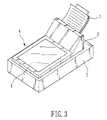
- FIG. 3 is the scheme of the body of transparency scanning module, cover and ADF (Automatic Document Feeder) of the invention.
- FIG. 4 is the 3-D scheme of the invention.
- FIG. 5 is the section view of the invention.
- FIG. 6 is the scheme of preferred embodiment of whole body for the invention.
- FIG. 7 is the scheme of another preferred embodiment of the invention.
- FIG. 3 is the combination scheme of transparency scanning module, cover and automatic document feeder. It shows that an automatic document feeder 2 is installed on a scanner 5 , and paper 1 is transferred and fixed on a position of the scanner 5 for scanning via automatic document feeder 2 , where is below the cover 4 . In this case, transparency 3 offers light source for transparent document.
- FIG. 3 clearly and easily shows the combination application of automatic document feeder and transparency scanning module. Automatic document feeder 2 , transparency scanning module 3 and cover 4 are embedded and cannot be taken apart.
- FIG. 4 which is a 3-D scheme. The difference between FIG. 3 and FIG. 4 is that this embodiment ignores automatic document feeder 2 and is applied on cover of scanning mechanism (as general scanners); the transparency scanning module 3 is installed in the cover 4 , and the features are:
- the transparency scanning module 3 is embedded in the cover 4 , and there are two fillisters 7 of a slot 8 .
- the slot 8 is for transparency scanning module 3 putting into.
- the two fillisters 7 are in an inner wall of slot 8 ; on the contrary positions of transparency scanning module 3 are another two connectors 6 for connecting two fillisters 7 .
- the two fillisters 7 on cover 4 and the two connectors 6 on transparency scanning module 3 can be connected and taken apart at any time.
- the central parts of the two fillisters 7 are made to be close together for embedding and holding two connectors 6 .
- a male pivot structure 9 is set at bottom of front end of cover 4 , and there is another female pivot structure 9 is set at the position of scanner relative to the position of the male pivot structure 9 , thus the open and close actions can be made for cover 4 .
- FIG. 5 is the section view of the present invention, which shows the relationship of transparency scanning module 3 and the design of light source layout.
- the transparency scanning module 3 is protruding at most central part in z direction, and the rim is thinner; on the contrary, cover 4 is formed as a hollow at central part, and the form is matched with transparency scanning module 3 .
- module 3 cannot be moved both at x and y directions.
- the combinations of afore said fillisters 7 with connectors 6 and the present transparency scanning module 3 with cover 4 make double fixing function.
- There is a light source line 10 designed at the connection of fillisters 7 and cover 4 then the line 10 goes to pivot structure 9 , wherein line 10 can be formed to reach the object of convenience of pivot structure 9 rotation.
- FIG. 6 is a preferred embodiment of the present invention.
- the embodiment is integrated to be described for prior art and the present invention.
- a transparency scanning module 3 is embedded with a cover 4 .
- a first reflect mirror 16 After light going through transparent document, then light goes to a first reflect mirror 16 , a second reflect mirror 17 , a third reflect mirror 18 and a lens 19 , finally emitting on a CCD 20 (Charge Couple Device).
- the afford said first reflect mirror 16 , second reflect mirror 17 , third reflect mirror 18 , lens 19 and CCD 20 are all in a light-path device 21 .
- the light-path device 21 is installed on a guide rod 22 and guided by the guide rod 22 .
- a motor 23 drives light-path device 21 via a belt 24 to make the device 21 moving back and forth.
- a lower light source 15 emitting light path is prior art, and it is for general document and not described any more hereinafter.
- the section of light source line 10 after pivot structure 9 connects to an adapter 11 in a scanner 5 , and then to a out line 12 and a plug 13 , therefore, the layout is offer the power of upper light source 14 .
- For the power layout of the lower light source 15 and motor 23 is prior art, and it is not described any more hereinafter.
- FIG. 7 is a preferred embodiment of cover of the present invention.
- transparency scanning module 3 is embedded into cover 4 from top of cover 4 ; the present embodiment is from bottom of cover 4 .
- the advantage is that there is no difference between transparency scanning module 3 and cover 4 in appearance.
- connectors 6 connect to fillisters 7 as same as afore said, and there are another three fasteners 25 connecting to another three fastening cavities 26 of cover 4 for strongly fixing and connecting.
- the present invention jumps out from the prior art, and gets rid of shortness of prior art to keep the necessary elements, thus not only the entity is lighter, but also that the cost is going down.
- the present is completely matching the present requirement of the scientific society.
Landscapes
- Engineering & Computer Science (AREA)
- Multimedia (AREA)
- Signal Processing (AREA)
- Facsimile Scanning Arrangements (AREA)
- Image Input (AREA)
Abstract
Description
Claims (15)
Priority Applications (1)
| Application Number | Priority Date | Filing Date | Title |
|---|---|---|---|
| US11/485,656 US7697173B2 (en) | 2001-08-03 | 2006-07-12 | Transparency scanning module |
Applications Claiming Priority (2)
| Application Number | Priority Date | Filing Date | Title |
|---|---|---|---|
| US09/921,729 US7092131B2 (en) | 2001-08-03 | 2001-08-03 | Transparency scanning module |
| US11/485,656 US7697173B2 (en) | 2001-08-03 | 2006-07-12 | Transparency scanning module |
Related Parent Applications (1)
| Application Number | Title | Priority Date | Filing Date |
|---|---|---|---|
| US09/921,729 Continuation US7092131B2 (en) | 2001-08-03 | 2001-08-03 | Transparency scanning module |
Publications (2)
| Publication Number | Publication Date |
|---|---|
| US20070035788A1 US20070035788A1 (en) | 2007-02-15 |
| US7697173B2 true US7697173B2 (en) | 2010-04-13 |
Family
ID=25445890
Family Applications (2)
| Application Number | Title | Priority Date | Filing Date |
|---|---|---|---|
| US09/921,729 Expired - Lifetime US7092131B2 (en) | 2001-08-03 | 2001-08-03 | Transparency scanning module |
| US11/485,656 Expired - Fee Related US7697173B2 (en) | 2001-08-03 | 2006-07-12 | Transparency scanning module |
Family Applications Before (1)
| Application Number | Title | Priority Date | Filing Date |
|---|---|---|---|
| US09/921,729 Expired - Lifetime US7092131B2 (en) | 2001-08-03 | 2001-08-03 | Transparency scanning module |
Country Status (1)
| Country | Link |
|---|---|
| US (2) | US7092131B2 (en) |
Cited By (1)
| Publication number | Priority date | Publication date | Assignee | Title |
|---|---|---|---|---|
| US11039026B2 (en) * | 2019-04-11 | 2021-06-15 | Avision Inc. | Multipurpose image capturing apparatus |
Families Citing this family (8)
| Publication number | Priority date | Publication date | Assignee | Title |
|---|---|---|---|---|
| US7092131B2 (en) * | 2001-08-03 | 2006-08-15 | Po-Hua Fang | Transparency scanning module |
| US7149012B2 (en) * | 2001-11-09 | 2006-12-12 | Po-Hua Fang | Image scanner |
| US8547603B2 (en) * | 2003-11-03 | 2013-10-01 | Hewlett-Packard Development Company, L.P. | Transparency imaging systems and methods |
| JP3817554B2 (en) * | 2004-01-16 | 2006-09-06 | キヤノン株式会社 | Image reading device |
| JP3919750B2 (en) * | 2004-01-21 | 2007-05-30 | キヤノン株式会社 | Image reading apparatus and image forming apparatus using the same |
| US20060285175A1 (en) * | 2005-06-17 | 2006-12-21 | Kuo-Kuang Wu | Scanner for penetrative documents |
| JP4858407B2 (en) * | 2006-11-27 | 2012-01-18 | ブラザー工業株式会社 | Image reading device |
| USD702245S1 (en) * | 2012-01-11 | 2014-04-08 | Victor Susman | Scanning frame |
Citations (18)
| Publication number | Priority date | Publication date | Assignee | Title |
|---|---|---|---|---|
| US4893196A (en) | 1987-04-09 | 1990-01-09 | Kabushiki Kaisha Toshiba | Image reading apparatus |
| US5289000A (en) * | 1992-07-22 | 1994-02-22 | Fuji Photo Film Co., Ltd. | Image reading method and apparatus determining synchronous position |
| US5467172A (en) | 1994-06-15 | 1995-11-14 | Liao; Chun-Chi | Image scanner transparency adaptor |
| US5781311A (en) * | 1994-08-24 | 1998-07-14 | Nikon Corporation | Planar light source and image reading device |
| US6002508A (en) * | 1998-11-13 | 1999-12-14 | Umax Data Systems Inc. | Optical scanner |
| US6163385A (en) | 1998-06-08 | 2000-12-19 | Kajander; Richard Emil | Integrated and auxiliary light for image scanners for scanning transparencies and method of lighting transparencies for image scanning |
| US6185011B1 (en) * | 1998-01-22 | 2001-02-06 | Acer Peripherals, Inc. | Flatbed scanner with top and bottom light sources and a moveable light shield |
| US6198088B1 (en) * | 1999-05-27 | 2001-03-06 | Xerox Corporation | Methods and apparatus for detecting a document on a platen |
| US6316766B1 (en) | 1998-10-08 | 2001-11-13 | Microtek International, Inc. | Scanner with light directing channel |
| US20020039205A1 (en) | 2000-10-02 | 2002-04-04 | Chun-Ying Chang | Transparent scanning apparatus |
| US20020075517A1 (en) * | 2000-12-18 | 2002-06-20 | Haining David S. | Photography scanner device |
| US6417937B1 (en) | 1999-03-30 | 2002-07-09 | Hewlett-Packard Company | Integrated automatic document feeder and active transparency adapter |
| US6614563B1 (en) * | 1999-03-30 | 2003-09-02 | Hewlett-Packard Development Company, L.P. | Flat panel illuminator active transparency adapter |
| US20050200917A1 (en) * | 2004-02-20 | 2005-09-15 | Seiko Epson Corporation | Image reading apparatus |
| US7092131B2 (en) * | 2001-08-03 | 2006-08-15 | Po-Hua Fang | Transparency scanning module |
| US20060268365A1 (en) * | 2005-05-27 | 2006-11-30 | Lexmark International, Inc. | Imaging apparatus configured for scanning a document |
| US20070058216A1 (en) * | 2005-09-15 | 2007-03-15 | Lite-On Technology Corporation | Scanner |
| US7388690B2 (en) * | 2005-05-27 | 2008-06-17 | Khageshwar Thakur | Method for calibrating an imaging apparatus configured for scanning a document |
Family Cites Families (1)
| Publication number | Priority date | Publication date | Assignee | Title |
|---|---|---|---|---|
| JP4450966B2 (en) * | 2000-10-03 | 2010-04-14 | 富士通株式会社 | Paper sheet identification device |
-
2001
- 2001-08-03 US US09/921,729 patent/US7092131B2/en not_active Expired - Lifetime
-
2006
- 2006-07-12 US US11/485,656 patent/US7697173B2/en not_active Expired - Fee Related
Patent Citations (19)
| Publication number | Priority date | Publication date | Assignee | Title |
|---|---|---|---|---|
| US4893196A (en) | 1987-04-09 | 1990-01-09 | Kabushiki Kaisha Toshiba | Image reading apparatus |
| US5289000A (en) * | 1992-07-22 | 1994-02-22 | Fuji Photo Film Co., Ltd. | Image reading method and apparatus determining synchronous position |
| US5467172A (en) | 1994-06-15 | 1995-11-14 | Liao; Chun-Chi | Image scanner transparency adaptor |
| US5781311A (en) * | 1994-08-24 | 1998-07-14 | Nikon Corporation | Planar light source and image reading device |
| US6185011B1 (en) * | 1998-01-22 | 2001-02-06 | Acer Peripherals, Inc. | Flatbed scanner with top and bottom light sources and a moveable light shield |
| US6163385A (en) | 1998-06-08 | 2000-12-19 | Kajander; Richard Emil | Integrated and auxiliary light for image scanners for scanning transparencies and method of lighting transparencies for image scanning |
| US6316766B1 (en) | 1998-10-08 | 2001-11-13 | Microtek International, Inc. | Scanner with light directing channel |
| US6002508A (en) * | 1998-11-13 | 1999-12-14 | Umax Data Systems Inc. | Optical scanner |
| US6417937B1 (en) | 1999-03-30 | 2002-07-09 | Hewlett-Packard Company | Integrated automatic document feeder and active transparency adapter |
| US6614563B1 (en) * | 1999-03-30 | 2003-09-02 | Hewlett-Packard Development Company, L.P. | Flat panel illuminator active transparency adapter |
| US6198088B1 (en) * | 1999-05-27 | 2001-03-06 | Xerox Corporation | Methods and apparatus for detecting a document on a platen |
| US20020039205A1 (en) | 2000-10-02 | 2002-04-04 | Chun-Ying Chang | Transparent scanning apparatus |
| US6850344B2 (en) * | 2000-10-02 | 2005-02-01 | Mustek Systems Inc. | Transparent scanning apparatus |
| US20020075517A1 (en) * | 2000-12-18 | 2002-06-20 | Haining David S. | Photography scanner device |
| US7092131B2 (en) * | 2001-08-03 | 2006-08-15 | Po-Hua Fang | Transparency scanning module |
| US20050200917A1 (en) * | 2004-02-20 | 2005-09-15 | Seiko Epson Corporation | Image reading apparatus |
| US20060268365A1 (en) * | 2005-05-27 | 2006-11-30 | Lexmark International, Inc. | Imaging apparatus configured for scanning a document |
| US7388690B2 (en) * | 2005-05-27 | 2008-06-17 | Khageshwar Thakur | Method for calibrating an imaging apparatus configured for scanning a document |
| US20070058216A1 (en) * | 2005-09-15 | 2007-03-15 | Lite-On Technology Corporation | Scanner |
Cited By (1)
| Publication number | Priority date | Publication date | Assignee | Title |
|---|---|---|---|---|
| US11039026B2 (en) * | 2019-04-11 | 2021-06-15 | Avision Inc. | Multipurpose image capturing apparatus |
Also Published As
| Publication number | Publication date |
|---|---|
| US7092131B2 (en) | 2006-08-15 |
| US20070035788A1 (en) | 2007-02-15 |
| US20030025952A1 (en) | 2003-02-06 |
Similar Documents
| Publication | Publication Date | Title |
|---|---|---|
| TW417397B (en) | Rod lens array, and image read apparatus and system using the same | |
| US7697173B2 (en) | Transparency scanning module | |
| US5945664A (en) | Image sensor with integrated illumination, image forming means, and image processing apparatus using the image sensor | |
| US7843611B2 (en) | High speed flatbed scanner comprising digital image-capture module with two-dimensional optical image photo-sensor or digital camera | |
| US5961337A (en) | Universal charging and data communication apparatus | |
| US7719613B2 (en) | Cradle for digital camera | |
| JP2000013568A (en) | Scanner device | |
| WO2001092781A1 (en) | Lightweight, energy-efficient, detachable computer light | |
| TW468329B (en) | Integrated optical imaging assembly | |
| US20030179390A1 (en) | Image reader attachable printer | |
| US20030206318A1 (en) | Retractable lamp for an improved document scanner paper path | |
| JP7470220B2 (en) | Image reading device and image forming device | |
| EP1026620B1 (en) | Expandable hand scanner with lens reduction optics | |
| EP1104623A1 (en) | Method and apparatus for keeping a document in focus during noncontact scanning | |
| TW563332B (en) | Space-saving flatbed scanner | |
| US7944590B2 (en) | Box for image reading apparatus, image reading apparatus and image forming apparatus | |
| US6522428B1 (en) | Structure of foldable optical path | |
| CN113918035A (en) | Computer mouse with enhanced functionality | |
| US6796500B1 (en) | Business card reader with a replaceable charging cradle | |
| US6710898B2 (en) | Modular scanner | |
| US7599104B2 (en) | Image reading apparatus and multi-functional apparatus having a plate-like pressing member | |
| JP3082825U (en) | Wireless transmission CMOS image sensor scanner | |
| US6075584A (en) | Multiple-resolution scanner | |
| US7990585B2 (en) | Circuit module integrating a light driver and an optical sensor | |
| JP2000089535A (en) | Image forming device |
Legal Events
| Date | Code | Title | Description |
|---|---|---|---|
| AS | Assignment |
Owner name: UMAX DATA SYSTEMS, INC.,TAIWAN Free format text: ASSIGNMENT OF ASSIGNORS INTEREST;ASSIGNOR:FANG, PO HUA;REEL/FRAME:018576/0411 Effective date: 20010711 Owner name: VEUTRON CORPORATION,TAIWAN Free format text: CHANGE OF NAME;ASSIGNOR:UMAX DATA SYSTEMS, INC.;REEL/FRAME:018576/0420 Effective date: 20021029 Owner name: TRANSPACIFIC IP, LTD.,TAIWAN Free format text: ASSIGNMENT OF ASSIGNORS INTEREST;ASSIGNOR:VEUTRON CORPORATION;REEL/FRAME:018576/0426 Effective date: 20050706 Owner name: VEUTRON CORPORATION, TAIWAN Free format text: CHANGE OF NAME;ASSIGNOR:UMAX DATA SYSTEMS, INC.;REEL/FRAME:018576/0420 Effective date: 20021029 Owner name: TRANSPACIFIC IP, LTD., TAIWAN Free format text: ASSIGNMENT OF ASSIGNORS INTEREST;ASSIGNOR:VEUTRON CORPORATION;REEL/FRAME:018576/0426 Effective date: 20050706 Owner name: UMAX DATA SYSTEMS, INC., TAIWAN Free format text: ASSIGNMENT OF ASSIGNORS INTEREST;ASSIGNOR:FANG, PO HUA;REEL/FRAME:018576/0411 Effective date: 20010711 |
|
| AS | Assignment |
Owner name: TRANSPACIFIC SYSTEMS, LLC, DELAWARE Free format text: ASSIGNMENT OF ASSIGNORS INTEREST;ASSIGNOR:TRANSPACIFIC IP LTD.;REEL/FRAME:023107/0267 Effective date: 20090618 Owner name: TRANSPACIFIC SYSTEMS, LLC,DELAWARE Free format text: ASSIGNMENT OF ASSIGNORS INTEREST;ASSIGNOR:TRANSPACIFIC IP LTD.;REEL/FRAME:023107/0267 Effective date: 20090618 |
|
| AS | Assignment |
Owner name: TITUSVILLE CANAVERAL LLC, DELAWARE Free format text: MERGER;ASSIGNOR:TRANSPACIFIC SYSTEMS, LLC;REEL/FRAME:030628/0681 Effective date: 20130213 |
|
| AS | Assignment |
Owner name: INTELLECTUAL VENTURES I LLC, DELAWARE Free format text: MERGER;ASSIGNOR:TITUSVILLE CANAVERAL LLC;REEL/FRAME:030639/0330 Effective date: 20130214 |
|
| REMI | Maintenance fee reminder mailed | ||
| LAPS | Lapse for failure to pay maintenance fees | ||
| STCH | Information on status: patent discontinuation |
Free format text: PATENT EXPIRED DUE TO NONPAYMENT OF MAINTENANCE FEES UNDER 37 CFR 1.362 |
|
| STCH | Information on status: patent discontinuation |
Free format text: PATENT EXPIRED DUE TO NONPAYMENT OF MAINTENANCE FEES UNDER 37 CFR 1.362 |
|
| FP | Lapsed due to failure to pay maintenance fee |
Effective date: 20140413 |