US7690118B2 - Bar steel cutting tool - Google Patents
Bar steel cutting tool Download PDFInfo
- Publication number
- US7690118B2 US7690118B2 US11/581,768 US58176806A US7690118B2 US 7690118 B2 US7690118 B2 US 7690118B2 US 58176806 A US58176806 A US 58176806A US 7690118 B2 US7690118 B2 US 7690118B2
- Authority
- US
- United States
- Prior art keywords
- blade body
- handle
- rotary blade
- shaft
- bar steel
- Prior art date
- Legal status (The legal status is an assumption and is not a legal conclusion. Google has not performed a legal analysis and makes no representation as to the accuracy of the status listed.)
- Expired - Fee Related, expires
Links
- 229910000831 Steel Inorganic materials 0.000 title claims abstract description 60
- 239000010959 steel Substances 0.000 title claims abstract description 60
- 238000005520 cutting process Methods 0.000 title claims abstract description 38
- 238000010008 shearing Methods 0.000 claims abstract description 4
- 238000009434 installation Methods 0.000 description 12
- 230000007423 decrease Effects 0.000 description 2
- 230000003872 anastomosis Effects 0.000 description 1
- 230000015572 biosynthetic process Effects 0.000 description 1
- 238000010276 construction Methods 0.000 description 1
- 230000002708 enhancing effect Effects 0.000 description 1
- 230000002349 favourable effect Effects 0.000 description 1
- 230000002401 inhibitory effect Effects 0.000 description 1
- 230000004048 modification Effects 0.000 description 1
- 238000012986 modification Methods 0.000 description 1
- 230000002035 prolonged effect Effects 0.000 description 1
- 230000006641 stabilisation Effects 0.000 description 1
- 238000011105 stabilization Methods 0.000 description 1
Images


Classifications
-
- B—PERFORMING OPERATIONS; TRANSPORTING
- B23—MACHINE TOOLS; METAL-WORKING NOT OTHERWISE PROVIDED FOR
- B23D—PLANING; SLOTTING; SHEARING; BROACHING; SAWING; FILING; SCRAPING; LIKE OPERATIONS FOR WORKING METAL BY REMOVING MATERIAL, NOT OTHERWISE PROVIDED FOR
- B23D29/00—Hand-held metal-shearing or metal-cutting devices
- B23D29/02—Hand-operated metal-shearing devices
- B23D29/023—Hand-operated metal-shearing devices for cutting wires
-
- B—PERFORMING OPERATIONS; TRANSPORTING
- B26—HAND CUTTING TOOLS; CUTTING; SEVERING
- B26D—CUTTING; DETAILS COMMON TO MACHINES FOR PERFORATING, PUNCHING, CUTTING-OUT, STAMPING-OUT OR SEVERING
- B26D5/00—Arrangements for operating and controlling machines or devices for cutting, cutting-out, stamping-out, punching, perforating, or severing by means other than cutting
- B26D5/08—Means for actuating the cutting member to effect the cut
- B26D5/18—Toggle-link means
-
- B—PERFORMING OPERATIONS; TRANSPORTING
- B26—HAND CUTTING TOOLS; CUTTING; SEVERING
- B26D—CUTTING; DETAILS COMMON TO MACHINES FOR PERFORATING, PUNCHING, CUTTING-OUT, STAMPING-OUT OR SEVERING
- B26D3/00—Cutting work characterised by the nature of the cut made; Apparatus therefor
- B26D3/16—Cutting rods or tubes transversely
Definitions
- the present invention relates to a bar steel cutting tool for cutting bar steel manually at a working site.
- a bar steel cutting tool As a tool for cutting bar steel to predetermined dimensions at working sites for civil engineering or construction, a bar steel cutting tool, as disclosed in Japanese Utility Model Application Publication No. 45-24715, has been known for many years.
- bar steel is inserted into concave blades of a fixed blade body and a rotary blade body at a position at which the concave blades of both bodies meet each other, and then, a handle is pressed down so as to rotate the rotary blade body and to cut out the bar steel.
- An inclined elongated hole is formed in the proximal portion of the handle, and a pin provided projectingly on the rotary blade body is slidably fitted therein. When the handle is pressed down, the pin is pressed by the elongated hole so that the rotary blade body is swung downwards so as to cut out the bar steel.
- an object of the present invention is to provide a bar steel cutting tool that has outstanding strength, durability, and stability, and that is capable of cutting bar steel with an excellent degree of cutting efficiency.
- the present invention provides a bar steel cutting tool in which are provided at the front end of a tool base a fixed blade body, and a rotary blade body that is capable of rotating around a first shaft by operating a handle in a condition in which it is fitted to the fixed blade body;
- the bar steel cutting tool shears bar steel with concave blades formed on the outer peripheries of the fixed blade body and the rotary blade body;
- the handle is constructed in such a way that the front end of its proximal portion is supported by a second shaft at a position above the tool base and the handle is equipped with an elongated hole extending in an oblique backward direction from the second shaft;
- the rotary blade body forms branch portions which nip both the right and left sides of the proximal portion of the handle at the rear end of an arm portion that extends backwards; and the branch portions are bent in an upward direction so as to bypass the second shaft and support both sides of the pin that slides within the interior of the elongated hole.
- the branch portions of the rotary blade body are constituted of two plates that are separated from the blade main body, if the concave blade in the rotary blade body becomes worn or damaged it becomes possible for only the blade main body of the rotary blade body to be replaced.
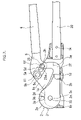
- FIG. 1 is a side view of major portions of the bar steel cutting tool of the present invention
- FIG. 2 is a sectional view taken along the line B-B of FIG. 2 ;
- FIG. 3 is a sectional view taken along the line A-A of FIG. 2 ;
- FIG. 4 is a sectional view taken along the line C-C of FIG. 3 ;
- FIG. 5 is a side sectional view of the bar steel cutting tool in an open state
- FIG. 6 is a side sectional view of the bar steel cutting tool at the time of cutting.
- FIG. 7 is a side sectional view of another embodiment.
- Reference numeral 1 denotes a tool base, a tool base 1 that has a pair of wall portions 1 a disposed opposite each other.
- the opposing wall portions 1 a are connected by connecting portions 1 b , 1 c , 1 d that are provided perpendicularly.
- the bottom portion of the wall portion 1 a is connected to a base portion 1 e that is provided perpendicularly to the wall portion 1 a .
- This base portion 1 e has mounting holes 1 f and mounting concave portions 1 g for mounting the bar steel cutting tool onto the floor for purposes of stabilization.
- a first shaft hole 1 h is formed at the front portion of the wall portion 1 a so that it goes through the opposing wall portion 1 a .
- a second shaft hole 1 i is formed in an upward position behind the first shaft hole 1 h at the top portion of the wall portion 1 a so that it goes through the opposing wall portion 1 a .
- a second shaft bearing portion in is provided projectingly on both of the inner sides of the second shaft hole 1 i in the opposing wall portion 1 a.
- a handle installation portion 1 j is formed in a depressed state so that a lower handle 20 can be installed, and the proximal portion of the lower handle 20 is fitted to the handle installation portion 1 j .
- the lower handle 20 is then installed onto the tool base 1 by inserting a bolt into a mounting hole 1 k so as to cross the handle installation portion 1 j .
- a member (not shown) is preferably provided at the rear end of the lower handle 20 for mounting the lower handle 20 onto the floor or the like.
- Reference numeral 2 denotes a fixed blade body that is fixed to the front end of the tool base 1 and is comprised of a circular blade portion 2 a and an installation portion 2 b that extends backward from this blade portion 2 a .
- the sectional shape of this fixed blade body 2 is substantially fig-like, with its top end lowered in such a way that the bottom end of the blade portion 2 a and the bottom portion of the installation portion 2 b are formed on a straight line.
- a shaft hole 2 c is formed on the center axis of the blade portion 2 b in such a way that it goes through the center axis.
- a concave blade 2 d which is dented in a U shape, is formed on the outer periphery of the top portion of the blade portion 2 a .
- the rear end of the installation portion 2 b of the fixed blade body 2 is nipped between a fixed protrusion 1 p and a connecting portion 1 d.
- the thickness of the installation portion 2 b is less than the thickness of the blade portion 2 a , and the side of the wall portion 1 a of the installation portion 2 b is on substantially the same plane as the side of the wall portion 1 a of the blade portion 2 a.
- the fixed blade body 2 is supported by the wall portion 1 a by means of a first shaft 10 which goes through the shaft hole 2 c and the first shaft hole 1 h in the tool base 1 .
- the top portion of the installation portion 2 b is pressed by a fixed protrusion 1 p that projects from the wall portion 1 a on one side, and the bottom portion of the installation portion 2 b is pressed by the connecting portion 1 d so as to inhibit the fixed blade body 2 from rotating, and to fix the fixed blade body 2 onto the tool base 1 .
- Reference numeral 3 denotes a rotary blade body, which is comprised of a circular blade portion 3 a and an arm portion 3 b that extends backward from this blade portion 3 a .
- the sectional shape of this rotary blade body 3 is substantially fig-like with its top end lowered in such a way that the bottom end of the blade portion 3 a and the bottom portion of the arm portion 3 b are formed on a straight line.
- a shaft hole 3 c is formed in the center of the blade portion 3 b .
- a concave blade 3 d which is dented in a U shape is formed on the outer periphery of the top portion of the blade portion 3 a .
- two nipping holes 3 e , 3 e are formed in parallel to one another.
- the rotary blade body 3 is disposed between the wall portion 1 a of the tool base 1 and the fixed blade body 2 in such a way that it overlaps the fixed blade body 2 .
- the rotary blade body 3 is supported rotatably by the wall portion 1 a , by the shaft hole 3 b in the rotary blade body 3 , by the shaft hole 2 d in the fixed blade body 2 , and by the first shaft 10 which goes through the first shaft hole 1 h of the tool base 1 so as to be rotatable in relation to the fixed blade body 2 .
- the thickness of the overlapping fixed blade body 2 and the rotary blade body 3 is substantially the same as an interval between the wall portions 1 a of the tool base 1 , although marginally less, the wall portions 1 a of the tool base 1 restrict movement in an axial direction of the fixed blade body 2 and the rotary blade body 3 and create only a minimum gap between the fixed blade body 2 and the rotary blade body 3 .
- the fixed blade body 2 and the rotary blade body 3 can rotate relative to each other while at the same time being attached to each other.
- the thickness of the arm portion 3 b of the rotary blade body 3 is set to be less than the thickness of the blade portion 3 a , a portion in which nipping holes 3 e are made in the arm portion 3 b is offset at the fixed blade body 2 and the center plane of the portion in which nipping holes 3 e are made in this arm portion 3 b is constructed so as to be on the same plane as a sliding face between the fixed blade body 2 and the rotary blade body 3 .
- Reference numeral 4 denotes two substantially L shaped plates, which are members for purposes of forming a branch portion at the rear end of the arm portion 3 b of the rotary blade body 3 .
- Nipping holes 4 a are formed at the front end and at an intersection point of the plate 4 , while a shaft hole 4 b is formed at the other front end.
- Reference numeral 23 denotes a nipping shaft and its outside diameter is set at a marginally lower level of length than the inside diameters of the nipping hole 3 e in the rotary blade body 3 and of the nipping hole 4 a in the plate 4 .
- Grooves, into which snap rings for a shaft are to be fitted, are formed along the entire periphery of both sides of the nipping shaft 23 .
- the plate 4 is disposed on both sides of the arm portion 3 b of the rotary blade body 3 in such a way that the shaft hole 4 b is located at an upward position the intersection point portion is located on the rear side and the nipping shaft 23 is inserted into both the nipping hole 3 e in the rotary blade body 3 and into the nipping hole 4 a in the plate 4 .
- the snap rings for the shaft are fitted to both sides of the nipping shaft 23 in such a way that the two plates 4 nip the arm portion 3 b of the rotary blade body 3 .
- These plates 4 are bent in an upward direction so as to avoid a second shaft 11 that will be described below.
- Reference numeral 5 denotes a proximal portion of the handle and reference numeral 6 denotes the handle.
- the front portion of the proximal portion 5 of the handle is plate-like and a handle installation portion 5 a having a substantially cylindrical section or a substantially cylindrical column section is extended a rear portion thereof in a backward direction of the tool.
- the handle 6 is installed on this handle installation portion 5 a .
- a second shaft hole 5 b is formed at the front end of the proximal portion 5 of the handle.
- a shaft portion 5 c is projected in an axial direction at of both sides of the second shaft hole 5 b .
- the width of this shaft portion 5 c is set at a marginally lower level than the width of the inner side of the second shaft bearing in of the tool base 1 .
- the proximal portion 5 of the handle is disposed inside the wall portions 1 a of the tool base 1 , and the second shaft 11 is inserted into the second shaft hole 1 i in the wall portion 1 a and into the second shaft hole 5 b in the proximal portion 5 of the handle so that the proximal portion 5 of the handle is supported by the tool base 1 by means of the second shaft 11 .
- An elongated hole 5 d is provided from a first point 5 e located downwards at the back of the second shaft hole 5 b in the proximal portion 5 of the handle to a second point 5 f located downwards at the back of this first point 5 e .
- the second shaft hole 5 b and the first point 5 e and the second point 5 f of the elongated hole 5 d are constructed so to be on the same straight line.
- Reference numeral 25 denotes a pin, and a collar 25 a is fitted onto the outer periphery of this pin 25 so that the pin slides and rotates into the elongated hole 5 d . Grooves into which snap rings are to be fitted are formed along the entire periphery of both sides of the pin 25 .
- the elongated hole 5 d portion of the proximal portion 5 of the handle is nipped by the two plates 4 and the pin 25 is inserted into the elongated hole 5 d and the shaft holes 4 b in the plates 4 .
- the snap rings for the shaft are fitted on to both sides of the pin 25 so as to prevent the pin 25 from falling down.
- the central plane of the arm portion 3 b of the rotary blade body 3 is so as constructed so as to be on the same plane as the central plane of a portion nipped by the plates 4 of the proximal portion 5 of the handle.
- the plate 4 of the rotary blade body 3 makes contact with the shaft portion 5 c of the proximal portion 5 of the handle so as to inhibit the rotary blade body 3 from rotating.
- a portion of the shaft portion 5 c makes contact with the arm portion 2 b is of a shape of anastomosis with the plate 4 , without making a point contact therewith.
- the plate 4 formed at the back of the rotary blade body 3 is bent in an upward direction so as to bypass the second shaft 11 , the rotary blade body 3 never interferes with the shaft portion 5 c of the proximal portion 5 of the handle even in an open state, as shown in FIG. 5 .
- the rear side of the concave blade 2 d of the fixed blade body 2 is inclined in such a way that it narrows from its front side in an inward direction.
- the front side of the concave blade 3 d of the rotary blade body 3 is inclined in such a way that it expands from its front side in an inward direction.
- the concave blades 2 d , 3 d are opened by raising the handle 6 (state shown in FIG. 5 ) and bar steel is inserted into the concave blades 2 d , 3 d .
- the pin 25 is located near an intermediate point between the first point 5 e and the second point 5 f of the elongated hole 25 .
- the bar steel cutting tool is preferably constructed in such a way that the first shaft 10 , the second shaft 11 and the shaft hole 4 b in the plate 4 are located on an identical straight line, and that the axis of the pin 25 is located at the first point 5 e of the elongated hole 5 d.
- the load pressing down on the pin 25 is a/b relative to the load pressing down on the handle 6 .
- the bar steel cutting tool is constructed in such a way that the first shaft 10 , the second shaft 11 and the shaft hole 4 b in the plate 4 are on the same straight line whenever the concave blades 2 d , 3 d bite the bar steel, the direction of a force applied to the pin 25 , and the trajectory of the shaft hole 4 b in the plate 4 rotating around the first shaft 10 , are made to be equal by the elongated hole 5 d in the proximal portion 5 of the handle, and by means of the elongated hole 5 d in the proximal portion 5 of the handle a load acting on the pin 25 accordingly comes to be applied to the rotary blade body 3 without escaping.
- a force acting on the bar steel by means of the concave blades 2 d , 3 d is ac/bd relative to the force pressing down on the handle 6 , and it thus becomes possible for bar steel to be cut out with a modest degree of operational force. If the shaft center of the pin 25 is located at the first point 5 e within the elongated hole 5 d , the distance b becomes the shortest possible and at the times of cutting a maximum load can thus be applied to the bar steel.
- the pin 25 slides from the first point 5 e in the direction of the second point 5 f , and the distance b is thereby prolonged, thus making it possible for the rotary blade body 3 to be rotated with a smaller rotation angle of the handle 6 , and thereby enhancing working efficiency.
- the load acting on the bar steel decreases because distance b increases, the area of a face of the bar steel that is cut decreases as the bar steel is sheared, and because the bar steel can be sheared with a smaller load, it becomes possible for the bar steel to be cut smoothly without the need to increase an operational force for pressing down on the handle 6 .
- the diameter of a bar of steel to be cut by the bar steel cutting tool of the present invention can, for example, be ⁇ 13 mm- ⁇ 16 mm.
- the bar steel cutting tool is preferably constructed in such a way that whenever the concave blades 2 d , 3 d bite the bar steel the first shaft 10 , the second shaft 11 and the shaft center of the pin 25 inserted into the shaft hole 4 b in the plate 4 are on an identical straight line that is appropriate for the diameter of the bar steel to be cut.
- the bottom portion of the arm portion 3 b of the second blade portion 3 makes contact with the connecting portion 1 d of the tool base 1 , as shown in FIG. 3 , thereby inhibiting a rotation of the handle 6 .
- the concave blades 2 d , 3 d adopt a closed state in which they do not communicate with each other, and consequently, the bar steel can be completely cut by shearing.
- the central plane of the arm portion 3 b of the rotary blade body 3 and the central plane of the portion nipped by the plates 4 of the proximal portion 5 of the handle are constructed on the same plane, and the sliding face between the fixed blade body 2 and the rotary blade body 3 and the central plane of the portion nipped by the plates 4 of the proximal portion 5 of the handle are constructed on the same plane, no load escapes, the requisite operational force is reduced and the bar steel can be cut out efficiently.
- FIG. 7 shows another embodiment of the present invention.
- a branch portion which nips the proximal portion 5 of the handle from both the right and left sides is formed integrally with the rotary blade body 3 .
- the branch portion is bent upwards so as to bypass the second shaft 11 , and both sides of the pin 25 which slides within the elongated hole 5 d are supported.
Landscapes
- Engineering & Computer Science (AREA)
- Mechanical Engineering (AREA)
- Life Sciences & Earth Sciences (AREA)
- Forests & Forestry (AREA)
- Shearing Machines (AREA)
Abstract
Description
Claims (4)
Applications Claiming Priority (2)
| Application Number | Priority Date | Filing Date | Title |
|---|---|---|---|
| JP2006-205970 | 2006-07-28 | ||
| JP2006205970A JP2008030150A (en) | 2006-07-28 | 2006-07-28 | Cutting tool for steel bar |
Publications (2)
| Publication Number | Publication Date |
|---|---|
| US20080022531A1 US20080022531A1 (en) | 2008-01-31 |
| US7690118B2 true US7690118B2 (en) | 2010-04-06 |
Family
ID=38984660
Family Applications (1)
| Application Number | Title | Priority Date | Filing Date |
|---|---|---|---|
| US11/581,768 Expired - Fee Related US7690118B2 (en) | 2006-07-28 | 2006-10-16 | Bar steel cutting tool |
Country Status (2)
| Country | Link |
|---|---|
| US (1) | US7690118B2 (en) |
| JP (1) | JP2008030150A (en) |
Cited By (5)
| Publication number | Priority date | Publication date | Assignee | Title |
|---|---|---|---|---|
| US20100236080A1 (en) * | 2009-03-20 | 2010-09-23 | Hsin-Te Huang | Wire Cutting Device |
| US8307557B1 (en) * | 2008-12-17 | 2012-11-13 | Rodgers Timothy J | Foot operated cutter |
| US9446527B1 (en) * | 2015-08-06 | 2016-09-20 | Paul Brainard | Pull-type cutters |
| US9656399B2 (en) | 2015-08-06 | 2017-05-23 | Paul Brainard | Pull-type cutters |
| US20240197379A1 (en) * | 2022-12-14 | 2024-06-20 | Sg, Llc | In situ rod cutters |
Families Citing this family (5)
| Publication number | Priority date | Publication date | Assignee | Title |
|---|---|---|---|---|
| CN103950054A (en) * | 2014-04-28 | 2014-07-30 | 于法周 | Bar material cutter |
| CN105834509B (en) * | 2016-05-18 | 2018-06-05 | 威海市威力高档工具有限公司 | Labor-saving bolt cutter |
| CN106513829B (en) * | 2016-08-31 | 2019-05-28 | 浙江连翔五金科技股份有限公司 | Clamp thread |
| DE102019108632A1 (en) * | 2019-04-02 | 2020-10-08 | Wolfcraft Gmbh | Levered cutting device |
| CN117773218B (en) * | 2023-12-29 | 2025-11-11 | 福建亿松机械有限公司 | Hydraulic shear with adjustable shear tightness and assembly method |
Citations (6)
| Publication number | Priority date | Publication date | Assignee | Title |
|---|---|---|---|---|
| US2385835A (en) * | 1944-01-31 | 1945-10-02 | Elmer Brandell | Lever construction |
| US2647312A (en) * | 1949-05-12 | 1953-08-04 | Elmer Brandell | Hand tool |
| US4058893A (en) * | 1976-06-25 | 1977-11-22 | Boyajian Alfred | Bolt cutter |
| US5187869A (en) * | 1990-04-27 | 1993-02-23 | Heiss Juergen K | Nipper instrument for cutting surgical nails, wires or the like |
| US20020170182A1 (en) * | 2001-05-16 | 2002-11-21 | Nordlin William F. | Cable cutter/crimper mechanism |
| US20040134073A1 (en) * | 2003-01-14 | 2004-07-15 | Minoru Kochi | Manual cable cutter |
Family Cites Families (2)
| Publication number | Priority date | Publication date | Assignee | Title |
|---|---|---|---|---|
| JPS4524715Y1 (en) * | 1967-04-03 | 1970-09-28 | ||
| JPS60190519A (en) * | 1984-03-12 | 1985-09-28 | Sumitomo Metal Ind Ltd | Method for directly softening and rolling two-phase stainless steel bar |
-
2006
- 2006-07-28 JP JP2006205970A patent/JP2008030150A/en active Pending
- 2006-10-16 US US11/581,768 patent/US7690118B2/en not_active Expired - Fee Related
Patent Citations (6)
| Publication number | Priority date | Publication date | Assignee | Title |
|---|---|---|---|---|
| US2385835A (en) * | 1944-01-31 | 1945-10-02 | Elmer Brandell | Lever construction |
| US2647312A (en) * | 1949-05-12 | 1953-08-04 | Elmer Brandell | Hand tool |
| US4058893A (en) * | 1976-06-25 | 1977-11-22 | Boyajian Alfred | Bolt cutter |
| US5187869A (en) * | 1990-04-27 | 1993-02-23 | Heiss Juergen K | Nipper instrument for cutting surgical nails, wires or the like |
| US20020170182A1 (en) * | 2001-05-16 | 2002-11-21 | Nordlin William F. | Cable cutter/crimper mechanism |
| US20040134073A1 (en) * | 2003-01-14 | 2004-07-15 | Minoru Kochi | Manual cable cutter |
Cited By (7)
| Publication number | Priority date | Publication date | Assignee | Title |
|---|---|---|---|---|
| US8307557B1 (en) * | 2008-12-17 | 2012-11-13 | Rodgers Timothy J | Foot operated cutter |
| US20100236080A1 (en) * | 2009-03-20 | 2010-09-23 | Hsin-Te Huang | Wire Cutting Device |
| US9446527B1 (en) * | 2015-08-06 | 2016-09-20 | Paul Brainard | Pull-type cutters |
| US9656399B2 (en) | 2015-08-06 | 2017-05-23 | Paul Brainard | Pull-type cutters |
| US20170217006A1 (en) * | 2015-08-06 | 2017-08-03 | Paul Brainard | Pull-type cutters |
| US10730195B2 (en) | 2015-08-06 | 2020-08-04 | Paul Brainard | Pull-type cutters |
| US20240197379A1 (en) * | 2022-12-14 | 2024-06-20 | Sg, Llc | In situ rod cutters |
Also Published As
| Publication number | Publication date |
|---|---|
| US20080022531A1 (en) | 2008-01-31 |
| JP2008030150A (en) | 2008-02-14 |
Similar Documents
| Publication | Publication Date | Title |
|---|---|---|
| US7690118B2 (en) | Bar steel cutting tool | |
| JP5517249B2 (en) | Demolition cutting machine | |
| US6926217B1 (en) | Heavy-duty demolition apparatus with replaceable tip and rotatable cross blade | |
| CN109551043A (en) | The puncture tip plug-in unit and end head accessory cut are cut and are removed in dismounting | |
| AU2003220337B2 (en) | Crimping tool head with reinforcing beams for optimizing weight | |
| US6418773B1 (en) | Rebar bender/cutter | |
| JP4906553B2 (en) | Long body support | |
| US20150340849A1 (en) | Manual cable cutter | |
| EP3829835B1 (en) | Hand operated shearing tool | |
| MX2007015045A (en) | Manual wrench for actuating cylindrical elements. | |
| JP2013198336A (en) | Cutter for remote control | |
| JP4638240B2 (en) | Crank shear with two blade pairs for cutting a rolled strip | |
| KR200310332Y1 (en) | Meat saw machine having a safety pushing bar | |
| JP3779930B2 (en) | Cutting tool for support member | |
| EP2221146B1 (en) | Punch nipper, in particular for metal section bars | |
| KR200191088Y1 (en) | Steel cutter | |
| EP2672018A1 (en) | Blade positioning structure for a shear for a works machine | |
| US330175A (en) | Degeipt | |
| GB2449644A (en) | Combined pivoted cutting tool and shovel | |
| US632267A (en) | Shears. | |
| JP6697065B2 (en) | How to install the baseboard device for temporary scaffolding | |
| JP4399225B2 (en) | Pipe breaker | |
| KR100859285B1 (en) | Combined Structure of Excavator Bucket and Work Plate | |
| JP6576900B2 (en) | Cutting tool | |
| JP3113712U (en) | Steel frame repair tool |
Legal Events
| Date | Code | Title | Description |
|---|---|---|---|
| AS | Assignment |
Owner name: MCC CORPORATION, JAPAN Free format text: ASSIGNMENT OF ASSIGNORS INTEREST;ASSIGNOR:YAMAKADO, AKIHIRO;REEL/FRAME:018601/0962 Effective date: 20061114 Owner name: MCC CORPORATION,JAPAN Free format text: ASSIGNMENT OF ASSIGNORS INTEREST;ASSIGNOR:YAMAKADO, AKIHIRO;REEL/FRAME:018601/0962 Effective date: 20061114 |
|
| STCF | Information on status: patent grant |
Free format text: PATENTED CASE |
|
| FPAY | Fee payment |
Year of fee payment: 4 |
|
| FPAY | Fee payment |
Year of fee payment: 8 |
|
| FEPP | Fee payment procedure |
Free format text: MAINTENANCE FEE REMINDER MAILED (ORIGINAL EVENT CODE: REM.); ENTITY STATUS OF PATENT OWNER: SMALL ENTITY |
|
| LAPS | Lapse for failure to pay maintenance fees |
Free format text: PATENT EXPIRED FOR FAILURE TO PAY MAINTENANCE FEES (ORIGINAL EVENT CODE: EXP.); ENTITY STATUS OF PATENT OWNER: SMALL ENTITY |
|
| STCH | Information on status: patent discontinuation |
Free format text: PATENT EXPIRED DUE TO NONPAYMENT OF MAINTENANCE FEES UNDER 37 CFR 1.362 |
|
| FP | Lapsed due to failure to pay maintenance fee |
Effective date: 20220406 |