US7685755B1 - Recoil system - Google Patents
Recoil system Download PDFInfo
- Publication number
- US7685755B1 US7685755B1 US12/008,558 US855808A US7685755B1 US 7685755 B1 US7685755 B1 US 7685755B1 US 855808 A US855808 A US 855808A US 7685755 B1 US7685755 B1 US 7685755B1
- Authority
- US
- United States
- Prior art keywords
- forend
- handgrip
- recoil reduction
- recoil
- reduction system
- Prior art date
- Legal status (The legal status is an assumption and is not a legal conclusion. Google has not performed a legal analysis and makes no representation as to the accuracy of the status listed.)
- Expired - Fee Related
Links
Images


Classifications
-
- F—MECHANICAL ENGINEERING; LIGHTING; HEATING; WEAPONS; BLASTING
- F41—WEAPONS
- F41A—FUNCTIONAL FEATURES OR DETAILS COMMON TO BOTH SMALLARMS AND ORDNANCE, e.g. CANNONS; MOUNTINGS FOR SMALLARMS OR ORDNANCE
- F41A25/00—Gun mountings permitting recoil or return to battery, e.g. gun cradles; Barrel buffers or brakes
- F41A25/10—Spring-operated systems
-
- F—MECHANICAL ENGINEERING; LIGHTING; HEATING; WEAPONS; BLASTING
- F41—WEAPONS
- F41C—SMALLARMS, e.g. PISTOLS, RIFLES; ACCESSORIES THEREFOR
- F41C23/00—Butts; Butt plates; Stocks
- F41C23/06—Stocks or firearm frames specially adapted for recoil reduction
-
- F—MECHANICAL ENGINEERING; LIGHTING; HEATING; WEAPONS; BLASTING
- F41—WEAPONS
- F41C—SMALLARMS, e.g. PISTOLS, RIFLES; ACCESSORIES THEREFOR
- F41C23/00—Butts; Butt plates; Stocks
- F41C23/16—Forestocks; Handgrips; Hand guards
-
- F—MECHANICAL ENGINEERING; LIGHTING; HEATING; WEAPONS; BLASTING
- F41—WEAPONS
- F41G—WEAPON SIGHTS; AIMING
- F41G11/00—Details of sighting or aiming apparatus; Accessories
- F41G11/001—Means for mounting tubular or beam shaped sighting or aiming devices on firearms
- F41G11/003—Mountings with a dove tail element, e.g. "Picatinny rail systems"
Definitions
- the present invention is directed generally to a recoil reduction system. More specifically, the present invention is directed to a recoil reduction system that is attached are coupled to or embedded within the forearm of a firearm or other device.
- recoil that affects the person firing the weapon.
- firearms such as shotguns and rifles
- the rear end of the butt stock is positioned against the shooter's shoulder and recoil often causes the shooter to raise the front of the firearm each time the weapon is fired.
- recoil varies depending upon the amount of explosive being fired and the recoil can result in pain and/or bruising to the shoulder area of the person firing the weapon.
- the recoil being detrimental to a shooter's accuracy is where the firearm is a shotgun being used for skeet shooting by a male or a female.
- recoil systems for the butt stock of a firearm have been very expensive and the inexpensive systems did not function properly.
- Two examples of expensive systems are a hydro-coil fluid dampening system and a pneumatic air chamber system.
- the present inexpensive recoil systems utilize compression coil springs to absorb the recoil forces. If the compression coil spring is a little too strong, you get more recoil than with a regular firearm. If the compression coil spring is not strong enough it is worse, in that it gives the gun some travel and it is the same as holding the butt stock too loosely.
- the novel recoil reduction system has been designed to be used with firearms such as shotguns and rifles.
- the recoil reduction structure is mounted forwardly of the receiver of the firearm.
- the recoil reduction structure is incorporated on the bottom wall of a forend and having an uptight handgrip secured to the bottom of the forend.
- the recoil reduction structure incorporates an inverted T-shaped rail extending downwardly from the forend that travels reciprocally forward and back in a track formed in the top end of the handgrip member.
- the handgrip member is gripped by the shooter's forward hand and when the gun is fired, the recoil action takes place forwardly of the receiver.
- the shooter can hold the firearm with the butt of the firearm spaced from the shooter's shoulder with out receiving a kick that stuns or bruises the shooter's shoulder.
- the novel recoil reduction system can also be incorporated into the structure of a forend that does not have a handgrip member.
- the novel recoil reduction system can also be installed into the long gun stock of a rifle at a location forward of the receiver. Again in this instance, the shooter's front hand would be gripping the cover member located beneath a cutout cavity in the bottom surface of the long gun stock.
- this invention provides a novel recoil system for a firearm that minimizes the amount of recoil force experienced by the person firing the weapon.
- This invention separately provides a novel recoil system for a firearm that minimizes pain to the shoulder of the person firing the weapon due to recoil forces.
- This invention separately provides a novel recoil system for a firearm that requires limited modification to the forend of a shotgun.
- This invention separately provides a novel recoil system for a firearm that utilizes a block of elastomer material.
- This invention separately provides a novel recoil system for the butt stock of a firearm that is easily mounted on the magazine tube of a shotgun.
- This invention separately provides a novel recoil system for shotguns and rifles that is economical to manufacture and market.
- This invention separately provides a novel double recoil system for a handgrip attached to a forend.
- This invention separately provides a novel recoil reduction system that can be installed into a long gun stock such as used with dries.
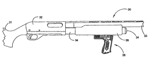
- FIG. 1 is a side elevation view of a shotgun illustrating the recoil reduction system mounted in a handgrip member secured to the bottom of the forend;
- FIG. 2 is an enlarged side elevation view of a forend having the recoil reduction system mounted in the handgrip member;
- FIG. 3 is a top plan view of the forend illustrated in FIG. 2 ;
- FIG. 4 is a rear elevation view of FIG. 2 ;
- FIG. 5 is a front elevation view of FIG. 2 ;
- FIG. 6 is a vertical cross section view illustrating a first embodiment of the recoil reduction system mounted in the handgrip member
- FIG. 7 is a vertical cross section view illustrating a second embodiment of the recoil reduction system mounted in the handgrip member
- FIG. 8 is a vertical cross section view illustrating a third embodiment of the recoil reduction system mounted in the handgrip member
- FIG. 9 is a vertical cross section view illustrating a fourth embodiment of the recoil reduction system mounted in the handgrip member
- FIG. 10 is a side elevation view of a shotgun illustrating the recoil reduction system mounted within the interior of the forend member;
- FIG. 11 is a top plan view of the forend member illustrated in FIG. 10 ;
- FIG. 12 is a right side elevation view of the forend member illustrated in FIG. 10 ;
- FIG. 13 is a cross sectional view taken along lines 13 - 13 of FIG. 12 ;
- FIG. 14 is a side elevation view of the support unit for the recoil reduction structure received in the forend illustrated in FIGS. 11-13 ;
- FIG. 15 is a front elevation view of the support unit illustrated in FIG. 14 ;
- FIG. 16 is a rear elevation view of the support unit illustrated in FIG. 14 ;
- FIG. 17 is a bottom plan view of the support unit illustrated in FIG. 14 ;
- FIG. 18 is an enlarged view of FIG. 2 with portions of the handgrip member illustrated in cross section;
- FIG. 19 is a front elevation view of FIG. 18 with portions shown in cross section;
- FIG. 20 is a side elevation view of a rifle having the recoil reduction system positioned forwardly of the receiver in the bottom of the long gun stock;
- FIG. 21 is a partial bottom plan view of FIG. 20 ;
- FIG. 22 is a top plan view of the cover member
- FIG. 23 is a side elevation of the cover member
- FIG. 24 is a front elevation view of the cover member
- FIG. 25 is a side elevation view of an alternative embodiment of the cover member having a retractable handgrip member secured to its bottom surface;
- FIG. 26 is a side elevation view of the alternative cover member showing the handgrip member in its retracted position
- FIG. 27 is a side elevation view illustrating a flashlight and a laser light mounted on the front end of a handgrip member.
- FIGS. 28-37 show various exemplary embodiments and exemplary elements of an improved recoil reduction system according to this invention.
- FIGS. 1-9 and 18 - 19 The novel recoil reduction system for a firearm will now be described by referring to FIGS. 1-9 and 18 - 19 .
- a shotgun 30 is illustrated in FIG. 1 having butt stock 31 , a receiver 32 , a gun barrel 33 , a magazine 34 , a forend 35 and a handgrip member 36 .
- the recoil reduction system is mounted within handgrip member 36 .
- FIGS. 2-5 and 18 - 19 illustrate views of the forend 35 from various sides and angles.
- FIG. 4 is a rear elevation view and it shows that forend 35 has a generally U-shaped transverse profile with a ring 38 formed at its front end. Ring 38 has a bore hole 39 that would telescope over magazine 34 .
- the remainder of forend 35 has a left side wall 40 , a right side wall 41 , and a bottom wall 42 .
- a plurality of screws 44 secure an inverted T-shaped rail 46 to the bottom surface of forend 35 .
- Handgrip member 36 has a longitudinally extending inverted T-shaped track 48 along which rail 46 reciprocally travels.
- Track 48 has a chamber 49 formed in its rear end that receives an elastomer block 51 having a cylindrical shape.
- Track 48 and chamber 49 are formed in track housing 52 that extends rearwardly from the top end of handgrip 36 .
- a cavity 53 is formed in the bottom surface of rail 46 .
- a primary chamber 54 extends upwardly through almost all of the height of handgrip member 36 .
- a lever 56 is pivotally mounted in primary chamber 54 by a pivot pin 57 .
- a cam roller 58 is mounted on the top end of lever 56 by a pin 59 .
- a retainer ring 61 is mounted on the bottom end of lever 56 by a pin 62 .
- a coil spring 63 has its top hook member 64 captured in retainer 61 .
- Coil spring 63 has a bottom hook member 65 captured by the rigid pin 66 .
- Forend 35 is rigidly secured to the magazine 34 or other structure that is rigidly secured to receiver 32 .
- a forend 35 recoils rearwardly causing rail 46 to also travel in the same direction.
- the elastomer block 51 is compressed to reduce some of the recoil.
- Cam roller 58 is pivoted rearwardly about pivot pin 57 causing coil spring 63 to be stretched and then returned to its static position and this also provides recoil reduction.
- FIG. 7 The first variation of the recoil reducing structure in the handgrip member 36 is illustrated in FIG. 7 .
- a rod 68 has its bottom end connected to plate 69 and its top end is pivoted on pin 62 .
- An elastomer tube 70 is telescoped over rod 68 and its top end bears against pins 70 and 71 . Rearward travel of rail 46 will pivot lever 56 rearwardly causing elastomer tube 70 to be compressed and reduce recoil.
- FIG. 8 A second alternative recoil reducing structure is illustrated in FIG. 8 . It has a leaf spring 73 having a stressed curvature in its static state. Its top end is captured by attachment structure 74 on the bottom end of lever 56 and its bottom end is captured in slot 75 in the inner wall of handgrip member 36 . Rearward travel of rail 46 will compress elastomer block 51 causing recoil reduction. Likewise spring 73 will be stretched upwardly when lever 56 is rotated rearwardly. This also reduces the recoil force.
- FIG. 9 A third alternative recoil structure is illustrated in FIG. 9 . It has a coil spring 77 in rail chamber 49 .
- a screw 79 has its top end captured by pin 62 .
- a coil spring 80 surrounds screw 79 and has a nut 81 on its bottom end. Pins 70 and 71 press against the top end of spring 80 .
- coil spring 77 reduces the recoil force.
- spring 80 would be compressed to also reduce recoil force.
- the recoil reduction system is mounted inside forend 85 .
- Forend 85 has a handrest stop 86 extending downwardly from its forward end to prevent the shooter's hand from slipping off the forend.
- FIGS. 11-13 illustrate different views of forend 85 .
- Forend 85 is generally U-shaped throughout most of its length. It has a left side wall 86 , a right side wall 87 , a top wall 88 , and a bottom wall 89 .
- a portion of forend 85 has a connecting wall member 91 at its top end and a bore hole 92 is formed for telescopically receiving the magazine 34 .
- Finger grooves 92 are formed along the outside surface of the respective left and fight side walls.
- Forend 85 has an interior cavity 94 having outwardly extending tracks 95 adjacent its bottom end.
- Support unit 97 is a solid piece of material that is telescopically received in cavity 94 of forend 85 .
- Support unit 97 has a top wall 98 , a left side wall 99 , a right side wall 100 , a bottom wall 101 and rails 103 extend outwardly from the respective side walls adjacent bottom wall 101 .
- a bore hole 104 extends the length of support unit 97 so that it telescopes over magazine 34 .
- Grooves 105 extend inwardly into rails 103 and these grooves receive set screws 106 extending inwardly from the side walls of forend 85 .
- Bottom wall 101 is best seen in FIG. 7 .
- the recoil reduction system is mounted in a rifle 123 .
- Rifle 123 has a recoil suppression butt stock assembly 125 , a receiver 126 , a gun barrel 127 , and a long gun stock 128 .
- long gun stock 128 would have a removable front piece 130 .
- stock cover 134 can only be installed by removing front piece 130 .
- Long gun stock 128 has three identifiable portions, butt stock portion 136 , middle portion 137 , and front portion 138 .
- Front portion 138 is located forward of receiver 128 .
- Primary recess 132 has a bottom wall 140 .
- Bottom wall 140 has rails 142 extending along its lateral edges and above it are formed an inwardly extending track 144 .
- a recess 146 is formed in bottom wall 140 and lever 147 is mounted on a pivot pin 148 therein.
- a cam roller 149 is pivotally secured to one end of lever 147 .
- a retainer member 150 is secured to the other end of 147 and it captures one end of spring 152 .
- the other end of spring 152 is captured by a pin 153 .
- the top portion of spring 152 extends into a deeper recess 155 .
- a cover member 160 has a front end 161 , a rear end 162 , a left side wall 163 , and a fight side wall 164 . Finger grips 167 are formed in both of the side walls 163 and 164 .
- Cover member 160 has a bottom wall 170 having a bore hole 172 therein. Tracks 174 are formed on the inner side wall surfaces and they telescopically receive rails 142 .
- a screw 176 extends upwardly through bore hole 172 and is threaded into the bottom end era tapered nut 178 . Once cover 160 is slid onto rails 142 , screw 176 is tightened which causes tapered nut 178 to push upwardly until it contacts cam roller 149 and preloads spring 152 .
- the length of cover member 160 is about 1 inch short of the length of primary recess 132 .
- long gun stock 128 will travel rearwardly while cover member 160 is held stationary by the forward hand of the person holding the rifle.
- Cam roller 149 will contact tapered nut 178 causing lever 147 to pivot forwardly causing spring 152 to be stretched thereby reducing the recoil force.
- cover member 160 is illustrated as having a handgrip member 190 with its top end pivotally secured to hinge assembly 192 .
- Handgrip member 190 rotates around pivot pin 194 to its retracted position.
- bore holes 194 and 195 align to receive a locking pin 197 .
- FIG. 27 is a side elevation view illustrating a flashlight and a laser light mounted on the front end of a handgrip member.
- FIGS. 28-37 show various exemplary embodiments and exemplary elements of an improved recoil reduction system according to this invention.
Landscapes
- Engineering & Computer Science (AREA)
- General Engineering & Computer Science (AREA)
- Aiming, Guidance, Guns With A Light Source, Armor, Camouflage, And Targets (AREA)
Abstract
Description
Claims (15)
Priority Applications (5)
| Application Number | Priority Date | Filing Date | Title |
|---|---|---|---|
| US12/008,558 US7685755B1 (en) | 2005-05-19 | 2008-01-11 | Recoil system |
| US12/263,656 US7954268B2 (en) | 2005-05-19 | 2008-11-03 | Torsion spring recoil system for the forend of a firearm |
| US12/263,674 US20100275484A1 (en) | 2005-05-19 | 2008-11-03 | Rail mounted recoil system for the forend of a firearm |
| US12/657,652 US8205371B1 (en) | 2005-05-19 | 2010-01-25 | Recoil reducing systems for a stock |
| US13/482,041 US8296986B1 (en) | 2005-05-19 | 2012-05-29 | Stock for a firearm |
Applications Claiming Priority (2)
| Application Number | Priority Date | Filing Date | Title |
|---|---|---|---|
| US11/132,872 US7340857B1 (en) | 2005-05-19 | 2005-05-19 | Recoil system for the forend of a firearm |
| US12/008,558 US7685755B1 (en) | 2005-05-19 | 2008-01-11 | Recoil system |
Related Parent Applications (1)
| Application Number | Title | Priority Date | Filing Date |
|---|---|---|---|
| US11/132,872 Continuation-In-Part US7340857B1 (en) | 2005-05-19 | 2005-05-19 | Recoil system for the forend of a firearm |
Related Child Applications (3)
| Application Number | Title | Priority Date | Filing Date |
|---|---|---|---|
| US12/263,674 Continuation-In-Part US20100275484A1 (en) | 2005-05-19 | 2008-11-03 | Rail mounted recoil system for the forend of a firearm |
| US12/263,656 Continuation-In-Part US7954268B2 (en) | 2005-05-19 | 2008-11-03 | Torsion spring recoil system for the forend of a firearm |
| US12/657,652 Continuation-In-Part US8205371B1 (en) | 2005-05-19 | 2010-01-25 | Recoil reducing systems for a stock |
Publications (1)
| Publication Number | Publication Date |
|---|---|
| US7685755B1 true US7685755B1 (en) | 2010-03-30 |
Family
ID=42044450
Family Applications (1)
| Application Number | Title | Priority Date | Filing Date |
|---|---|---|---|
| US12/008,558 Expired - Fee Related US7685755B1 (en) | 2005-05-19 | 2008-01-11 | Recoil system |
Country Status (1)
| Country | Link |
|---|---|
| US (1) | US7685755B1 (en) |
Cited By (9)
| Publication number | Priority date | Publication date | Assignee | Title |
|---|---|---|---|---|
| US20100275484A1 (en) * | 2005-05-19 | 2010-11-04 | Bentley James K | Rail mounted recoil system for the forend of a firearm |
| US20100275483A1 (en) * | 2005-05-19 | 2010-11-04 | Bentley James K | Torsion spring recoil system for the forend of a firearm |
| US8205371B1 (en) * | 2005-05-19 | 2012-06-26 | Alliant Techsystems Inc. | Recoil reducing systems for a stock |
| US8819976B1 (en) * | 2010-11-19 | 2014-09-02 | Kel-Tec Cnc Industries, Inc. | Tubular magazine firearm with sheet metal receiver |
| US10101116B2 (en) * | 2015-09-14 | 2018-10-16 | Damian SCHOENBORN | Recoil-damping device |
| US10852099B2 (en) | 2018-04-13 | 2020-12-01 | Mcp Ip, Llc | Stabilizing grip for shooting device |
| US10900742B2 (en) | 2018-04-13 | 2021-01-26 | Mcp Ip, Llc | Stabilizing grip for shooting device |
| US11041689B2 (en) * | 2018-05-11 | 2021-06-22 | Mcp Ip, Llc | Shooting device with stabilizing foregrip |
| US12222185B1 (en) * | 2023-08-16 | 2025-02-11 | Wayne Myer | Reverse pressure grip for firearms |
Citations (8)
| Publication number | Priority date | Publication date | Assignee | Title |
|---|---|---|---|---|
| US4502238A (en) * | 1982-11-01 | 1985-03-05 | Pachmayr Gun Works, Inc. | Pump gun forend |
| US4514921A (en) * | 1983-02-07 | 1985-05-07 | Burkleca Frank M | Firearm recoil buffer |
| US5048215A (en) * | 1990-08-30 | 1991-09-17 | Calico Light Weapon Systems | Front grip for a firearm |
| US5417002A (en) * | 1994-04-15 | 1995-05-23 | Guerra; Jorge E. | Adjustable firearm handle |
| US5722195A (en) * | 1997-03-10 | 1998-03-03 | Bentley; James K. | Pistol grip recoil system for the receiver of a firearm |
| US6055760A (en) * | 1998-04-03 | 2000-05-02 | Cuson; James N. | Forend for minimizing recoil from a gun |
| US6101918A (en) * | 1998-05-12 | 2000-08-15 | Akins; William | Method and apparatus for accelerating the cyclic firing rate of a semi-automatic firearm |
| US7340857B1 (en) * | 2005-05-19 | 2008-03-11 | Blackhawk Industries Product Group Unlimited Llc | Recoil system for the forend of a firearm |
-
2008
- 2008-01-11 US US12/008,558 patent/US7685755B1/en not_active Expired - Fee Related
Patent Citations (8)
| Publication number | Priority date | Publication date | Assignee | Title |
|---|---|---|---|---|
| US4502238A (en) * | 1982-11-01 | 1985-03-05 | Pachmayr Gun Works, Inc. | Pump gun forend |
| US4514921A (en) * | 1983-02-07 | 1985-05-07 | Burkleca Frank M | Firearm recoil buffer |
| US5048215A (en) * | 1990-08-30 | 1991-09-17 | Calico Light Weapon Systems | Front grip for a firearm |
| US5417002A (en) * | 1994-04-15 | 1995-05-23 | Guerra; Jorge E. | Adjustable firearm handle |
| US5722195A (en) * | 1997-03-10 | 1998-03-03 | Bentley; James K. | Pistol grip recoil system for the receiver of a firearm |
| US6055760A (en) * | 1998-04-03 | 2000-05-02 | Cuson; James N. | Forend for minimizing recoil from a gun |
| US6101918A (en) * | 1998-05-12 | 2000-08-15 | Akins; William | Method and apparatus for accelerating the cyclic firing rate of a semi-automatic firearm |
| US7340857B1 (en) * | 2005-05-19 | 2008-03-11 | Blackhawk Industries Product Group Unlimited Llc | Recoil system for the forend of a firearm |
Cited By (15)
| Publication number | Priority date | Publication date | Assignee | Title |
|---|---|---|---|---|
| US20100275484A1 (en) * | 2005-05-19 | 2010-11-04 | Bentley James K | Rail mounted recoil system for the forend of a firearm |
| US20100275483A1 (en) * | 2005-05-19 | 2010-11-04 | Bentley James K | Torsion spring recoil system for the forend of a firearm |
| US7954268B2 (en) * | 2005-05-19 | 2011-06-07 | Blackhawk Industries Product Group Unlimited Llc | Torsion spring recoil system for the forend of a firearm |
| US8205371B1 (en) * | 2005-05-19 | 2012-06-26 | Alliant Techsystems Inc. | Recoil reducing systems for a stock |
| US8296986B1 (en) | 2005-05-19 | 2012-10-30 | Alliant Techsystems Inc. | Stock for a firearm |
| US9534861B1 (en) | 2010-11-19 | 2017-01-03 | Kel-Tec Cnc Industries, Inc. | Tubular magazine firearm with sheet metal receiver |
| US8819976B1 (en) * | 2010-11-19 | 2014-09-02 | Kel-Tec Cnc Industries, Inc. | Tubular magazine firearm with sheet metal receiver |
| US10101116B2 (en) * | 2015-09-14 | 2018-10-16 | Damian SCHOENBORN | Recoil-damping device |
| US10436548B2 (en) | 2015-09-14 | 2019-10-08 | Damian SCHOENBORN | Recoil-damping device |
| US10852099B2 (en) | 2018-04-13 | 2020-12-01 | Mcp Ip, Llc | Stabilizing grip for shooting device |
| US10900742B2 (en) | 2018-04-13 | 2021-01-26 | Mcp Ip, Llc | Stabilizing grip for shooting device |
| US11598605B2 (en) | 2018-04-13 | 2023-03-07 | Mcp Ip, Llc | Stabilizing grip for shooting device |
| US11041689B2 (en) * | 2018-05-11 | 2021-06-22 | Mcp Ip, Llc | Shooting device with stabilizing foregrip |
| US11536533B2 (en) * | 2018-05-11 | 2022-12-27 | Mcp Ip, Llc | Shooting device with stabilizing foregrip |
| US12222185B1 (en) * | 2023-08-16 | 2025-02-11 | Wayne Myer | Reverse pressure grip for firearms |
Similar Documents
| Publication | Publication Date | Title |
|---|---|---|
| US7340857B1 (en) | Recoil system for the forend of a firearm | |
| US7685755B1 (en) | Recoil system | |
| US6732466B2 (en) | Recoil system for the receiver of a firearm | |
| US8205371B1 (en) | Recoil reducing systems for a stock | |
| US11441869B2 (en) | Stabilizing brace assembly for a firearm | |
| US10871344B2 (en) | Firearm with self-deploying stock | |
| US5974718A (en) | Recoil system for the butt stock of a firearm | |
| US7673413B2 (en) | Firearm stock conversion method | |
| US10317165B2 (en) | Modular chassis/stock system for a firearm | |
| US5722195A (en) | Pistol grip recoil system for the receiver of a firearm | |
| US7712241B2 (en) | Hand grip apparatus for firearm | |
| US11098972B2 (en) | Recoil system for a self-loading firearm | |
| US9109856B1 (en) | Bullpup stock kit for a rifle | |
| US9746263B2 (en) | Left side charging handle for a rifle | |
| US7770318B2 (en) | Recoil system for the forend of a firearm | |
| US11035646B2 (en) | Grenade launcher with modular interface | |
| US6055760A (en) | Forend for minimizing recoil from a gun | |
| US4296566A (en) | Arm or shoulder attachment for gunstocks | |
| US7954268B2 (en) | Torsion spring recoil system for the forend of a firearm | |
| US20190390935A1 (en) | Combination Forward Grip and Stabilizer | |
| US8201354B2 (en) | Recoil system for the forend of a firearm | |
| US6032397A (en) | Comb assembly for a shoulder firearm | |
| US10317167B2 (en) | Recoil reduction stock | |
| US20100275484A1 (en) | Rail mounted recoil system for the forend of a firearm | |
| CA2237799C (en) | Recoil system for the butt stock of a firearm |
Legal Events
| Date | Code | Title | Description |
|---|---|---|---|
| AS | Assignment |
Owner name: BLACKHAWK INDUSTRIES PRODUCT GROUP UNLIMITED LLC,V Free format text: ASSIGNMENT OF ASSIGNORS INTEREST;ASSIGNOR:BENTLEY, JAMES K.;REEL/FRAME:021256/0754 Effective date: 20080523 |
|
| STCF | Information on status: patent grant |
Free format text: PATENTED CASE |
|
| AS | Assignment |
Owner name: BANK OF AMERICA, N.A., CALIFORNIA Free format text: SECURITY AGREEMENT;ASSIGNORS:ALLIANT TECHSYSTEMS INC.;AMMUNITION ACCESSORIES INC.;ATK COMMERCIAL AMMUNITION COMPANY INC.;AND OTHERS;REEL/FRAME:025321/0291 Effective date: 20101007 |
|
| FEPP | Fee payment procedure |
Free format text: PAT HOLDER NO LONGER CLAIMS SMALL ENTITY STATUS, ENTITY STATUS SET TO UNDISCOUNTED (ORIGINAL EVENT CODE: STOL); ENTITY STATUS OF PATENT OWNER: LARGE ENTITY |
|
| AS | Assignment |
Owner name: ALLIANT TECHSYSTEMS INC., MINNESOTA Free format text: NUNC PRO TUNC ASSIGNMENT;ASSIGNOR:BLACKHAWK INDUSTRIES PRODUCT GROUP UNLIMITED LLC;REEL/FRAME:027449/0457 Effective date: 20100901 |
|
| FPAY | Fee payment |
Year of fee payment: 4 |
|
| AS | Assignment |
Owner name: BANK OF AMERICA, N.A., CALIFORNIA Free format text: SECURITY AGREEMENT;ASSIGNORS:ALLIANT TECHSYSTEMS INC.;CALIBER COMPANY;EAGLE INDUSTRIES UNLIMITED, INC.;AND OTHERS;REEL/FRAME:031731/0281 Effective date: 20131101 |
|
| AS | Assignment |
Owner name: SAVAGE RANGE SYSTEMS, INC., MASSACHUSETTS Free format text: INTELLECTUAL PROPERTY SECURITY AGREEMENT RELEASE;ASSIGNOR:BANK OF AMERICA, N.A.;REEL/FRAME:034954/0732 Effective date: 20150209 Owner name: SAVAGE ARMS, INC., MASSACHUSETTS Free format text: INTELLECTUAL PROPERTY SECURITY AGREEMENT RELEASE;ASSIGNOR:BANK OF AMERICA, N.A.;REEL/FRAME:034954/0732 Effective date: 20150209 Owner name: ALLIANT TECHSYSTEMS INC., MINNESOTA Free format text: INTELLECTUAL PROPERTY SECURITY AGREEMENT RELEASE;ASSIGNOR:BANK OF AMERICA, N.A.;REEL/FRAME:034954/0732 Effective date: 20150209 Owner name: SAVAGE SPORTS CORPORATION, MINNESOTA Free format text: INTELLECTUAL PROPERTY SECURITY AGREEMENT RELEASE;ASSIGNOR:BANK OF AMERICA, N.A.;REEL/FRAME:034954/0732 Effective date: 20150209 Owner name: EAGLE INDUSTRIES UNLIMITED, INC., VIRGINIA Free format text: INTELLECTUAL PROPERTY SECURITY AGREEMENT RELEASE;ASSIGNOR:BANK OF AMERICA, N.A.;REEL/FRAME:034954/0732 Effective date: 20150209 Owner name: CALIBER COMPANY, MINNESOTA Free format text: INTELLECTUAL PROPERTY SECURITY AGREEMENT RELEASE;ASSIGNOR:BANK OF AMERICA, N.A.;REEL/FRAME:034954/0732 Effective date: 20150209 Owner name: FEDERAL CARTRIDGE COMPANY, MINNESOTA Free format text: INTELLECTUAL PROPERTY SECURITY AGREEMENT RELEASE;ASSIGNOR:BANK OF AMERICA, N.A.;REEL/FRAME:034954/0732 Effective date: 20150209 |
|
| AS | Assignment |
Owner name: BANK OF AMERICA, N.A., CALIFORNIA Free format text: SECURITY INTEREST;ASSIGNORS:VISTA OUTDOOR INC.;BEE STINGER, LLC;BOLLE AMERICA, INC.;AND OTHERS;REEL/FRAME:035223/0808 Effective date: 20150209 |
|
| AS | Assignment |
Owner name: VISTA OUTDOOR OPERATIONS LLC, UTAH Free format text: ASSIGNMENT OF ASSIGNORS INTEREST;ASSIGNOR:ALLIANT TECHSYSTEMS INC.;REEL/FRAME:035455/0404 Effective date: 20150206 |
|
| AS | Assignment |
Owner name: BANK OF AMERICA, N.A., CALIFORNIA Free format text: SECURITY INTEREST;ASSIGNORS:VISTA OUTDOOR INC.;VISTA COMMERCIAL AMMUNITION COMPANY INC.;VISTA COMMERCIAL AMMUNITION HOLDINGS COMPANY INC.;AND OTHERS;REEL/FRAME:038412/0934 Effective date: 20160401 |
|
| MAFP | Maintenance fee payment |
Free format text: PAYMENT OF MAINTENANCE FEE, 8TH YEAR, LARGE ENTITY (ORIGINAL EVENT CODE: M1552) Year of fee payment: 8 |
|
| AS | Assignment |
Owner name: WELLS FARGO BANK, NATIONAL ASSOCIATION, AS ADMINISTRATIVE AGENT, CALIFORNIA Free format text: TERM LOAN INTELLECTUAL PROPERTY SECURITY AGREEMENT;ASSIGNORS:BEE STINGER, LLC;BELL SPORTS, INC.;BUSHNELL HOLDINGS, INC.;AND OTHERS;REEL/FRAME:047602/0001 Effective date: 20181119 Owner name: WELLS FARGO BANK, NATIONAL ASSOCIATION, AS ADMINIS Free format text: TERM LOAN INTELLECTUAL PROPERTY SECURITY AGREEMENT;ASSIGNORS:BEE STINGER, LLC;BELL SPORTS, INC.;BUSHNELL HOLDINGS, INC.;AND OTHERS;REEL/FRAME:047602/0001 Effective date: 20181119 |
|
| AS | Assignment |
Owner name: WELLS FARGO BANK, NATIONAL ASSOCIATION, AS ADMINISTRATIVE AGENT, CALIFORNIA Free format text: ABL INTELLECTUAL PROPERTY SECURITY AGREEMENT;ASSIGNORS:BEE STINGER, LLC;BELL SPORTS, INC.;BUSHNELL HOLDINGS, INC.;AND OTHERS;REEL/FRAME:047609/0001 Effective date: 20181119 Owner name: WELLS FARGO BANK, NATIONAL ASSOCIATION, AS ADMINIS Free format text: ABL INTELLECTUAL PROPERTY SECURITY AGREEMENT;ASSIGNORS:BEE STINGER, LLC;BELL SPORTS, INC.;BUSHNELL HOLDINGS, INC.;AND OTHERS;REEL/FRAME:047609/0001 Effective date: 20181119 |
|
| AS | Assignment |
Owner name: GACP FINANCE CO., LLC, CALIFORNIA Free format text: SECURITY INTEREST;ASSIGNORS:BEE STINGER LLC;BELL SPORTS, INC.;BUSHNELL HOLDINGS, INC.;AND OTHERS;REEL/FRAME:047688/0306 Effective date: 20181119 |
|
| AS | Assignment |
Owner name: BUSHNELL GROUP HOLDINGS, INC., KANSAS Free format text: RELEASE BY SECURED PARTY;ASSIGNOR:BANK OF AMERICA, N.A.;REEL/FRAME:049024/0706 Effective date: 20181119 Owner name: DOUBLE BULL ARCHERY, INC., MISSISSIPPI Free format text: RELEASE BY SECURED PARTY;ASSIGNOR:BANK OF AMERICA, N.A.;REEL/FRAME:049024/0706 Effective date: 20181119 Owner name: FEDERAL CARTRIDGE COMPANY, MINNESOTA Free format text: RELEASE BY SECURED PARTY;ASSIGNOR:BANK OF AMERICA, N.A.;REEL/FRAME:049024/0706 Effective date: 20181119 Owner name: BOLLE AMERICA, INC., KANSAS Free format text: RELEASE BY SECURED PARTY;ASSIGNOR:BANK OF AMERICA, N.A.;REEL/FRAME:049024/0706 Effective date: 20181119 Owner name: MICHAELS OF OREGON CO., KANSAS Free format text: RELEASE BY SECURED PARTY;ASSIGNOR:BANK OF AMERICA, N.A.;REEL/FRAME:049024/0706 Effective date: 20181119 Owner name: NIGHT OPTICS USA, INC., CALIFORNIA Free format text: RELEASE BY SECURED PARTY;ASSIGNOR:BANK OF AMERICA, N.A.;REEL/FRAME:049024/0706 Effective date: 20181119 Owner name: BUSHNELL, INC., KANSAS Free format text: RELEASE BY SECURED PARTY;ASSIGNOR:BANK OF AMERICA, N.A.;REEL/FRAME:049024/0706 Effective date: 20181119 Owner name: SAVAGE SPORTS HOLDINGS, INC., MINNESOTA Free format text: RELEASE BY SECURED PARTY;ASSIGNOR:BANK OF AMERICA, N.A.;REEL/FRAME:049024/0706 Effective date: 20181119 Owner name: JIMMY STYKS, LLC, KANSAS Free format text: RELEASE BY SECURED PARTY;ASSIGNOR:BANK OF AMERICA, N.A.;REEL/FRAME:049024/0706 Effective date: 20181119 Owner name: VISTA COMMERCIAL AMMUNITION COMPANY INC., MINNESOT Free format text: RELEASE BY SECURED PARTY;ASSIGNOR:BANK OF AMERICA, N.A.;REEL/FRAME:049024/0706 Effective date: 20181119 Owner name: VISTA OUTDOOR SALES LLC, MINNESOTA Free format text: RELEASE BY SECURED PARTY;ASSIGNOR:BANK OF AMERICA, N.A.;REEL/FRAME:049024/0706 Effective date: 20181119 Owner name: BEE STINGER, LLC, UTAH Free format text: RELEASE BY SECURED PARTY;ASSIGNOR:BANK OF AMERICA, N.A.;REEL/FRAME:049024/0706 Effective date: 20181119 Owner name: MILLETT INDUSTRIES, KANSAS Free format text: RELEASE BY SECURED PARTY;ASSIGNOR:BANK OF AMERICA, N.A.;REEL/FRAME:049024/0706 Effective date: 20181119 Owner name: PRIMOS, INC., KANSAS Free format text: RELEASE BY SECURED PARTY;ASSIGNOR:BANK OF AMERICA, N.A.;REEL/FRAME:049024/0706 Effective date: 20181119 Owner name: BOLLE, INC., KANSAS Free format text: RELEASE BY SECURED PARTY;ASSIGNOR:BANK OF AMERICA, N.A.;REEL/FRAME:049024/0706 Effective date: 20181119 Owner name: TASCO OPTICS CORPORATION, KANSAS Free format text: RELEASE BY SECURED PARTY;ASSIGNOR:BANK OF AMERICA, N.A.;REEL/FRAME:049024/0706 Effective date: 20181119 Owner name: BUSHNELL HOLDINGS, INC., KANSAS Free format text: RELEASE BY SECURED PARTY;ASSIGNOR:BANK OF AMERICA, N.A.;REEL/FRAME:049024/0706 Effective date: 20181119 Owner name: TASCO HOLDINGS, INC., KANSAS Free format text: RELEASE BY SECURED PARTY;ASSIGNOR:BANK OF AMERICA, N.A.;REEL/FRAME:049024/0706 Effective date: 20181119 Owner name: EAGLE MAYAGUEZ, LLC, VIRGINIA Free format text: RELEASE BY SECURED PARTY;ASSIGNOR:BANK OF AMERICA, N.A.;REEL/FRAME:049024/0706 Effective date: 20181119 Owner name: OPT HOLDINGS, INC., KANSAS Free format text: RELEASE BY SECURED PARTY;ASSIGNOR:BANK OF AMERICA, N.A.;REEL/FRAME:049024/0706 Effective date: 20181119 Owner name: MIKE'S HOLDING COMPANY, KANSAS Free format text: RELEASE BY SECURED PARTY;ASSIGNOR:BANK OF AMERICA, N.A.;REEL/FRAME:049024/0706 Effective date: 20181119 Owner name: CAMELBAK ACQUISITION CORPORATION, CALIFORNIA Free format text: RELEASE BY SECURED PARTY;ASSIGNOR:BANK OF AMERICA, N.A.;REEL/FRAME:049024/0706 Effective date: 20181119 Owner name: GOLD TIP, LLC, UTAH Free format text: RELEASE BY SECURED PARTY;ASSIGNOR:BANK OF AMERICA, N.A.;REEL/FRAME:049024/0706 Effective date: 20181119 Owner name: STONEY POINT PRODUCTS, INC., KANSAS Free format text: RELEASE BY SECURED PARTY;ASSIGNOR:BANK OF AMERICA, N.A.;REEL/FRAME:049024/0706 Effective date: 20181119 Owner name: OLD WSR, INC., KANSAS Free format text: RELEASE BY SECURED PARTY;ASSIGNOR:BANK OF AMERICA, N.A.;REEL/FRAME:049024/0706 Effective date: 20181119 Owner name: VISTA OUTDOOR OPERATIONS LLC, MINNESOTA Free format text: RELEASE BY SECURED PARTY;ASSIGNOR:BANK OF AMERICA, N.A.;REEL/FRAME:049024/0706 Effective date: 20181119 Owner name: SAVAGE ARMS, INC., MASSACHUSETTS Free format text: RELEASE BY SECURED PARTY;ASSIGNOR:BANK OF AMERICA, N.A.;REEL/FRAME:049024/0706 Effective date: 20181119 Owner name: SAVAGE SPORTS CORPORATION, MINNESOTA Free format text: RELEASE BY SECURED PARTY;ASSIGNOR:BANK OF AMERICA, N.A.;REEL/FRAME:049024/0706 Effective date: 20181119 Owner name: VISTA OUTDOOR INC., MINNESOTA Free format text: RELEASE BY SECURED PARTY;ASSIGNOR:BANK OF AMERICA, N.A.;REEL/FRAME:049024/0706 Effective date: 20181119 Owner name: CAMELBAK PRODUCTS, LLC, CALIFORNIA Free format text: RELEASE BY SECURED PARTY;ASSIGNOR:BANK OF AMERICA, N.A.;REEL/FRAME:049024/0706 Effective date: 20181119 Owner name: EAGLE INDUSTRIES UNLIMITED, INC., VIRGINIA Free format text: RELEASE BY SECURED PARTY;ASSIGNOR:BANK OF AMERICA, N.A.;REEL/FRAME:049024/0706 Effective date: 20181119 Owner name: SAVAGE RANGE SYSTEMS, INC., MASSACHUSETTS Free format text: RELEASE BY SECURED PARTY;ASSIGNOR:BANK OF AMERICA, N.A.;REEL/FRAME:049024/0706 Effective date: 20181119 Owner name: VISTA COMMERCIAL AMMUNITION HOLDINGS COMPANY INC., Free format text: RELEASE BY SECURED PARTY;ASSIGNOR:BANK OF AMERICA, N.A.;REEL/FRAME:049024/0706 Effective date: 20181119 Owner name: SERENGETI EYEWEAR, INC., MINNESOTA Free format text: RELEASE BY SECURED PARTY;ASSIGNOR:BANK OF AMERICA, N.A.;REEL/FRAME:049024/0706 Effective date: 20181119 Owner name: EAGLE NEW BEDFORD, INC., VIRGINIA Free format text: RELEASE BY SECURED PARTY;ASSIGNOR:BANK OF AMERICA, N.A.;REEL/FRAME:049024/0706 Effective date: 20181119 Owner name: CALIBER COMPANY, MINNESOTA Free format text: RELEASE BY SECURED PARTY;ASSIGNOR:BANK OF AMERICA, N.A.;REEL/FRAME:049024/0706 Effective date: 20181119 |
|
| AS | Assignment |
Owner name: EAGLE INDUSTRIES UNLIMITED, INC., VIRGINIA Free format text: RELEASE BY SECURED PARTY;ASSIGNOR:BANK OF AMERICA, N.A., AS ADMINISTRATIVE AGENT;REEL/FRAME:048168/0620 Effective date: 20190124 Owner name: FEDERAL CARTRIDGE COMPANY, MINNESOTA Free format text: RELEASE BY SECURED PARTY;ASSIGNOR:BANK OF AMERICA, N.A., AS ADMINISTRATIVE AGENT;REEL/FRAME:048168/0620 Effective date: 20190124 Owner name: VISTA OUTDOOR OPERATIONS LLC, MINNESOTA Free format text: RELEASE BY SECURED PARTY;ASSIGNOR:BANK OF AMERICA, N.A., AS ADMINISTRATIVE AGENT;REEL/FRAME:048168/0620 Effective date: 20190124 |
|
| AS | Assignment |
Owner name: CAMELBAK PRODUCTS, LLC, CALIFORNIA Free format text: RELEASE BY SECURED PARTY;ASSIGNOR:WELLS FARGO BANK, NATIONAL ASSOCIATION, AS ADMINISTRATIVE AGENT;REEL/FRAME:049725/0096 Effective date: 20190710 Owner name: VISTA OUTDOOR OPERATIONS LLC, MINNESOTA Free format text: RELEASE BY SECURED PARTY;ASSIGNOR:WELLS FARGO BANK, NATIONAL ASSOCIATION, AS ADMINISTRATIVE AGENT;REEL/FRAME:049725/0096 Effective date: 20190710 Owner name: NORTHSTAR OUTDOORS, LLC, FORMERLY KNOWN AS JIMMY S Free format text: RELEASE BY SECURED PARTY;ASSIGNOR:WELLS FARGO BANK, NATIONAL ASSOCIATION, AS ADMINISTRATIVE AGENT;REEL/FRAME:049725/0096 Effective date: 20190710 Owner name: VISTA OUTDOOR INC., MINNESOTA Free format text: RELEASE BY SECURED PARTY;ASSIGNOR:WELLS FARGO BANK, NATIONAL ASSOCIATION, AS ADMINISTRATIVE AGENT;REEL/FRAME:049725/0096 Effective date: 20190710 Owner name: LOGAN OUTDOOR PRODUCTS, LLC, UTAH Free format text: RELEASE BY SECURED PARTY;ASSIGNOR:WELLS FARGO BANK, NATIONAL ASSOCIATION, AS ADMINISTRATIVE AGENT;REEL/FRAME:049725/0096 Effective date: 20190710 Owner name: MILLETT INDUSTRIES, KANSAS Free format text: RELEASE BY SECURED PARTY;ASSIGNOR:WELLS FARGO BANK, NATIONAL ASSOCIATION, AS ADMINISTRATIVE AGENT;REEL/FRAME:049725/0096 Effective date: 20190710 Owner name: NIGHT OPTICS USA, INC., CALIFORNIA Free format text: RELEASE BY SECURED PARTY;ASSIGNOR:WELLS FARGO BANK, NATIONAL ASSOCIATION, AS ADMINISTRATIVE AGENT;REEL/FRAME:049725/0096 Effective date: 20190710 Owner name: FEDERAL CARTRIDGE COMPANY, MINNESOTA Free format text: RELEASE BY SECURED PARTY;ASSIGNOR:WELLS FARGO BANK, NATIONAL ASSOCIATION, AS ADMINISTRATIVE AGENT;REEL/FRAME:049725/0096 Effective date: 20190710 Owner name: STONEY POINT PRODUCTS, INC., KANSAS Free format text: RELEASE BY SECURED PARTY;ASSIGNOR:WELLS FARGO BANK, NATIONAL ASSOCIATION, AS ADMINISTRATIVE AGENT;REEL/FRAME:049725/0096 Effective date: 20190710 Owner name: BELL SPORTS, INC., CALIFORNIA Free format text: RELEASE BY SECURED PARTY;ASSIGNOR:WELLS FARGO BANK, NATIONAL ASSOCIATION, AS ADMINISTRATIVE AGENT;REEL/FRAME:049725/0096 Effective date: 20190710 Owner name: MICHAELS OF OREGON CO., KANSAS Free format text: RELEASE BY SECURED PARTY;ASSIGNOR:WELLS FARGO BANK, NATIONAL ASSOCIATION, AS ADMINISTRATIVE AGENT;REEL/FRAME:049725/0096 Effective date: 20190710 Owner name: BUSHNELL INC., KANSAS Free format text: RELEASE BY SECURED PARTY;ASSIGNOR:WELLS FARGO BANK, NATIONAL ASSOCIATION, AS ADMINISTRATIVE AGENT;REEL/FRAME:049725/0096 Effective date: 20190710 Owner name: BEE STINGER, LLC, UTAH Free format text: RELEASE BY SECURED PARTY;ASSIGNOR:WELLS FARGO BANK, NATIONAL ASSOCIATION, AS ADMINISTRATIVE AGENT;REEL/FRAME:049725/0096 Effective date: 20190710 Owner name: EAGLE INDUSTRIES UNLIMITED, INC., VIRGINIA Free format text: RELEASE BY SECURED PARTY;ASSIGNOR:WELLS FARGO BANK, NATIONAL ASSOCIATION, AS ADMINISTRATIVE AGENT;REEL/FRAME:049725/0096 Effective date: 20190710 Owner name: C PREME LIMITED LLC, CALIFORNIA Free format text: RELEASE BY SECURED PARTY;ASSIGNOR:WELLS FARGO BANK, NATIONAL ASSOCIATION, AS ADMINISTRATIVE AGENT;REEL/FRAME:049725/0096 Effective date: 20190710 Owner name: BUSHNELL HOLDINGS, INC., KANSAS Free format text: RELEASE BY SECURED PARTY;ASSIGNOR:WELLS FARGO BANK, NATIONAL ASSOCIATION, AS ADMINISTRATIVE AGENT;REEL/FRAME:049725/0096 Effective date: 20190710 Owner name: GOLD TIP, LLC, UTAH Free format text: RELEASE BY SECURED PARTY;ASSIGNOR:WELLS FARGO BANK, NATIONAL ASSOCIATION, AS ADMINISTRATIVE AGENT;REEL/FRAME:049725/0096 Effective date: 20190710 Owner name: NORTHSTAR OUTDOORS, LLC, FORMERLY KNOWN AS JIMMY STYKS LLC, KANSAS Free format text: RELEASE BY SECURED PARTY;ASSIGNOR:WELLS FARGO BANK, NATIONAL ASSOCIATION, AS ADMINISTRATIVE AGENT;REEL/FRAME:049725/0096 Effective date: 20190710 |
|
| AS | Assignment |
Owner name: CAMELBAK PRODUCTS, LLC, CALIFORNIA Free format text: RELEASE OF SECURITY AGREEMENT;ASSIGNOR:GACP FINANCE CO., LLC, AS ADMINISTRATIVE AGENT;REEL/FRAME:050827/0778 Effective date: 20191023 Owner name: FEDERAL CARTRIDGE COMPANY, MINNESOTA Free format text: RELEASE OF SECURITY AGREEMENT;ASSIGNOR:GACP FINANCE CO., LLC, AS ADMINISTRATIVE AGENT;REEL/FRAME:050827/0778 Effective date: 20191023 Owner name: BELL SPORTS, INC., CALIFORNIA Free format text: RELEASE OF SECURITY AGREEMENT;ASSIGNOR:GACP FINANCE CO., LLC, AS ADMINISTRATIVE AGENT;REEL/FRAME:050827/0778 Effective date: 20191023 Owner name: BUSHNELL INC., KANSAS Free format text: RELEASE OF SECURITY AGREEMENT;ASSIGNOR:GACP FINANCE CO., LLC, AS ADMINISTRATIVE AGENT;REEL/FRAME:050827/0778 Effective date: 20191023 Owner name: GOLD TIP, LLC, UTAH Free format text: RELEASE OF SECURITY AGREEMENT;ASSIGNOR:GACP FINANCE CO., LLC, AS ADMINISTRATIVE AGENT;REEL/FRAME:050827/0778 Effective date: 20191023 Owner name: MILLETT INDUSTRIES, KANSAS Free format text: RELEASE OF SECURITY AGREEMENT;ASSIGNOR:GACP FINANCE CO., LLC, AS ADMINISTRATIVE AGENT;REEL/FRAME:050827/0778 Effective date: 20191023 Owner name: LOGAN OUTDOOR PRODUCTS, LLC, UTAH Free format text: RELEASE OF SECURITY AGREEMENT;ASSIGNOR:GACP FINANCE CO., LLC, AS ADMINISTRATIVE AGENT;REEL/FRAME:050827/0778 Effective date: 20191023 Owner name: NIGHT OPTICS USA, INC., CALIFORNIA Free format text: RELEASE OF SECURITY AGREEMENT;ASSIGNOR:GACP FINANCE CO., LLC, AS ADMINISTRATIVE AGENT;REEL/FRAME:050827/0778 Effective date: 20191023 Owner name: EAGLE INDUSTRIES UNLIMITED, INC., VIRGINIA Free format text: RELEASE OF SECURITY AGREEMENT;ASSIGNOR:GACP FINANCE CO., LLC, AS ADMINISTRATIVE AGENT;REEL/FRAME:050827/0778 Effective date: 20191023 Owner name: NORTHSTAR OUTDOORS, LLC (FKA JIMMY STYKS LLC), KAN Free format text: RELEASE OF SECURITY AGREEMENT;ASSIGNOR:GACP FINANCE CO., LLC, AS ADMINISTRATIVE AGENT;REEL/FRAME:050827/0778 Effective date: 20191023 Owner name: BUSHNELL HOLDINGS, INC., KANSAS Free format text: RELEASE OF SECURITY AGREEMENT;ASSIGNOR:GACP FINANCE CO., LLC, AS ADMINISTRATIVE AGENT;REEL/FRAME:050827/0778 Effective date: 20191023 Owner name: VISTA OUTDOOR INC., MINNESOTA Free format text: RELEASE OF SECURITY AGREEMENT;ASSIGNOR:GACP FINANCE CO., LLC, AS ADMINISTRATIVE AGENT;REEL/FRAME:050827/0778 Effective date: 20191023 Owner name: BEE STINGER, LLC, UTAH Free format text: RELEASE OF SECURITY AGREEMENT;ASSIGNOR:GACP FINANCE CO., LLC, AS ADMINISTRATIVE AGENT;REEL/FRAME:050827/0778 Effective date: 20191023 Owner name: STONEY POINT PRODUCTS, INC., KANSAS Free format text: RELEASE OF SECURITY AGREEMENT;ASSIGNOR:GACP FINANCE CO., LLC, AS ADMINISTRATIVE AGENT;REEL/FRAME:050827/0778 Effective date: 20191023 Owner name: MICHAELS OF OREGON CO., KANSAS Free format text: RELEASE OF SECURITY AGREEMENT;ASSIGNOR:GACP FINANCE CO., LLC, AS ADMINISTRATIVE AGENT;REEL/FRAME:050827/0778 Effective date: 20191023 Owner name: C PREME LIMITED LLC, CALIFORNIA Free format text: RELEASE OF SECURITY AGREEMENT;ASSIGNOR:GACP FINANCE CO., LLC, AS ADMINISTRATIVE AGENT;REEL/FRAME:050827/0778 Effective date: 20191023 Owner name: VISTA OUTDOOR OPERATIONS LLC, MINNESOTA Free format text: RELEASE OF SECURITY AGREEMENT;ASSIGNOR:GACP FINANCE CO., LLC, AS ADMINISTRATIVE AGENT;REEL/FRAME:050827/0778 Effective date: 20191023 Owner name: NORTHSTAR OUTDOORS, LLC (FKA JIMMY STYKS LLC), KANSAS Free format text: RELEASE OF SECURITY AGREEMENT;ASSIGNOR:GACP FINANCE CO., LLC, AS ADMINISTRATIVE AGENT;REEL/FRAME:050827/0778 Effective date: 20191023 |
|
| AS | Assignment |
Owner name: C PREME LIMITED LLC, CALIFORNIA Free format text: RELEASE OF ABL INTELLECTUAL PROPERTY SECURITY AGREEMENT;ASSIGNOR:WELLS FARGO BANK, NATIONAL ASSOCIATION, AS ADMINISTRATIVE AGENT;REEL/FRAME:055796/0690 Effective date: 20210331 Owner name: JIMMY STYKS LLC, KANSAS Free format text: RELEASE OF ABL INTELLECTUAL PROPERTY SECURITY AGREEMENT;ASSIGNOR:WELLS FARGO BANK, NATIONAL ASSOCIATION, AS ADMINISTRATIVE AGENT;REEL/FRAME:055796/0690 Effective date: 20210331 Owner name: FEDERAL CARTRIDGE COMPANY, MINNESOTA Free format text: RELEASE OF ABL INTELLECTUAL PROPERTY SECURITY AGREEMENT;ASSIGNOR:WELLS FARGO BANK, NATIONAL ASSOCIATION, AS ADMINISTRATIVE AGENT;REEL/FRAME:055796/0690 Effective date: 20210331 Owner name: VISTA OUTDOOR OPERATIONS LLC/SWRI/IRA, MINNESOTA Free format text: RELEASE OF ABL INTELLECTUAL PROPERTY SECURITY AGREEMENT;ASSIGNOR:WELLS FARGO BANK, NATIONAL ASSOCIATION, AS ADMINISTRATIVE AGENT;REEL/FRAME:055796/0690 Effective date: 20210331 Owner name: MICHAELS OF OREGON CO., KANSAS Free format text: RELEASE OF ABL INTELLECTUAL PROPERTY SECURITY AGREEMENT;ASSIGNOR:WELLS FARGO BANK, NATIONAL ASSOCIATION, AS ADMINISTRATIVE AGENT;REEL/FRAME:055796/0690 Effective date: 20210331 Owner name: EAGLE INDUSTRIES UNLIMITED, INC., VIRGINIA Free format text: RELEASE OF ABL INTELLECTUAL PROPERTY SECURITY AGREEMENT;ASSIGNOR:WELLS FARGO BANK, NATIONAL ASSOCIATION, AS ADMINISTRATIVE AGENT;REEL/FRAME:055796/0690 Effective date: 20210331 Owner name: BEE STINGER, LLC, MISSISSIPPI Free format text: RELEASE OF ABL INTELLECTUAL PROPERTY SECURITY AGREEMENT;ASSIGNOR:WELLS FARGO BANK, NATIONAL ASSOCIATION, AS ADMINISTRATIVE AGENT;REEL/FRAME:055796/0690 Effective date: 20210331 Owner name: BELL SPORTS, INC., CALIFORNIA Free format text: RELEASE OF ABL INTELLECTUAL PROPERTY SECURITY AGREEMENT;ASSIGNOR:WELLS FARGO BANK, NATIONAL ASSOCIATION, AS ADMINISTRATIVE AGENT;REEL/FRAME:055796/0690 Effective date: 20210331 Owner name: BUSHNELL INC., KANSAS Free format text: RELEASE OF ABL INTELLECTUAL PROPERTY SECURITY AGREEMENT;ASSIGNOR:WELLS FARGO BANK, NATIONAL ASSOCIATION, AS ADMINISTRATIVE AGENT;REEL/FRAME:055796/0690 Effective date: 20210331 Owner name: VISTA OUTDOOR OPERATIONS LLC/ARMY/PPI, MINNESOTA Free format text: RELEASE OF ABL INTELLECTUAL PROPERTY SECURITY AGREEMENT;ASSIGNOR:WELLS FARGO BANK, NATIONAL ASSOCIATION, AS ADMINISTRATIVE AGENT;REEL/FRAME:055796/0690 Effective date: 20210331 Owner name: GOLD TIP, LLC, MISSISSIPPI Free format text: RELEASE OF ABL INTELLECTUAL PROPERTY SECURITY AGREEMENT;ASSIGNOR:WELLS FARGO BANK, NATIONAL ASSOCIATION, AS ADMINISTRATIVE AGENT;REEL/FRAME:055796/0690 Effective date: 20210331 Owner name: STONEY POINT PRODUCTS, INC., KANSAS Free format text: RELEASE OF ABL INTELLECTUAL PROPERTY SECURITY AGREEMENT;ASSIGNOR:WELLS FARGO BANK, NATIONAL ASSOCIATION, AS ADMINISTRATIVE AGENT;REEL/FRAME:055796/0690 Effective date: 20210331 Owner name: BUSHNELL HOLDINGS, INC., KANSAS Free format text: RELEASE OF ABL INTELLECTUAL PROPERTY SECURITY AGREEMENT;ASSIGNOR:WELLS FARGO BANK, NATIONAL ASSOCIATION, AS ADMINISTRATIVE AGENT;REEL/FRAME:055796/0690 Effective date: 20210331 Owner name: LOGAN OUTDOOR PRODUCTS, LLC, UTAH Free format text: RELEASE OF ABL INTELLECTUAL PROPERTY SECURITY AGREEMENT;ASSIGNOR:WELLS FARGO BANK, NATIONAL ASSOCIATION, AS ADMINISTRATIVE AGENT;REEL/FRAME:055796/0690 Effective date: 20210331 Owner name: MILLETT INDUSTRIES, KANSAS Free format text: RELEASE OF ABL INTELLECTUAL PROPERTY SECURITY AGREEMENT;ASSIGNOR:WELLS FARGO BANK, NATIONAL ASSOCIATION, AS ADMINISTRATIVE AGENT;REEL/FRAME:055796/0690 Effective date: 20210331 Owner name: VISTA OUTDOOR OPERATIONS LLC, MINNESOTA Free format text: RELEASE OF ABL INTELLECTUAL PROPERTY SECURITY AGREEMENT;ASSIGNOR:WELLS FARGO BANK, NATIONAL ASSOCIATION, AS ADMINISTRATIVE AGENT;REEL/FRAME:055796/0690 Effective date: 20210331 Owner name: NIGHT OPTICS USA, INC., CALIFORNIA Free format text: RELEASE OF ABL INTELLECTUAL PROPERTY SECURITY AGREEMENT;ASSIGNOR:WELLS FARGO BANK, NATIONAL ASSOCIATION, AS ADMINISTRATIVE AGENT;REEL/FRAME:055796/0690 Effective date: 20210331 Owner name: CAMELBAK PRODUCTS, LLC, CALIFORNIA Free format text: RELEASE OF ABL INTELLECTUAL PROPERTY SECURITY AGREEMENT;ASSIGNOR:WELLS FARGO BANK, NATIONAL ASSOCIATION, AS ADMINISTRATIVE AGENT;REEL/FRAME:055796/0690 Effective date: 20210331 Owner name: BUSHNELL CORPORATION, KANSAS Free format text: RELEASE OF ABL INTELLECTUAL PROPERTY SECURITY AGREEMENT;ASSIGNOR:WELLS FARGO BANK, NATIONAL ASSOCIATION, AS ADMINISTRATIVE AGENT;REEL/FRAME:055796/0690 Effective date: 20210331 Owner name: CAPITAL ONE, NATIONAL ASSOCIATION, AS ADMINISTRATIVE AGENT, MARYLAND Free format text: ABL INTELLECTUAL PROPERTY SECURITY AGREEMENT;ASSIGNORS:AMMUNITION OPERATIONS LLC;BEE STINGER, LLC;BELL SPORTS, INC.;AND OTHERS;REEL/FRAME:056033/0349 Effective date: 20210331 |
|
| FEPP | Fee payment procedure |
Free format text: MAINTENANCE FEE REMINDER MAILED (ORIGINAL EVENT CODE: REM.); ENTITY STATUS OF PATENT OWNER: LARGE ENTITY |
|
| LAPS | Lapse for failure to pay maintenance fees |
Free format text: PATENT EXPIRED FOR FAILURE TO PAY MAINTENANCE FEES (ORIGINAL EVENT CODE: EXP.); ENTITY STATUS OF PATENT OWNER: LARGE ENTITY |
|
| STCH | Information on status: patent discontinuation |
Free format text: PATENT EXPIRED DUE TO NONPAYMENT OF MAINTENANCE FEES UNDER 37 CFR 1.362 |
|
| FP | Lapsed due to failure to pay maintenance fee |
Effective date: 20220330 |
|
| AS | Assignment |
Owner name: VISTA OUTDOOR OPERATIONS LLC, MINNESOTA Free format text: RELEASE BY SECURED PARTY;ASSIGNOR:CAPITAL ONE, NATIONAL ASSOCIATION;REEL/FRAME:069460/0001 Effective date: 20241127 Owner name: STONEY POINT PRODUCTS, INC., MONTANA Free format text: RELEASE BY SECURED PARTY;ASSIGNOR:CAPITAL ONE, NATIONAL ASSOCIATION;REEL/FRAME:069460/0001 Effective date: 20241127 Owner name: MILLETT INDUSTRIES, INC., MONTANA Free format text: RELEASE BY SECURED PARTY;ASSIGNOR:CAPITAL ONE, NATIONAL ASSOCIATION;REEL/FRAME:069460/0001 Effective date: 20241127 Owner name: MICHAELS OF OREGON CO., MONTANA Free format text: RELEASE BY SECURED PARTY;ASSIGNOR:CAPITAL ONE, NATIONAL ASSOCIATION;REEL/FRAME:069460/0001 Effective date: 20241127 Owner name: LOGAN OUTDOOR PRODUCTS, LLC, UTAH Free format text: RELEASE BY SECURED PARTY;ASSIGNOR:CAPITAL ONE, NATIONAL ASSOCIATION;REEL/FRAME:069460/0001 Effective date: 20241127 Owner name: GOLD TIP, LLC, MONTANA Free format text: RELEASE BY SECURED PARTY;ASSIGNOR:CAPITAL ONE, NATIONAL ASSOCIATION;REEL/FRAME:069460/0001 Effective date: 20241127 Owner name: FEDERAL CARTRIDGE COMPANY, MINNESOTA Free format text: RELEASE BY SECURED PARTY;ASSIGNOR:CAPITAL ONE, NATIONAL ASSOCIATION;REEL/FRAME:069460/0001 Effective date: 20241127 Owner name: EAGLE INDUSTRIES UNLIMITED, INC., VIRGINIA Free format text: RELEASE BY SECURED PARTY;ASSIGNOR:CAPITAL ONE, NATIONAL ASSOCIATION;REEL/FRAME:069460/0001 Effective date: 20241127 Owner name: CAMELBAK PRODUCTS, LLC, CALIFORNIA Free format text: RELEASE BY SECURED PARTY;ASSIGNOR:CAPITAL ONE, NATIONAL ASSOCIATION;REEL/FRAME:069460/0001 Effective date: 20241127 Owner name: C PREME LIMITED LLC, CALIFORNIA Free format text: RELEASE BY SECURED PARTY;ASSIGNOR:CAPITAL ONE, NATIONAL ASSOCIATION;REEL/FRAME:069460/0001 Effective date: 20241127 Owner name: BUSHNELL HOLDINGS, INC., MONTANA Free format text: RELEASE BY SECURED PARTY;ASSIGNOR:CAPITAL ONE, NATIONAL ASSOCIATION;REEL/FRAME:069460/0001 Effective date: 20241127 Owner name: BUSHNELL INC., MONTANA Free format text: RELEASE BY SECURED PARTY;ASSIGNOR:CAPITAL ONE, NATIONAL ASSOCIATION;REEL/FRAME:069460/0001 Effective date: 20241127 Owner name: BELL SPORTS, INC., CALIFORNIA Free format text: RELEASE BY SECURED PARTY;ASSIGNOR:CAPITAL ONE, NATIONAL ASSOCIATION;REEL/FRAME:069460/0001 Effective date: 20241127 Owner name: BEE STINGER, LLC, MONTANA Free format text: RELEASE BY SECURED PARTY;ASSIGNOR:CAPITAL ONE, NATIONAL ASSOCIATION;REEL/FRAME:069460/0001 Effective date: 20241127 Owner name: AMMUNITION OPERATIONS LLC, MINNESOTA Free format text: RELEASE BY SECURED PARTY;ASSIGNOR:CAPITAL ONE, NATIONAL ASSOCIATION;REEL/FRAME:069460/0001 Effective date: 20241127 Owner name: AMMUNITION OPERATIONS LLC, MINNESOTA Free format text: RELEASE OF SECURITY INTEREST;ASSIGNOR:CAPITAL ONE, NATIONAL ASSOCIATION;REEL/FRAME:069460/0001 Effective date: 20241127 Owner name: BEE STINGER, LLC, MONTANA Free format text: RELEASE OF SECURITY INTEREST;ASSIGNOR:CAPITAL ONE, NATIONAL ASSOCIATION;REEL/FRAME:069460/0001 Effective date: 20241127 Owner name: BELL SPORTS, INC., CALIFORNIA Free format text: RELEASE OF SECURITY INTEREST;ASSIGNOR:CAPITAL ONE, NATIONAL ASSOCIATION;REEL/FRAME:069460/0001 Effective date: 20241127 Owner name: BUSHNELL INC., MONTANA Free format text: RELEASE OF SECURITY INTEREST;ASSIGNOR:CAPITAL ONE, NATIONAL ASSOCIATION;REEL/FRAME:069460/0001 Effective date: 20241127 Owner name: BUSHNELL HOLDINGS, INC., MONTANA Free format text: RELEASE OF SECURITY INTEREST;ASSIGNOR:CAPITAL ONE, NATIONAL ASSOCIATION;REEL/FRAME:069460/0001 Effective date: 20241127 Owner name: C PREME LIMITED LLC, CALIFORNIA Free format text: RELEASE OF SECURITY INTEREST;ASSIGNOR:CAPITAL ONE, NATIONAL ASSOCIATION;REEL/FRAME:069460/0001 Effective date: 20241127 Owner name: CAMELBAK PRODUCTS, LLC, CALIFORNIA Free format text: RELEASE OF SECURITY INTEREST;ASSIGNOR:CAPITAL ONE, NATIONAL ASSOCIATION;REEL/FRAME:069460/0001 Effective date: 20241127 Owner name: EAGLE INDUSTRIES UNLIMITED, INC., VIRGINIA Free format text: RELEASE OF SECURITY INTEREST;ASSIGNOR:CAPITAL ONE, NATIONAL ASSOCIATION;REEL/FRAME:069460/0001 Effective date: 20241127 Owner name: FEDERAL CARTRIDGE COMPANY, MINNESOTA Free format text: RELEASE OF SECURITY INTEREST;ASSIGNOR:CAPITAL ONE, NATIONAL ASSOCIATION;REEL/FRAME:069460/0001 Effective date: 20241127 Owner name: GOLD TIP, LLC, MONTANA Free format text: RELEASE OF SECURITY INTEREST;ASSIGNOR:CAPITAL ONE, NATIONAL ASSOCIATION;REEL/FRAME:069460/0001 Effective date: 20241127 Owner name: LOGAN OUTDOOR PRODUCTS, LLC, UTAH Free format text: RELEASE OF SECURITY INTEREST;ASSIGNOR:CAPITAL ONE, NATIONAL ASSOCIATION;REEL/FRAME:069460/0001 Effective date: 20241127 Owner name: MICHAELS OF OREGON CO., MONTANA Free format text: RELEASE OF SECURITY INTEREST;ASSIGNOR:CAPITAL ONE, NATIONAL ASSOCIATION;REEL/FRAME:069460/0001 Effective date: 20241127 Owner name: MILLETT INDUSTRIES, INC., MONTANA Free format text: RELEASE OF SECURITY INTEREST;ASSIGNOR:CAPITAL ONE, NATIONAL ASSOCIATION;REEL/FRAME:069460/0001 Effective date: 20241127 Owner name: STONEY POINT PRODUCTS, INC., MONTANA Free format text: RELEASE OF SECURITY INTEREST;ASSIGNOR:CAPITAL ONE, NATIONAL ASSOCIATION;REEL/FRAME:069460/0001 Effective date: 20241127 Owner name: VISTA OUTDOOR OPERATIONS LLC, MINNESOTA Free format text: RELEASE OF SECURITY INTEREST;ASSIGNOR:CAPITAL ONE, NATIONAL ASSOCIATION;REEL/FRAME:069460/0001 Effective date: 20241127 |