US7684938B1 - Self-cleaning ultrasonic flow sensor - Google Patents
Self-cleaning ultrasonic flow sensor Download PDFInfo
- Publication number
- US7684938B1 US7684938B1 US11/958,403 US95840307A US7684938B1 US 7684938 B1 US7684938 B1 US 7684938B1 US 95840307 A US95840307 A US 95840307A US 7684938 B1 US7684938 B1 US 7684938B1
- Authority
- US
- United States
- Prior art keywords
- cleaning
- signal
- measurement
- acoustic
- frequency
- Prior art date
- Legal status (The legal status is an assumption and is not a legal conclusion. Google has not performed a legal analysis and makes no representation as to the accuracy of the status listed.)
- Expired - Fee Related, expires
Links
Images


Classifications
-
- G—PHYSICS
- G01—MEASURING; TESTING
- G01F—MEASURING VOLUME, VOLUME FLOW, MASS FLOW OR LIQUID LEVEL; METERING BY VOLUME
- G01F1/00—Measuring the volume flow or mass flow of fluid or fluent solid material wherein the fluid passes through a meter in a continuous flow
- G01F1/66—Measuring the volume flow or mass flow of fluid or fluent solid material wherein the fluid passes through a meter in a continuous flow by measuring frequency, phase shift or propagation time of electromagnetic or other waves, e.g. using ultrasonic flowmeters
-
- G—PHYSICS
- G01—MEASURING; TESTING
- G01F—MEASURING VOLUME, VOLUME FLOW, MASS FLOW OR LIQUID LEVEL; METERING BY VOLUME
- G01F15/00—Details of, or accessories for, apparatus of groups G01F1/00 - G01F13/00 insofar as such details or appliances are not adapted to particular types of such apparatus
-
- G—PHYSICS
- G01—MEASURING; TESTING
- G01F—MEASURING VOLUME, VOLUME FLOW, MASS FLOW OR LIQUID LEVEL; METERING BY VOLUME
- G01F15/00—Details of, or accessories for, apparatus of groups G01F1/00 - G01F13/00 insofar as such details or appliances are not adapted to particular types of such apparatus
- G01F15/12—Cleaning arrangements; Filters
Definitions
- This invention relates to apparatus for and method of operation of a self-cleaning ultrasonic flow sensor that may provide for a longer period of operation before maintenance is required.
- Ultrasonic flow rate measurements are well known and comprise both differential transit time (time of flight) and Doppler approaches. Differential transit time arrangements are exemplified in the inventor's U.S. Pat. Nos. 6,508,134, 6,422,093, and 6,178,827. These instruments typically operate at ultrasonic frequencies of 500 kHz to four megahertz.
- Ultrasonic sensors are often used to measure the flow of inadequately treated or untreated water. In these cases materials present in the water commonly settle out on windows used to couple the ultrasonic signals into and out of the flowing fluid. This eventually attenuates and/or distorts the acoustic signals to a degree at which performance is degraded, thus requiring a maintenance operation. Avoiding or forestalling the need for maintenance would thus provide a significant benefit to the flow measurement art.
- Ultrasonic cleaners are also well known. These devices generally provide a fluid bath in which an article to be cleaned is immersed. In cleaning operations of this sort, the fluid is commonly insonified at frequencies on the order of tens of kilohertz.
- One aspect of the invention is that it provides apparatus and method for cleaning acoustic windows that are part of an ultrasonic sensor used to measure a rate of flow of a fluid. These windows are wetted whenever the fluid is present.
- a sensor of this sort also comprises ultrasonic transducers, each acoustically coupled to an unwetted side of its acoustic window.
- a measurement signal generating circuit in the sensor is operable, when connected to the ultrasonic transducers, to generate a measurement acoustic signal in the fluid at a measurement signal frequency that is commonly on the order of 500 kHz to four megahertz.
- a signal processing circuit portion of the sensor is operable, when connected to the ultrasonic transducers, to receive electrical measurement signals at the measurement signal frequency.
- the apparatus also comprises a cleaning signal generating circuit operable to generate an acoustic cleaning signal at a cleaning signal frequency that is substantially less than the measurement signal frequency and that is commonly on the order of a few tens of kilohertz.
- a preferred apparatus also comprises a timing circuit operable to connect, at any selected instant, only one of the measurement signal generating circuit and the cleaning signal generating circuit to the ultrasonic transducers.
- Another aspect of the invention is that it provides a preferred ultrasonic flow sensor that uses the same pair of transducers both for determining a fluid flow rate and for cleaning protective window surfaces.
- the measurement and cleaning signals are routed to the transducers at separate selected time intervals.
- a measurement signal processing circuit is disabled, or an output thereof is ignored, during a cleaning interval.
- frequency selective combinations of reactive elements are used in conjunction with the same or separate signal amplifiers to provide the electrical signals for the flow rate measurement and for the cleaning function.
- the operating frequencies for measurement and for cleaning are very different. A frequency of several MHz is typical for measurement functions and a frequency of tens of KHz is typical for cleaning applications.
- the large frequency difference enables those functions to be performed with a high degree of isolation between their respective circuit elements.
- the measurement function is not degraded in precision and the cleaning function can be performed at a high enough power level to be effective.
- Cleaning functions are preferably performed on a scheduled or sensed need basis at a relatively high power level.
- the measurement function is preferably disabled during cleaning intervals.
- separate signal sources are used for the measurement and cleaning functions. These are connected to the transducers through a discriminator circuit comprising series resonant circuits having some common elements.
- the circuits are optimized for their respective functions and relatively high power may be employed for either or both of the measurement and cleaning functions.
- a switch operable under control of timing circuits is used to supply a signal from only one of a measurement signal source and a cleaning signal source to an input of a discriminator circuit so as to controllably power the measurement and cleaning functions.
- a single amplifier can be used to provide high levels of either the measurement or the cleaning signals. Because of perceived difficulties in selecting components to optimize both functions, this embodiment may best be employed where moderate cleaning power levels are needed.
- a nonlinear device such as a FET is used to add a cleaning voltage component to the measurement signal applied to the transducers. This produces cleaning signal pulses while the lower level, higher frequency acoustic transmissions are occurring. Although this cleaning pulse is also of relatively low magnitude, the cost to provide it is relatively low.
- FIG. 1 is a schematic block diagram of apparatus of the invention
- FIG. 2 is a schematic circuit diagram of a first embodiment of the invention.
- FIG. 3 is a schematic circuit diagram of a second embodiment of the invention.
- FIG. 4 a schematic circuit diagram of a third embodiment of the invention.
- An acoustic flow sensor 10 illustrated in FIG. 1 comprises a measurement signal source 12 and a cleaning signal source 14 . Both are connected to a discriminator circuit 16 that is also connected to two transducers 18 , 20 and to a signal processor 22 , which may comprise one or more amplifiers and a microcontroller.
- the signal processor 22 provides a flow rate output as well as timing 24 and other signals. Timing circuits 24 are connected to the other blocks as required to provide the signals for sequencing all of the operating functions so that they proceed at their appointed times.
- the transducers 18 , 20 are acoustically coupled to respective acoustic windows 19 , 21 , each of which has one of its two surfaces arranged to be wetted by the flowing fluid 23 whenever the fluid is present.
- contaminants such as entrained dirt, scale, etc. may be deposited on, or otherwise build up on the wetted surfaces of the windows 19 , 21 and thereby affect acoustic transmissions through the fluid 23 .
- the measurement signal is directed through the discriminator circuit 16 to both transducers 18 , 20 in order to propagate acoustic signals through a flowing fluid 23 .
- the received acoustic signals when converted into electrical signals, are directed by the discriminator circuit 16 to the signal processor 22 that derives the time differences between the signals and thereby determines the rate output signal.
- the signal processor can also detect the magnitude of the received signals and, if that magnitude is below an established reference level, can enable the cleaning signal pulses to be impressed across the transducers. This is preferably done at a time not coincident with the acoustic transmissions used in the flow measurement operation.
- the cleaning signal pulses could also be regularly enabled on a scheduled basis, rather than being provided responsive to a measured acoustic signal decrease.
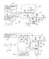
- FIG. 2 shows a preferred embodiment in which the discriminator circuit 16 contains two inductors 26 , 34 and two capacitors 28 , 30 .
- One of the inductors 26 is series resonant with the combination of a relatively small capacitor 30 to ground and the shunting capacitances of the piezoelectric transducers 18 , 20 at the transducer measurement frequency.
- the other inductor 34 is series resonant at the cleaning signal frequency with the relatively large capacitor 28 and all of the capacitances associated with that signal.
- FIG. 2 also shows protection diodes 22 , 24 , 25 , 27 used to protect the following receiving signal amplifiers 29 , 31 .
- the measurement signal source 12 is a model MAX 5048B supplied by the Maxim Corporation. In this embodiment it provides measurement signal acoustic bursts at about one MHz. Resonance at this frequency is obtained by choosing an inductor 26 having an inductance of ten microhenries and a capacitor 30 having a capacitance of 2.2 nanofarads. A few hundred picofarads of additional capacitance is typically associated with the transducers 18 , 20 .
- the cleaning signal source 14 is preferably at a ground state so that it does not have to disconnect from a potentially high voltage.
- this circuit arrangement is that with a relatively low resistance path in the series resonant circuit, and therefore high Q, the voltage appearing across the transducers can be much higher than the original measurement signal. For example, for a Q equal to ten, the transducer voltage is ten times that of the output from the measurement signal source 12 .
- the protective diodes 22 , 24 , 25 , 27 typically function to protect the following signal amplifiers 29 , 31 during the acoustic signal transmission and also during the cleaning operation.
- the shunt capacitor 30 effectively grounds one end (e.g., the top of the transducer symbol depicted in FIG. 2 ) of the transducers so that their other ends (e.g., the bottoms thereof) can provide signals to their respective amplifiers.
- the amplifiers 29 , 31 may be Intersil EL5263 dual op amps and are preferably of the current amplifying type having near zero input impedance.
- the negative inputs of the op amps are connected directly to the diodes and to gain-controlling feedback components (not shown) and the positive inputs are grounded.
- the amplifies can be connected through switches (not shown). Hence, the signal voltage across the diodes 22 , 24 , 25 , 27 is very low. The effect of these diodes on circuit operation during the time difference measurement of the acoustic signal is therefore negligible.
- a cleaning signal is supplied from another Maxim MAX 5049B source at a desired frequency of 50.8 kHz.
- the measurement signal source 12 is preferably at a ground state so that it does not have to disconnect from a potentially high voltage. This can be a large economic advantage because high voltage, high frequency switches are relatively uncommon and likely to be expensive.
- Another advantage of this arrangement is that with a relatively low resistance path in the resonant circuit, and therefore a high Q, the voltage appearing across the transducers can be much higher than the original cleaning signal as in the measurement description above.
- Yet another advantage of this arrangement is that the separation of the measurement and cleaning signal sources enables each source to be optimized for its unique function so that the cleaning signal source, for example, could thereby efficiently and economically provide a much higher magnitude signal.
- a relatively high cleaning voltage applied to the transducers is desirable when aggressive cavitation cleaning is to be carried out. In order to dislodge deposits, the acoustic windows may have to be displaced through a much larger amplitude than that used to make a flow rate measurement.
- transducers are usually optimized for the measurement function and are normally dimensioned to have a resonance peak at the measurement operating frequency.
- Transducer assemblies may also contain reactance and/or resonating elements to improve transducer efficiency and acoustic coupling to the fluid at the measurement frequency. While similar approaches may be utilized for cleaning assemblies of this sort the much lower operating frequency will be limiting. This limitation is compensated for at least in part, by the high cleaning voltage obtainable with the relative ease of the FIG. 2 configuration.
- piezoelectric transducers When operated at a frequency far below any of their mechanically resonant frequencies, as in a cleaning application of the sort described herein, piezoelectric transducers typically function electrically as capacitors of fair to medium Q (50 to 100).
- the inductors with which they resonate during cleaning can have similar Qs.
- the bandwidth of the resulting resonant circuits can be relatively small, 1 to 3% of the cleaning frequency for example, so that component values which result in a resonant frequency different from the design frequency because of manufacturing tolerances and drift, can seriously reduce the magnitude of the cleaning voltage applied to the transducers.
- This problem can be remedied by having the frequency of the cleaning signal controlled by the resonant circuit so that it always strives towards a maximum output exemplified by conventional LC feedback oscillators.
- the cleaning operation may also have a stabilizing effect on the measurement operation by enabling the transducer element surface in contact with its window to readjust that contact and recover from mechanical changes due to temperature changes, moisture absorption, aging effects etc. This recovery is facilitated when the transducer is pressed against its associated window as is the case when one uses thin windows in a pressured environment or provides a spring bias within the transducer assembly.
- FIG. 3 Another of many possible embodiments of the invention is depicted in FIG. 3 .
- the operating frequencies and component values can be the same as those of FIG. 2 .
- This embodiment is generally expected to have a somewhat lower power potential, when compared to the embodiment of FIG. 2 , even when a common amplifier 37 is used.
- the measurement 12 and cleaning 14 signal sources are switched by means of a switch 36 .
- the discriminator circuit 16 comprises several inductors 34 , 26 and capacitors 28 , 30 and is connected to the transducers 18 , 20 and their associated protective diodes 22 , 24 , 25 , 27 .
- a capacitor 28 couples the measurement signal to a series resonant circuit consisting of an inductor 26 , a shunting capacitor 30 and the shunting capacitance of the transducers 18 , 20 .
- the values of the inductor 34 and of the capacitor 28 are large enough so that they do not significantly affect the measurement operation.
- the switch 36 is controlled by the timing circuits 24 to connect the cleaning signal to the series resonant circuit, primarily consisting of a capacitor 28 and an inductor 34 , a shunt capacitor 30 and the shunting capacitance of the transducers 18 , 20 .
- the switch 36 of FIG. 3 switches low impedance loads, a relatively low voltage, high frequency switch is required. Components of this sort are readily available and relatively inexpensive. Alternatively, one can choose measurement and cleaning signal sources that provide low level signals to the switch 36 and then amplify the selected signals by a common amplifier 37 to provide the signals to the discriminator circuit.
- the common amplifier 37 needs to amplify the relatively high measurement frequency signals and can be a limiting factor on the power available for the cleaning function.
- FIG. 4 one finds another embodiment of circuitry of the invention.
- the operating frequencies and component values can be the same as those of FIG. 2 .
- the measurement signal from the measurement signal source 12 is supplied to a discriminator circuit 16 comprising two inductors 26 , 32 and two capacitors 28 , 30 .
- One of the inductors 26 has a relatively small inductance and is series resonant with a shunt capacitor 30 and the shunting capacitance of the piezoelectric transducers 18 , 20 at the transducer measurement frequency.
- the other inductor 34 is selected to have a relatively high inductance and is parallel resonant with capacitor 28 and with all other capacitances at the cleaning signal frequency.
- protective diodes 22 , 24 , 25 , 27 are used with following signal amplifiers 29 , 31 .
- the measurement signal is routed through an inductor 26 and a capacitor 28 to the transducers 18 , 20 .
- the cleaning signal source 14 controls a switching element, which is preferably an N-channel field effect transistor (FET) 40 , to switch into and out of its conductive state.
- the FET 40 is connected to the cathode of a diode 38 which has its anode connected to a high voltage signal junction supplying the transducers.
- the diode 38 by rectifying the signal when the FET 40 conducts, develops an oscillating voltage across the resonant circuit which adds a cleaning signal component to the measurement signal.
- the measurement signal circuit is still active during the cleaning phase although no meaningful flow rate output is available.
- the signal processor 22 may be programmed to suppress flow rate output during cleaning intervals.
- the cleaning signal component provided to the transducers which is available from the circuit of FIG. 4 has a magnitude approximately equal to that of the measurement signal source and is therefore limited in its cleaning ability when compared to the other methods described hereinbefore.
- the cleaning generator need only supply a low level signal, the other components are inexpensive and readily available so that this configuration could be attractive for some applications.
Landscapes
- Physics & Mathematics (AREA)
- Fluid Mechanics (AREA)
- General Physics & Mathematics (AREA)
- Electromagnetism (AREA)
- Measuring Volume Flow (AREA)
Abstract
Description
Claims (2)
Priority Applications (1)
| Application Number | Priority Date | Filing Date | Title |
|---|---|---|---|
| US11/958,403 US7684938B1 (en) | 2007-12-18 | 2007-12-18 | Self-cleaning ultrasonic flow sensor |
Applications Claiming Priority (1)
| Application Number | Priority Date | Filing Date | Title |
|---|---|---|---|
| US11/958,403 US7684938B1 (en) | 2007-12-18 | 2007-12-18 | Self-cleaning ultrasonic flow sensor |
Publications (1)
| Publication Number | Publication Date |
|---|---|
| US7684938B1 true US7684938B1 (en) | 2010-03-23 |
Family
ID=42027045
Family Applications (1)
| Application Number | Title | Priority Date | Filing Date |
|---|---|---|---|
| US11/958,403 Expired - Fee Related US7684938B1 (en) | 2007-12-18 | 2007-12-18 | Self-cleaning ultrasonic flow sensor |
Country Status (1)
| Country | Link |
|---|---|
| US (1) | US7684938B1 (en) |
Cited By (4)
| Publication number | Priority date | Publication date | Assignee | Title |
|---|---|---|---|---|
| US9192278B2 (en) | 2013-09-30 | 2015-11-24 | Elwha Llc | Self-cleaning substrate |
| WO2016176521A1 (en) * | 2015-04-29 | 2016-11-03 | Covidien Lp | Detection of malfunction of flow monitoring system of flow control apparatus |
| CN106643938A (en) * | 2017-01-03 | 2017-05-10 | 无锡水表有限责任公司 | Self-cleaning judgment method of intelligent ultrasonic water meter |
| EP3909693A1 (en) | 2020-05-15 | 2021-11-17 | Argo AI GmbH | Method for protecting an optical sensor of a vehicle from environmental pollutants |
Citations (6)
| Publication number | Priority date | Publication date | Assignee | Title |
|---|---|---|---|---|
| US4336719A (en) | 1980-07-11 | 1982-06-29 | Panametrics, Inc. | Ultrasonic flowmeters using waveguide antennas |
| US4601210A (en) | 1984-05-01 | 1986-07-22 | Manning Technologies, Inc. | Flowmeter with radial vibrational mode for ultrasonic waves |
| US5384029A (en) * | 1992-08-13 | 1995-01-24 | Campbell; Lawrence A. | Electrochemical membrane sensor |
| US6178827B1 (en) | 1999-04-22 | 2001-01-30 | Murray F. Feller | Ultrasonic flow sensor |
| US6422093B2 (en) | 1999-12-10 | 2002-07-23 | Murray Feller | Burst mode ultrasonic flow sensor |
| US6508134B1 (en) | 1999-09-01 | 2003-01-21 | Murray F. Feller | Transit-time flow sensor-frequency mode |
-
2007
- 2007-12-18 US US11/958,403 patent/US7684938B1/en not_active Expired - Fee Related
Patent Citations (6)
| Publication number | Priority date | Publication date | Assignee | Title |
|---|---|---|---|---|
| US4336719A (en) | 1980-07-11 | 1982-06-29 | Panametrics, Inc. | Ultrasonic flowmeters using waveguide antennas |
| US4601210A (en) | 1984-05-01 | 1986-07-22 | Manning Technologies, Inc. | Flowmeter with radial vibrational mode for ultrasonic waves |
| US5384029A (en) * | 1992-08-13 | 1995-01-24 | Campbell; Lawrence A. | Electrochemical membrane sensor |
| US6178827B1 (en) | 1999-04-22 | 2001-01-30 | Murray F. Feller | Ultrasonic flow sensor |
| US6508134B1 (en) | 1999-09-01 | 2003-01-21 | Murray F. Feller | Transit-time flow sensor-frequency mode |
| US6422093B2 (en) | 1999-12-10 | 2002-07-23 | Murray Feller | Burst mode ultrasonic flow sensor |
Cited By (7)
| Publication number | Priority date | Publication date | Assignee | Title |
|---|---|---|---|---|
| US9192278B2 (en) | 2013-09-30 | 2015-11-24 | Elwha Llc | Self-cleaning substrate |
| WO2016176521A1 (en) * | 2015-04-29 | 2016-11-03 | Covidien Lp | Detection of malfunction of flow monitoring system of flow control apparatus |
| US10066981B2 (en) | 2015-04-29 | 2018-09-04 | Kpr U.S., Llc | Detection of malfunction of flow monitoring system of flow control apparatus |
| CN106643938A (en) * | 2017-01-03 | 2017-05-10 | 无锡水表有限责任公司 | Self-cleaning judgment method of intelligent ultrasonic water meter |
| EP3909693A1 (en) | 2020-05-15 | 2021-11-17 | Argo AI GmbH | Method for protecting an optical sensor of a vehicle from environmental pollutants |
| US11596986B2 (en) | 2020-05-15 | 2023-03-07 | Argo Ai Gmbh | Method for protecting an optical sensor of a vehicle from environmental pollutants |
| US12030095B2 (en) | 2020-05-15 | 2024-07-09 | Ford Global Technologies, Llc | Method for protecting an optical sensor of a vehicle from environmental pollutants |
Similar Documents
| Publication | Publication Date | Title |
|---|---|---|
| US7764003B2 (en) | Signal control in micromachined ultrasonic transducer | |
| KR102746117B1 (en) | Plasma control device | |
| US7684938B1 (en) | Self-cleaning ultrasonic flow sensor | |
| US10473498B2 (en) | Electromagnetic flow meter including a function of measuring electrical conductivity of a fluid | |
| JP5135471B2 (en) | Full function test for in-situ testing of sensors and amplifiers | |
| WO2003011481A3 (en) | Micro-machined ultrasonic transducer (mut) having improved sensitivity | |
| CN109075760B (en) | Ultrasonic device, method of forming the same, and method of controlling the same | |
| CN111025034B (en) | Underwater electric field signal active detection circuit and detection method | |
| US4719409A (en) | Digital signal output capacitance sensor displacement gauging system | |
| KR102158040B1 (en) | Multiple frequency ultrasonic generator and frequency control method | |
| Zhao et al. | Capacitive micromachined ultrasonic transducers for transmitting and receiving ultrasound in air | |
| TWI550451B (en) | Control system and touch device | |
| US6748803B1 (en) | Liquid measurement system and shared interface apparatus for use therein | |
| Giribaldi et al. | Matching network-boosted 36% scaln pmut linear array | |
| CN106644044B (en) | High-frequency small-amplitude ultrasonic mechanical vibration wave power measuring method and device | |
| JP2002510044A (en) | Improved particle detector | |
| Yan et al. | An energy-efficient reconfigurable readout circuit for resonant sensors based on ring-down measurement | |
| US20210131862A1 (en) | Sensor device including a sensor for carrying out surrounding-area monitoring with the aid of sonic waves | |
| Ghasemi et al. | Real-time method for resonant frequency detection and excitation frequency tuning for piezoelectric ultrasonic transducers | |
| Davari et al. | Power converters design and analysis for high power piezoelectric ultrasonic transducers | |
| JP2008044304A (en) | Amperometry circuit of capacitive element, and failure detection device of piezoelectric head | |
| US6726626B1 (en) | Electric circuit for tuning a capactive electrostatic transducer | |
| JP2004113846A (en) | Oscillator for ultrasonic cleaning apparatus | |
| Mennicke et al. | Digitally Programmable low-noise Experimenter’s Platform for 300 kHz Ultrasonic Transducers | |
| US10763817B2 (en) | Characterization and driving method based on the second harmonic, which is enhancing the quality factor and reducing the feedthrough current in varying gap electrostatic MEMS resonators |
Legal Events
| Date | Code | Title | Description |
|---|---|---|---|
| FEPP | Fee payment procedure |
Free format text: PAT HOLDER NO LONGER CLAIMS SMALL ENTITY STATUS, ENTITY STATUS SET TO UNDISCOUNTED (ORIGINAL EVENT CODE: STOL); ENTITY STATUS OF PATENT OWNER: LARGE ENTITY |
|
| AS | Assignment |
Owner name: BABSON CAPITAL FINANCE, LLC, AS AGENT, ILLINOIS Free format text: SECURITY AGREEMENT;ASSIGNOR:ONICON INCORPORATED;REEL/FRAME:029564/0194 Effective date: 20121228 |
|
| AS | Assignment |
Owner name: ONICON INCORPORATED, FLORIDA Free format text: ASSIGNMENT OF ASSIGNORS INTEREST;ASSIGNOR:FELLER, MURRAY F.;REEL/FRAME:029564/0925 Effective date: 20121222 |
|
| FPAY | Fee payment |
Year of fee payment: 4 |
|
| AS | Assignment |
Owner name: BABSON CAPITAL FINANCE LLC, AS AGENT, ILLINOIS Free format text: AMENDED AND RESTATED PATENT SECURITY AGREEMENT;ASSIGNOR:ONICON INCORPORATED;REEL/FRAME:035496/0429 Effective date: 20150421 |
|
| AS | Assignment |
Owner name: BABSON CAPITAL FINANCE LLC, AS ADMINISTRATIVE AGEN Free format text: SECURITY INTEREST;ASSIGNOR:ONICON INCORPORATED;REEL/FRAME:038963/0873 Effective date: 20160610 |
|
| FEPP | Fee payment procedure |
Free format text: MAINTENANCE FEE REMINDER MAILED (ORIGINAL EVENT CODE: REM.) |
|
| LAPS | Lapse for failure to pay maintenance fees |
Free format text: PATENT EXPIRED FOR FAILURE TO PAY MAINTENANCE FEES (ORIGINAL EVENT CODE: EXP.) |
|
| STCH | Information on status: patent discontinuation |
Free format text: PATENT EXPIRED DUE TO NONPAYMENT OF MAINTENANCE FEES UNDER 37 CFR 1.362 |
|
| FP | Lapsed due to failure to pay maintenance fee |
Effective date: 20180323 |
|
| AS | Assignment |
Owner name: ONICON INCORPORATED, FLORIDA Free format text: RELEASE BY SECURED PARTY;ASSIGNOR:BABSON CAPITAL FINANCE LLC, AS ADMINISTRATIVE AGENT;REEL/FRAME:048980/0887 Effective date: 20190423 Owner name: ONICON INCORPORATED, FLORIDA Free format text: RELEASE BY SECURED PARTY;ASSIGNOR:BABSON CAPITAL FINANCE LLC, AS AGENT;REEL/FRAME:049042/0893 Effective date: 20190423 |