US7677758B2 - Display method and illumination system thereof - Google Patents
Display method and illumination system thereof Download PDFInfo
- Publication number
- US7677758B2 US7677758B2 US12/101,330 US10133008A US7677758B2 US 7677758 B2 US7677758 B2 US 7677758B2 US 10133008 A US10133008 A US 10133008A US 7677758 B2 US7677758 B2 US 7677758B2
- Authority
- US
- United States
- Prior art keywords
- light
- band
- light beam
- rectangular
- sub
- Prior art date
- Legal status (The legal status is an assumption and is not a legal conclusion. Google has not performed a legal analysis and makes no representation as to the accuracy of the status listed.)
- Expired - Fee Related, expires
Links
- 238000005286 illumination Methods 0.000 title claims abstract description 35
- 238000000034 method Methods 0.000 title claims description 21
- 230000003287 optical effect Effects 0.000 claims abstract description 36
- 238000009826 distribution Methods 0.000 claims description 16
- 230000003247 decreasing effect Effects 0.000 description 2
- 238000005516 engineering process Methods 0.000 description 2
- 238000012986 modification Methods 0.000 description 2
- 230000004048 modification Effects 0.000 description 2
- 230000008878 coupling Effects 0.000 description 1
- 238000010168 coupling process Methods 0.000 description 1
- 238000005859 coupling reaction Methods 0.000 description 1
Images


Classifications
-
- G—PHYSICS
- G03—PHOTOGRAPHY; CINEMATOGRAPHY; ANALOGOUS TECHNIQUES USING WAVES OTHER THAN OPTICAL WAVES; ELECTROGRAPHY; HOLOGRAPHY
- G03B—APPARATUS OR ARRANGEMENTS FOR TAKING PHOTOGRAPHS OR FOR PROJECTING OR VIEWING THEM; APPARATUS OR ARRANGEMENTS EMPLOYING ANALOGOUS TECHNIQUES USING WAVES OTHER THAN OPTICAL WAVES; ACCESSORIES THEREFOR
- G03B21/00—Projectors or projection-type viewers; Accessories therefor
- G03B21/14—Details
- G03B21/20—Lamp housings
-
- G—PHYSICS
- G02—OPTICS
- G02B—OPTICAL ELEMENTS, SYSTEMS OR APPARATUS
- G02B26/00—Optical devices or arrangements for the control of light using movable or deformable optical elements
- G02B26/08—Optical devices or arrangements for the control of light using movable or deformable optical elements for controlling the direction of light
- G02B26/10—Scanning systems
- G02B26/108—Scanning systems having one or more prisms as scanning elements
-
- G—PHYSICS
- G02—OPTICS
- G02B—OPTICAL ELEMENTS, SYSTEMS OR APPARATUS
- G02B27/00—Optical systems or apparatus not provided for by any of the groups G02B1/00 - G02B26/00, G02B30/00
- G02B27/09—Beam shaping, e.g. changing the cross-sectional area, not otherwise provided for
- G02B27/0905—Dividing and/or superposing multiple light beams
-
- G—PHYSICS
- G02—OPTICS
- G02B—OPTICAL ELEMENTS, SYSTEMS OR APPARATUS
- G02B27/00—Optical systems or apparatus not provided for by any of the groups G02B1/00 - G02B26/00, G02B30/00
- G02B27/10—Beam splitting or combining systems
- G02B27/1006—Beam splitting or combining systems for splitting or combining different wavelengths
- G02B27/102—Beam splitting or combining systems for splitting or combining different wavelengths for generating a colour image from monochromatic image signal sources
-
- G—PHYSICS
- G02—OPTICS
- G02B—OPTICAL ELEMENTS, SYSTEMS OR APPARATUS
- G02B27/00—Optical systems or apparatus not provided for by any of the groups G02B1/00 - G02B26/00, G02B30/00
- G02B27/10—Beam splitting or combining systems
- G02B27/12—Beam splitting or combining systems operating by refraction only
- G02B27/123—The splitting element being a lens or a system of lenses, including arrays and surfaces with refractive power
-
- G—PHYSICS
- G03—PHOTOGRAPHY; CINEMATOGRAPHY; ANALOGOUS TECHNIQUES USING WAVES OTHER THAN OPTICAL WAVES; ELECTROGRAPHY; HOLOGRAPHY
- G03B—APPARATUS OR ARRANGEMENTS FOR TAKING PHOTOGRAPHS OR FOR PROJECTING OR VIEWING THEM; APPARATUS OR ARRANGEMENTS EMPLOYING ANALOGOUS TECHNIQUES USING WAVES OTHER THAN OPTICAL WAVES; ACCESSORIES THEREFOR
- G03B21/00—Projectors or projection-type viewers; Accessories therefor
- G03B21/14—Details
- G03B21/20—Lamp housings
- G03B21/208—Homogenising, shaping of the illumination light
-
- H—ELECTRICITY
- H04—ELECTRIC COMMUNICATION TECHNIQUE
- H04N—PICTORIAL COMMUNICATION, e.g. TELEVISION
- H04N9/00—Details of colour television systems
- H04N9/12—Picture reproducers
- H04N9/31—Projection devices for colour picture display, e.g. using electronic spatial light modulators [ESLM]
- H04N9/3102—Projection devices for colour picture display, e.g. using electronic spatial light modulators [ESLM] using two-dimensional electronic spatial light modulators
- H04N9/3111—Projection devices for colour picture display, e.g. using electronic spatial light modulators [ESLM] using two-dimensional electronic spatial light modulators for displaying the colours sequentially, e.g. by using sequentially activated light sources
- H04N9/3117—Projection devices for colour picture display, e.g. using electronic spatial light modulators [ESLM] using two-dimensional electronic spatial light modulators for displaying the colours sequentially, e.g. by using sequentially activated light sources by using a sequential colour filter producing two or more colours simultaneously, e.g. by creating scrolling colour bands
Definitions
- the invention relates to a display method and an illumination system thereof, and more particularly to a display method and an illumination system which increases light usage.
- FIG. 1 shows an illumination system of a conventional projection device, wherein a plurality of spot light sources 11 , 12 and 13 provide a first light beam (blue) 1 , a second light beam (green) 2 and a third light beam (red) 3 .
- the first light beam (blue) 1 , the second light beam (green) 2 and the third light beam (red) 3 pass a scrolling element 14 to be scanned on a light valve 15 and mixed into white light beams.
- the first light beam (blue) 1 , the second light beam (green) 2 and the third light beam (red) 3 are spot light beams, and energy distributions thereof are in Gaussian distribution.
- a first overfill area 1 ′ surrounds the first light beam 1
- a second overfill area 2 ′ surrounds the second light beam 2
- a third overfill area 3 ′ surrounds the third light beam 3 .
- spokes 4 areas between the light beams (space areas and overfill areas) are defined as spokes 4 which are stopped by the light valve 15 .
- square measure of spoke 4 is large, and light usage is thus decreased.
- the invention provides a display method and an illumination system which increases light usage.
- an illumination system which provides a plurality of light beams to a light valve.
- the illumination system includes a plurality of light sources, a polynomial lens and an optical scanning element.
- the light sources are capable of emitting the light beams.
- the polynomial lens is disposed on light paths of the light beams and located between the light sources and the light valve, wherein the polynomial lens shapes the light beams into a plurality of rectangular light beams.
- the optical scanning element is disposed on light paths of the rectangular light beams and located between the polynomial lens and the light valve, wherein the optical scanning element is capable of moving for scanning the rectangular light beams on the light valve unidirectionally or back and forth along a direction, and the rectangular light beams partially overlap with each other on the light valve.
- a display method is provided. First, a polynomial lens, an optical scanning and a light valve are provided. Then, a first light source is provided, wherein the first light source provides a first light beam, the first light beam passes the polynomial lens to be shaped into a first rectangular light beam, and the first rectangular light beam passes the optical scanning element to be scanned on the light valve. Next, a second light source is provided, wherein the second light source provides a second light beam, the second light beam passes the polynomial lens to be shaped into a second rectangular light beam, the second rectangular light beam nears the first rectangular light beam, and the second rectangular light beam passes the optical scanning element to be scanned on the light valve.
- the polynomial lens is designed to make the first rectangular light beam partially overlap the second rectangular light beam on the light valve, and increase illumination areas of the first and second rectangular light beams.
- FIG. 1 schematically shows a conventional illumination system
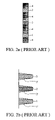
- FIG. 2 a shows valid illumination areas of the illumination system of FIG. 1 ;
- FIG. 2 b shows energy distribution of light beams in FIG. 2 a along a short axis
- FIG. 2 c shows energy distribution of light beams in FIG. 2 a along a long axis
- FIG. 2 d shows energy distribution of light beams in FIG. 2 a on the light valve
- FIG. 3 shows an illumination system of a first embodiment of the invention
- FIG. 4 shows a display method of an embodiment of the invention
- FIG. 5 a shows valid illumination areas of the illumination system of the first embodiment of the invention
- FIG. 5 b shows energy distribution of light beams of the first embodiment of the invention along a short axis
- FIG. 5 c shows energy distribution of light beams of the first embodiment of the invention along a long axis
- FIG. 5 d shows energy distribution of light beams of the first embodiment of the invention on the light valve
- FIG. 6 a shows valid illumination areas of the illumination system of a second embodiment of the invention.
- FIG. 6 b shows energy distribution of light beams of the second embodiment of the invention on the light valve.
- FIG. 3 shows an illumination system 100 of a first embodiment of the invention, which provides light beams 111 , 121 and 131 to a light valve 170 .
- the illumination system 100 includes a first light source (for example, blue light source) 110 , a second light source (for example, green light source) 120 , a third light source (for example, red light source) 130 , a polynomial lens 140 , a field lens 150 and an optical scanning element 160 .
- the first light source 110 is capable of emitting the first light beam 111 .
- the second light source 120 is capable of emitting the second light beam 121 .
- the third light source 130 is capable of emitting the third light beam 131 .
- the polynomial lens 140 is disposed on light paths of the light beams 111 , 121 and 131 and located between the light sources 110 , 120 and 130 and the light valve 170 to shape the light beams 111 , 121 , and 131 into rectangular light beams 112 , 122 and 132 .
- the field lens 150 and the optical scanning element 160 are disposed on light paths of the rectangular light beams 112 , 122 and 132 .
- the field lens 150 is located between the polynomial lens 140 and the optical scanning element 160
- the optical scanning element 160 is located between the polynomial lens 140 and the light valve 170 .
- the field lens 150 guides the rectangular light beams 112 , 122 and 132 into parallel light beams, and the rectangular light beams 112 , 122 and 132 travel from the field lens 150 to the optical scanning element 160 .
- the optical scanning element 160 is movable (rotatable), and scans the rectangular light beams 112 , 122 and 132 on the light valve 170 unidirectionally or back and forth along a direction A.
- the rectangular light beams 112 , 122 and 132 partially overlap with each other on the light valve 170 (with reference to FIG. 5 d ).
- the first light source 110 provides the first light beam 111
- the second light source 120 provides the second light beam 121
- the third light source 130 provides the third light beam 131 .
- the first light beam 111 passes the polynomial lens 140 to be shaped into the first rectangular light beam 112
- the second light beam 121 passes the polynomial lens 140 to be shaped into the second rectangular light beam 122
- the third light beam 131 passes the polynomial lens 140 to be shaped into the third rectangular light beam 132
- the first rectangular light beam 112 , the second rectangular light beam 122 and the third rectangular light beam 132 traveled from the polynomial lens 140 pass the field lens 150 , and are guided into parallel light beams by the field lens 150 , and are incident on the optical scanning element 160 to be scanned on the light valve 170 .
- the optical scanning element 160 reduces coherence of the first rectangular light beam 112 , the second rectangular light beam 122 and the third rectangular light beam 132 .
- the optical scanning element 160 may be a scrolling prism.
- the polynomial lens 140 may be a diffraction optical element or a free form surface lens.
- a and b are parameters.
- x, y and z are coordinates in an x-y-z coordinate system.
- the energy distributions of the first rectangular light beam 112 , the second rectangular light beam 122 and the third rectangular light beam 132 are approximately shaped into square waves.
- a diffuser may be disposed on a surface of the optical scanning element 160 to reduce coherence.
- FIG. 4 shows a display method of an embodiment of the invention.
- a polynomial lens, an optical scanning element and a light valve are provided (S 1 ).
- a first light source is provided, wherein the first light source provides a first light beam, the first light beam passes the polynomial lens to be shaped into a first rectangular light beam, and the first rectangular light beam passes the optical scanning element to be scanned on the light valve (S 2 ).
- a second light source wherein the second light source provides a second light beam, the second light beam passes the polynomial lens to be shaped into a second rectangular light beam, the second rectangular light beam nears the first rectangular light beam, and the second rectangular light beam passes the optical scanning element to be scanned on the light valve (S 3 ).
- a third light source is provided, wherein the third light source provides a third light beam, the third light beam passes the polynomial lens to be shaped into a third rectangular light beam, the third rectangular light beam nears the second rectangular light beam, and the third rectangular light beam passes the optical scanning element to be scanned on the light valve (S 4 ).
- the polynomial lens is designed to make the first, second and third rectangular light beams partially overlap with each other on the light valve (S 5 ).
- FIG. 5 a shows valid illumination areas of the illumination system of the first embodiment of the invention.
- FIG. 5 b shows energy distribution of light beams of the first embodiment of the invention along a short axis.
- FIG. 5 c shows energy distribution of light beams of the first embodiment of the invention along a long axis.
- FIG. 5 d shows energy distribution of light beams of the first embodiment of the invention on the light valve.
- the first rectangular light beam 112 forms a first main-band 113 and two first sub-bands 113 ′ on the light valve.
- the first sub-bands 113 ′ are located on two sides on the first main-band 113 respectively.
- the second rectangular light beam 122 forms a second main-band 123 and two second sub-bands 123 ′ on the light valve.
- the second sub-bands 123 ′ are located on two sides on the second main-band 123 respectively.
- the third rectangular light beam 132 forms a third main-band 133 and two third sub-bands 133 ′ on the light valve.
- the third sub-bands 133 ′ are located on two sides on the third main-band 133 respectively.
- the first sub-band 113 ′ partially overlaps the second sub-band 123 ′ next thereto.
- the second sub-band 123 ′ overlaps the third sub-band 133 ′ next thereto.
- the first sub-band 113 ′ totally overlaps the second sub-band 123 ′ next thereto.
- the second sub-band 123 ′ totally overlaps the third sub-band 133 ′ next thereto.
- the first sub-bands 113 ′, the second sub-bands 123 ′ and the third sub-bands 133 ′ are overfill areas.
- energy distributions of the first rectangular light beam 112 , the second rectangular light beam 122 and the third rectangular light beam 132 approximate to square waves. Therefore, with reference to FIGS.
- the first main-band 113 , the second main-band 123 and the third main-band 133 provide uniformed illumination with increased valid illumination areas. There is no space area between the main-band and the sub-band next thereto. Areas where the sub-bands overlap with each other are defined as spokes 4 .
- the spokes 4 are stopped by the light valve. In the embodiment of the invention, square measure of the spokes 4 is reduced, useless area on the light valve is reduced, and light usage is increased.
- FIG. 6 a shows valid illumination areas of the illumination system of a second embodiment of the invention
- FIG. 6 b shows energy distribution of light beams of the second embodiment of the invention on the light valve.
- the design of polynomial lens is designed to further increase square measure of the main-bands and overlap other main-bands next thereto.
- the first main-band 113 partially overlaps the second main-band 123 to form a mixed main-band 181 .
- the first main-band 113 is a blue light strap
- the second main-band 123 is a green light strap
- the mixed main-band 181 is a cyan light strap.
- the second main-band 123 partially overlaps the third main-band 133 to form a mixed main-band 182 .
- the third main-band 133 is a red light strap
- the mixed main-band 182 is a yellow light strap. Areas where the sub-bands overlap the main-bands are defined as spokes 4 .
- image process technology for example, Brilliantcolor
- the light beams passing the polynomial lens are shaped into rectangular light beams with increased valid illumination square measure.
- the rectangular light beams are scanned to the light valve by the optical scanning element, wherein the rectangular light beams overlap with each other.
- Square measure of the spokes 4 is reduced, useless area on the light valve is reduced, and light usage is increased. Additionally, color harmony is also improved.
Landscapes
- Physics & Mathematics (AREA)
- General Physics & Mathematics (AREA)
- Optics & Photonics (AREA)
- Engineering & Computer Science (AREA)
- Multimedia (AREA)
- Signal Processing (AREA)
- Mechanical Optical Scanning Systems (AREA)
Abstract
Description
sag: z=a 2 *x 2 +a 4 *x 4 +a 6 *x 6 +a 8 +x 8 *b 2 *y 2 +b 4 *y 4 +b 6 *y 6 +b 8 *y 8
Claims (20)
Applications Claiming Priority (3)
| Application Number | Priority Date | Filing Date | Title |
|---|---|---|---|
| TW96146488A | 2007-12-06 | ||
| TW096146488A TW200925764A (en) | 2007-12-06 | 2007-12-06 | Display method and illumination system thereof |
| TW96146488 | 2007-12-06 |
Publications (2)
| Publication Number | Publication Date |
|---|---|
| US20090147514A1 US20090147514A1 (en) | 2009-06-11 |
| US7677758B2 true US7677758B2 (en) | 2010-03-16 |
Family
ID=40721470
Family Applications (1)
| Application Number | Title | Priority Date | Filing Date |
|---|---|---|---|
| US12/101,330 Expired - Fee Related US7677758B2 (en) | 2007-12-06 | 2008-04-11 | Display method and illumination system thereof |
Country Status (2)
| Country | Link |
|---|---|
| US (1) | US7677758B2 (en) |
| TW (1) | TW200925764A (en) |
Cited By (1)
| Publication number | Priority date | Publication date | Assignee | Title |
|---|---|---|---|---|
| TWI495906B (en) * | 2013-10-24 | 2015-08-11 | Hon Hai Prec Ind Co Ltd | A freeform surface lens and imaging system including the same |
Citations (8)
| Publication number | Priority date | Publication date | Assignee | Title |
|---|---|---|---|---|
| US4826290A (en) | 1987-09-21 | 1989-05-02 | Hughes Aircraft Company | Method of producing stable holograms in dichromatic gelatin |
| US5548347A (en) * | 1990-12-27 | 1996-08-20 | Philips Electronics North America Corporation | Single panel color projection video display having improved scanning |
| US6282031B1 (en) | 1996-05-14 | 2001-08-28 | Asahi Kogaku Kogyo Kabushiki Kaisha | Beam shaping optical system |
| US6493149B2 (en) | 2001-04-27 | 2002-12-10 | Hitachi, Ltd. | Optical unit and image display device thereof |
| TW541834B (en) | 2001-11-16 | 2003-07-11 | Ind Tech Res Inst | Laser projector |
| US6967777B2 (en) | 2004-03-10 | 2005-11-22 | Sumitomo Electric Industries, Ltd. | Superposing diffraction optical element homogenizer optical system |
| US20060209310A1 (en) | 2004-12-22 | 2006-09-21 | Holger Muenz | Optical illumination system for creating a line beam |
| US7390093B2 (en) * | 2005-02-18 | 2008-06-24 | Intel Corporation | Projection display with color segmented microdisplay panel |
Family Cites Families (1)
| Publication number | Priority date | Publication date | Assignee | Title |
|---|---|---|---|---|
| US6262031B1 (en) * | 1999-03-12 | 2001-07-17 | Merck & Co., Inc. | Method for treating pediculosis capitisinfestation |
-
2007
- 2007-12-06 TW TW096146488A patent/TW200925764A/en unknown
-
2008
- 2008-04-11 US US12/101,330 patent/US7677758B2/en not_active Expired - Fee Related
Patent Citations (8)
| Publication number | Priority date | Publication date | Assignee | Title |
|---|---|---|---|---|
| US4826290A (en) | 1987-09-21 | 1989-05-02 | Hughes Aircraft Company | Method of producing stable holograms in dichromatic gelatin |
| US5548347A (en) * | 1990-12-27 | 1996-08-20 | Philips Electronics North America Corporation | Single panel color projection video display having improved scanning |
| US6282031B1 (en) | 1996-05-14 | 2001-08-28 | Asahi Kogaku Kogyo Kabushiki Kaisha | Beam shaping optical system |
| US6493149B2 (en) | 2001-04-27 | 2002-12-10 | Hitachi, Ltd. | Optical unit and image display device thereof |
| TW541834B (en) | 2001-11-16 | 2003-07-11 | Ind Tech Res Inst | Laser projector |
| US6967777B2 (en) | 2004-03-10 | 2005-11-22 | Sumitomo Electric Industries, Ltd. | Superposing diffraction optical element homogenizer optical system |
| US20060209310A1 (en) | 2004-12-22 | 2006-09-21 | Holger Muenz | Optical illumination system for creating a line beam |
| US7390093B2 (en) * | 2005-02-18 | 2008-06-24 | Intel Corporation | Projection display with color segmented microdisplay panel |
Cited By (1)
| Publication number | Priority date | Publication date | Assignee | Title |
|---|---|---|---|---|
| TWI495906B (en) * | 2013-10-24 | 2015-08-11 | Hon Hai Prec Ind Co Ltd | A freeform surface lens and imaging system including the same |
Also Published As
| Publication number | Publication date |
|---|---|
| US20090147514A1 (en) | 2009-06-11 |
| TW200925764A (en) | 2009-06-16 |
Similar Documents
| Publication | Publication Date | Title |
|---|---|---|
| US10310257B2 (en) | Head-up display device | |
| JP4114173B1 (en) | Display device and lighting device | |
| US8416363B2 (en) | Liquid crystal display backlight device and liquid crystal display | |
| CN100487561C (en) | Image display apparatus | |
| KR101297890B1 (en) | Light source device and projector | |
| CN103827572B (en) | Light intensity distribution conversion element, planar light source device, and liquid crystal display device | |
| US7077546B2 (en) | Illumination apparatus and liquid crystal projector using the illumination apparatus | |
| US8840251B2 (en) | Light collecting optical system and projection-type image display apparatus | |
| US9447947B2 (en) | Illumination device having primary light unit and phosphor element | |
| US20150160394A1 (en) | Planar light source device and liquid crystal display device | |
| CN103370569B (en) | Surface light source device and liquid crystal display device | |
| CN119225107B (en) | Laser projection light source and laser projection equipment | |
| US20160320541A1 (en) | Backlight module and display device | |
| JP2012186049A (en) | Illumination device and image display device using the same | |
| JP6292376B2 (en) | Vehicle lamp and lens body | |
| US20200400299A1 (en) | Light source system and lighting device | |
| US7677758B2 (en) | Display method and illumination system thereof | |
| US20050036120A1 (en) | Projector optical unit, projection type image display apparatus, and rear projection type image display apparatus | |
| JP4356095B1 (en) | Liquid crystal display device and lighting device | |
| CN119045269A (en) | Illumination system and projection apparatus | |
| JP2010020920A (en) | Linear light source device and image reading device | |
| US20100277949A1 (en) | Light guide plate and backlight module | |
| JP2010170755A (en) | Planar light-emitting device and image display | |
| KR101101792B1 (en) | LCD and lighting device | |
| CN119045268B (en) | Illumination system and projection apparatus |
Legal Events
| Date | Code | Title | Description |
|---|---|---|---|
| AS | Assignment |
Owner name: YOUNG OPTICS INC., TAIWAN Free format text: ASSIGNMENT OF ASSIGNORS INTEREST;ASSIGNORS:CHENG, CHU-MING;WU, SHANG-YI;CHEN, TIEN-PAO;REEL/FRAME:020789/0342 Effective date: 20080327 Owner name: YOUNG OPTICS INC.,TAIWAN Free format text: ASSIGNMENT OF ASSIGNORS INTEREST;ASSIGNORS:CHENG, CHU-MING;WU, SHANG-YI;CHEN, TIEN-PAO;REEL/FRAME:020789/0342 Effective date: 20080327 |
|
| FPAY | Fee payment |
Year of fee payment: 4 |
|
| FEPP | Fee payment procedure |
Free format text: MAINTENANCE FEE REMINDER MAILED (ORIGINAL EVENT CODE: REM.) |
|
| LAPS | Lapse for failure to pay maintenance fees |
Free format text: PATENT EXPIRED FOR FAILURE TO PAY MAINTENANCE FEES (ORIGINAL EVENT CODE: EXP.) |
|
| STCH | Information on status: patent discontinuation |
Free format text: PATENT EXPIRED DUE TO NONPAYMENT OF MAINTENANCE FEES UNDER 37 CFR 1.362 |
|
| FP | Lapsed due to failure to pay maintenance fee |
Effective date: 20180316 |