US7673665B2 - Cordless flexible window covering - Google Patents
Cordless flexible window covering Download PDFInfo
- Publication number
- US7673665B2 US7673665B2 US11/781,981 US78198107A US7673665B2 US 7673665 B2 US7673665 B2 US 7673665B2 US 78198107 A US78198107 A US 78198107A US 7673665 B2 US7673665 B2 US 7673665B2
- Authority
- US
- United States
- Prior art keywords
- window covering
- flange
- motor
- stiffener
- rail
- Prior art date
- Legal status (The legal status is an assumption and is not a legal conclusion. Google has not performed a legal analysis and makes no representation as to the accuracy of the status listed.)
- Active, expires
Links
Images


Classifications
-
- E—FIXED CONSTRUCTIONS
- E06—DOORS, WINDOWS, SHUTTERS, OR ROLLER BLINDS IN GENERAL; LADDERS
- E06B—FIXED OR MOVABLE CLOSURES FOR OPENINGS IN BUILDINGS, VEHICLES, FENCES OR LIKE ENCLOSURES IN GENERAL, e.g. DOORS, WINDOWS, BLINDS, GATES
- E06B9/00—Screening or protective devices for wall or similar openings, with or without operating or securing mechanisms; Closures of similar construction
- E06B9/24—Screens or other constructions affording protection against light, especially against sunshine; Similar screens for privacy or appearance; Slat blinds
- E06B9/26—Lamellar or like blinds, e.g. venetian blinds
- E06B9/262—Lamellar or like blinds, e.g. venetian blinds with flexibly-interconnected horizontal or vertical strips; Concertina blinds, i.e. upwardly folding flexible screens
- E06B2009/2622—Gathered vertically; Roman, Austrian or festoon blinds
-
- E—FIXED CONSTRUCTIONS
- E06—DOORS, WINDOWS, SHUTTERS, OR ROLLER BLINDS IN GENERAL; LADDERS
- E06B—FIXED OR MOVABLE CLOSURES FOR OPENINGS IN BUILDINGS, VEHICLES, FENCES OR LIKE ENCLOSURES IN GENERAL, e.g. DOORS, WINDOWS, BLINDS, GATES
- E06B9/00—Screening or protective devices for wall or similar openings, with or without operating or securing mechanisms; Closures of similar construction
- E06B9/24—Screens or other constructions affording protection against light, especially against sunshine; Similar screens for privacy or appearance; Slat blinds
- E06B9/26—Lamellar or like blinds, e.g. venetian blinds
- E06B9/28—Lamellar or like blinds, e.g. venetian blinds with horizontal lamellae, e.g. non-liftable
- E06B9/30—Lamellar or like blinds, e.g. venetian blinds with horizontal lamellae, e.g. non-liftable liftable
- E06B9/32—Operating, guiding, or securing devices therefor
- E06B9/322—Details of operating devices, e.g. pulleys, brakes, spring drums, drives
- E06B2009/3222—Cordless, i.e. user interface without cords
Definitions
- the invention relates generally to cordless window coverings and more particularly to cordless window coverings having relatively soft, flexible panels.
- Cordless window coverings typically comprise a spring motor connected to the top or bottom of the window covering.
- the spring motor offsets the weight of the shade panel to hold the shade panel in any vertical position.
- a user pushes up or pulls down on the bottom rail (or top rail in the case of a top down shade) of the shade panel to raise or lower the shade.
- the spring motor assists in the raising of the shade panel and holds the shade panel in the desired position.
- the shade panels in cordless window coverings are comprised of cellular shades.
- a window covering comprises a flexible panel having a top edge and a bottom edge. At least one lift cord is provided for raising and lowering the bottom edge. Each lift cord is connected to one end of a stiffener at a first point and the opposite end of the stiffener is connected to approximately the bottom edge of the flexible panel. The stiffener prevents the folding of the flexible panel between the bottom edge and the first point.
- the top edge may be connected to a head rail and the bottom edge may be connected to a bottom rail.
- a motor may be located adjacent the top rail where the lift cord is connected to the motor.
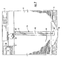
- FIG. 1 is a perspective back view of an embodiment of the window covering of the invention.
- FIG. 2 is a perspective view showing the spring motor mounted on an embodiment of the window covering of the invention.
- FIG. 3 is a perspective view showing the spring motor and an embodiment of a mounting bracket of the invention.
- FIG. 4 is a front view showing the mounting bracket of FIG. 3 .
- FIG. 5 is a perspective side view showing the mounting bracket of FIG. 3 .
- FIG. 6 is a partial back view showing an embodiment of the window covering of the invention.
- FIG. 7 is a partial back view showing an embodiment of the stiffener used in the window covering of the invention.
- FIG. 8 is a perspective view showing an embodiment of the stiffener used in the window covering of the invention.
- FIGS. 9 and 10 are detailed views of an embodiment of the stiffener of the invention.
- FIG. 11 is a partial front view showing an embodiment of the handle mounted on the shade panel.
- FIG. 12 is a partial perspective side view of an embodiment of the window covering of the invention showing the bottom rail.
- the window covering is shown generally at 1 in the drawings and comprises a head rail 2 supporting a flexible shade panel 4 that has a bottom rail 6 located at the lower edge of the panel 4 .
- the front of the head rail 2 is covered by the shade panel 4 such that it is hidden from view when the window covering is viewed from the front.
- the bottom rail 6 may be covered in the shade panel fabric such that it is hidden from view.
- the flexible shade panel 4 may comprise woven wood shades, natural shades, Roman shades, hobbled shades, looped shades, or the like where the shade panel is made of a relatively flexible material.
- the head rail 2 and shade panel 4 are typically dimensioned to coincide with the dimensions of the architectural feature with which the window covering is intended to be used. While the invention is referred to as a window covering and may be used primarily to cover windows, it is to be understood that the invention may be used to cover any architectural feature such as a window, door, opening, alcove or the like.
- the upper end of the panel 4 is secured to the head rail 2 such that the head rail extends for substantially the width of the panel.
- the head rail 2 may comprise a rigid material such as a wood or metal member and may be formed as a solid member as shown or may be formed as hollow or U-shaped member.
- a spring motor 8 such as described in U.S. Pat. No. 6,149,094, dated Nov. 21, 2000 and U.S. Pat. No. 6,318,661, dated Nov. 20, 2001, which are incorporated in their entirety by reference herein, is mounted to the head rail 2 .
- Lift cords 10 and 12 extend from the spring motor 8 to stiffeners 14 .
- Stiffeners 14 are connected to the bottom rail 6 of the shade panel 4 as will hereinafter be explained.
- Spring motor 8 assists in the raising of the shade panel 4 and serves to hold the shade panel 4 in any desired raised position. While the illustrated embodiment shows a single spring motor connected to two lift cords, a greater number of lift cords and spring motors may be used depending upon the size, weight and geometry of the window covering.
- the lift cords may pass through pulleys 16 and 18 that are connected to the head rail 2 to space the lift cords a desired distance on the shade panel and to facilitate the lifting of the shade.
- a spring motor support 20 attaches the spring motor 8 to the headrail 2 .
- support 20 includes a back flange 22 having first and second flanges 24 and 26 extending thereform. Flanges 24 and 26 are spaced and dimensioned to receive the headrail 2 therebetween.
- a motor support flange 28 extends from back flange 22 to the side opposite flanges 24 and 26 and defines a support surface on which spring motor 8 rests. Flange 28 may include upwardly extending flanges 30 and 32 for engaging the spring motor.
- a locking element 34 is formed in the back flange 22 for gripping the upper end of the spring motor to maintain the motor on the support.
- the motor support 20 is made of a flexible material such as plastic such that the support can flex to allow the motor to be snapped into the support.
- the support includes apertures 36 for receiving fasters such as screws or rivets for securing the support to the head rail 2 .
- a device for stiffening the bottom of panel 4 in order to help with the control of the bottom of the shade during the raising and lowering of the shade is provided.
- the stiffener 14 comprises a rigid member connected between the bottom rail 6 and each of the lift cords 10 and 12 that extend from the spring motor 8 . At least the upper edge 14 a of the stiffener 14 is connected to panel 4 .
- the stiffener 14 helps transfer the motion of the lifting of the bottom of the shade through the entire bottom panel therefore helping control the fabric while the shade is being raised.
- the stiffener 14 comprises an elongated member 40 that extends generally parallel to lift cords 10 and 12 .
- the elongated member 40 includes a first upper eyelet 42 and a second lower eyelet 44 .
- Each lift cord extends through the upper eyelet 42 and is attached to the stiffener 14 at the lower eyelet 44 .
- the lift cord is tied to the eyelet 44 although the lift cord may be secured to the stiffener 14 by any mechanism.
- the elongated member 40 terminates in a sleeve 48 that has an internal shape and dimension to receive the bottom rail.
- the bottom rail has a circular cross-section such that the sleeve 48 defines a generally cylindrical internal cavity 50 .
- the bottom rail may have other cross-sectional shapes and the internal cavity 50 would be shaped to match the shape of the bottom rail.
- the sleeve 48 may be slipped over the bottom rail and includes a gap 52 to allow the sleeve 48 to flex to accept the bottom rail.
- a handle support member 54 is provided for supporting a handle 56 on the bottom rail.
- the support member 54 is spaced from the sleeve a distance sufficient to allow the handle 56 and panel material to fit between the support member 54 and sleeve 48 .
- the support member 54 may be attached to the handle by a fastener that engages aperture 58 and is secured to the bottom rail.
- the stiffener 14 (and handle 56 ) can slide onto the shade after the shade is made and secured thereto by a fastener such as a screw, rivet or adhesive.
- Use of the handle support member 54 allows the handle 56 to be supported on the bottom rail without any visible fasteners showing on the front of the window covering as shown in FIG. 11 .
- the bottom rail includes a rigid member 60 that extends for substantially the entire width of the panel.
- the member 60 has a circular profile although the member may have any cross-sectional shape.
- Separate weights 62 may be attached to the bottom rail 6 where the member 60 has longitudinally extending grooves 64 that receive long extruded weights 62 such that the member 60 and weights 62 can be wrapped in the shade panel fabric.
- the weights 62 may be added to balance the weight of the relatively light flexible panel against the lift force generated by the spring motor 8 depending upon the weight of the flexible panel and the force generated by the spring motor.
- the weight may also be generated by the bottom rail itself.
- the user grasps the bottom rail/handle and exerts either an upward force to raise the panel or a downward force to lower the panel.
- the use of the stiffeners 14 balances the forces on each of the lift cords.
- the stiffeners prevent the portion of the panel 4 between the end of the stiffener and the bottom rail (or the top rail in the case of a top down shade) from folding.
- the stiffeners allow the relatively soft and flexible panel fabric above the stiffeners to fold and drape in a controlled and aesthetically pleasing manner as the bottom rail is raised as shown in FIGS. 1 and 17 . Without the stiffeners the flexible panel material would tend to fall below the bottom rail in an uncontrolled manner as the window covering is raised making it difficult for the user to hold and manipulate the bottom rail. Moreover, without the stiffeners the panel will not fold and drape in a controlled and aesthetically pleasing manner.
- the stiffeners 14 can also be used on the top edge of a panel of a window covering that is a “top down” or a “top down/bottom up” shade to control the movement of the top of the shade.
- Top down shades are shades where top of the shade panel may be raised and lowered.
- the cordless shade can also be made by attaching the motor 8 to the bottom of the shade panel and adding a braking mechanism so that the shade can be raised when the braking mechanism is released.
- the stiffeners 14 can be slid onto the bottom rail 6 and the fabric can be wrapped around both the rail and the stiffener. This gives the flexibility to add different handles to the shade.
- the stiffeners 14 can also slide over the fabric and bottom bar after the bottom bar has been wrapped with the fabric.
Landscapes
- Engineering & Computer Science (AREA)
- Structural Engineering (AREA)
- Architecture (AREA)
- Civil Engineering (AREA)
- Curtains And Furnishings For Windows Or Doors (AREA)
- Window Of Vehicle (AREA)
Abstract
Description
Claims (15)
Priority Applications (4)
| Application Number | Priority Date | Filing Date | Title |
|---|---|---|---|
| US11/781,981 US7673665B2 (en) | 2007-01-19 | 2007-07-24 | Cordless flexible window covering |
| CA2618842A CA2618842C (en) | 2007-01-19 | 2008-01-16 | Cordless flexible window covering |
| MX2008000880A MX2008000880A (en) | 2007-01-19 | 2008-01-18 | Cordless flexible window covering. |
| CN200810000547.6A CN101205792B (en) | 2007-01-19 | 2008-01-21 | Cordless flexible window covering |
Applications Claiming Priority (2)
| Application Number | Priority Date | Filing Date | Title |
|---|---|---|---|
| US88133107P | 2007-01-19 | 2007-01-19 | |
| US11/781,981 US7673665B2 (en) | 2007-01-19 | 2007-07-24 | Cordless flexible window covering |
Publications (2)
| Publication Number | Publication Date |
|---|---|
| US20080173412A1 US20080173412A1 (en) | 2008-07-24 |
| US7673665B2 true US7673665B2 (en) | 2010-03-09 |
Family
ID=39566244
Family Applications (1)
| Application Number | Title | Priority Date | Filing Date |
|---|---|---|---|
| US11/781,981 Active 2028-01-21 US7673665B2 (en) | 2007-01-19 | 2007-07-24 | Cordless flexible window covering |
Country Status (3)
| Country | Link |
|---|---|
| US (1) | US7673665B2 (en) |
| CN (1) | CN101205792B (en) |
| MX (1) | MX2008000880A (en) |
Cited By (16)
| Publication number | Priority date | Publication date | Assignee | Title |
|---|---|---|---|---|
| US20110067820A1 (en) * | 2009-09-22 | 2011-03-24 | Kai-Sheng Hsu | Roman Shade Window Curtain Having A Special Head Rail For Using A Roller Shade As Its Release/Retraction Control |
| US20110067819A1 (en) * | 2009-09-24 | 2011-03-24 | K.E. & Kingstone Co., Ltd. | Curtain |
| US20110203079A1 (en) * | 2008-08-22 | 2011-08-25 | Anthony James M | System for confining lift cords in coverings for architectural openings |
| US20110232852A1 (en) * | 2009-11-02 | 2011-09-29 | David Perkowitz | Window Shade and Method of Use Thereof |
| US20130020034A1 (en) * | 2011-07-19 | 2013-01-24 | David Perkowitz | Window shade |
| US8365795B2 (en) | 2009-11-02 | 2013-02-05 | Horizons Window Fashions, Inc. | Window shade and method of use thereof |
| US8505607B2 (en) | 2011-07-19 | 2013-08-13 | Horizons Window Fashions, Inc. | Window shade |
| US8857493B2 (en) * | 2011-06-10 | 2014-10-14 | Horizons Holdings, Llc | Window shade and method of use thereof |
| US9010399B2 (en) | 2012-05-01 | 2015-04-21 | Horizons Holdings, Llc | Window shade |
| US20160017656A1 (en) * | 2013-03-15 | 2016-01-21 | Springs Window Fashions, Llc | Window covering motorized lift and control operating system |
| USD758759S1 (en) * | 2013-07-23 | 2016-06-14 | Hunter Douglas Inc. | Handle for a window covering |
| US9470040B2 (en) | 2014-04-08 | 2016-10-18 | David R. Hall | Pull cord for controlling a window covering |
| US9489834B2 (en) | 2014-04-08 | 2016-11-08 | David R. Hall | Noise-reducing motorized gearbox assembly for automating window coverings |
| US20170067286A1 (en) * | 2014-04-08 | 2017-03-09 | David R. Hall | Motorized Gearbox Assembly with Through-Channel Design |
| US10851587B2 (en) | 2016-10-19 | 2020-12-01 | Hunter Douglas Inc. | Motor assemblies for architectural coverings |
| US11486198B2 (en) | 2019-04-19 | 2022-11-01 | Hunter Douglas Inc. | Motor assemblies for architectural coverings |
Families Citing this family (1)
| Publication number | Priority date | Publication date | Assignee | Title |
|---|---|---|---|---|
| US9322210B2 (en) * | 2013-08-19 | 2016-04-26 | Comfortex Window Fashions | Cordless fabric venetian window shade assembly |
Citations (8)
| Publication number | Priority date | Publication date | Assignee | Title |
|---|---|---|---|---|
| US5566736A (en) | 1995-11-13 | 1996-10-22 | Crider; Grant W. | Sealable curtain |
| US5785105A (en) | 1995-11-13 | 1998-07-28 | Crider; Grant W. | Sealable curtain |
| US20040060670A1 (en) | 2002-09-27 | 2004-04-01 | Ren Judkins | Roll-up shade with cord capture |
| US6769471B2 (en) | 1999-01-12 | 2004-08-03 | Newell Window Furnishings Inc. | Bottom rail weight and balancing system |
| US20060102293A1 (en) * | 2004-11-12 | 2006-05-18 | Wen-Te Wu | Foldable window blind |
| US7086446B2 (en) | 2003-12-30 | 2006-08-08 | Lumino, Inc. | Breakaway cord system for roll-up shades |
| US20080149284A1 (en) * | 2006-12-20 | 2008-06-26 | Ya-Yin Lin | Blind device |
| US20080179016A1 (en) * | 2007-01-25 | 2008-07-31 | Ya-Yin Lin | Blind device |
Family Cites Families (2)
| Publication number | Priority date | Publication date | Assignee | Title |
|---|---|---|---|---|
| CN2032646U (en) * | 1988-04-08 | 1989-02-15 | 天津轻工业学院 | Shutter curtain |
| CN1054526A (en) * | 1990-03-05 | 1991-09-18 | 赵晓光 | Vertical automatic curtain folding and unfolding and direction changing device |
-
2007
- 2007-07-24 US US11/781,981 patent/US7673665B2/en active Active
-
2008
- 2008-01-18 MX MX2008000880A patent/MX2008000880A/en active IP Right Grant
- 2008-01-21 CN CN200810000547.6A patent/CN101205792B/en active Active
Patent Citations (8)
| Publication number | Priority date | Publication date | Assignee | Title |
|---|---|---|---|---|
| US5566736A (en) | 1995-11-13 | 1996-10-22 | Crider; Grant W. | Sealable curtain |
| US5785105A (en) | 1995-11-13 | 1998-07-28 | Crider; Grant W. | Sealable curtain |
| US6769471B2 (en) | 1999-01-12 | 2004-08-03 | Newell Window Furnishings Inc. | Bottom rail weight and balancing system |
| US20040060670A1 (en) | 2002-09-27 | 2004-04-01 | Ren Judkins | Roll-up shade with cord capture |
| US7086446B2 (en) | 2003-12-30 | 2006-08-08 | Lumino, Inc. | Breakaway cord system for roll-up shades |
| US20060102293A1 (en) * | 2004-11-12 | 2006-05-18 | Wen-Te Wu | Foldable window blind |
| US20080149284A1 (en) * | 2006-12-20 | 2008-06-26 | Ya-Yin Lin | Blind device |
| US20080179016A1 (en) * | 2007-01-25 | 2008-07-31 | Ya-Yin Lin | Blind device |
Cited By (35)
| Publication number | Priority date | Publication date | Assignee | Title |
|---|---|---|---|---|
| US8474507B2 (en) | 2008-08-22 | 2013-07-02 | Hunter Douglas Inc. | System for confining lift cords in coverings for architectural openings |
| US9222303B2 (en) | 2008-08-22 | 2015-12-29 | Hunter Douglas Inc. | System for confining lift cords in coverings for architectural openings |
| US20110203079A1 (en) * | 2008-08-22 | 2011-08-25 | Anthony James M | System for confining lift cords in coverings for architectural openings |
| US8783330B2 (en) | 2008-08-22 | 2014-07-22 | Hunter Douglas Inc. | System for confining lift cords in coverings for architectural openings |
| US8267144B2 (en) * | 2009-09-22 | 2012-09-18 | Pacific Heritage Home Fashions Inc. | Roman shade window curtain having a special head rail for using a roller shade as its release/retraction control |
| US20110067820A1 (en) * | 2009-09-22 | 2011-03-24 | Kai-Sheng Hsu | Roman Shade Window Curtain Having A Special Head Rail For Using A Roller Shade As Its Release/Retraction Control |
| US20110067819A1 (en) * | 2009-09-24 | 2011-03-24 | K.E. & Kingstone Co., Ltd. | Curtain |
| US8365795B2 (en) | 2009-11-02 | 2013-02-05 | Horizons Window Fashions, Inc. | Window shade and method of use thereof |
| US8381792B2 (en) | 2009-11-02 | 2013-02-26 | Horizons Window Fashions, Inc. | Window shade and method of use thereof |
| US20110232852A1 (en) * | 2009-11-02 | 2011-09-29 | David Perkowitz | Window Shade and Method of Use Thereof |
| US8857493B2 (en) * | 2011-06-10 | 2014-10-14 | Horizons Holdings, Llc | Window shade and method of use thereof |
| US20130020034A1 (en) * | 2011-07-19 | 2013-01-24 | David Perkowitz | Window shade |
| US8505607B2 (en) | 2011-07-19 | 2013-08-13 | Horizons Window Fashions, Inc. | Window shade |
| US8851140B2 (en) * | 2011-07-19 | 2014-10-07 | Horizons Holdings, Llc | Window shade |
| US9010399B2 (en) | 2012-05-01 | 2015-04-21 | Horizons Holdings, Llc | Window shade |
| US20160017656A1 (en) * | 2013-03-15 | 2016-01-21 | Springs Window Fashions, Llc | Window covering motorized lift and control operating system |
| USD758759S1 (en) * | 2013-07-23 | 2016-06-14 | Hunter Douglas Inc. | Handle for a window covering |
| US9574395B2 (en) | 2014-04-08 | 2017-02-21 | David R. Hall | Intelligent window covering incorporating security features |
| US9605476B2 (en) | 2014-04-08 | 2017-03-28 | David R. Hall | Motorized gearbox assembly having a direct-drive position encoder |
| US9506288B2 (en) | 2014-04-08 | 2016-11-29 | David R. Hall | Headrail bracket for installing a motorized gearbox assembly in a window covering |
| US9514638B2 (en) | 2014-04-08 | 2016-12-06 | David R. Hall | Pull cord with integrated charging port |
| US9540871B2 (en) | 2014-04-08 | 2017-01-10 | David R. Hall | Motorized gearbox assembly with through-channel design |
| US9546515B2 (en) | 2014-04-08 | 2017-01-17 | David R. Hall | Smart device position and orientation synchronization function |
| US9562390B2 (en) | 2014-04-08 | 2017-02-07 | David R. Hall | Intelligent window covering incorporating climate control features |
| US9569955B2 (en) | 2014-04-08 | 2017-02-14 | David R. Hall | Universal multi-function wall switch |
| US9489834B2 (en) | 2014-04-08 | 2016-11-08 | David R. Hall | Noise-reducing motorized gearbox assembly for automating window coverings |
| US9470040B2 (en) | 2014-04-08 | 2016-10-18 | David R. Hall | Pull cord for controlling a window covering |
| US20170067286A1 (en) * | 2014-04-08 | 2017-03-09 | David R. Hall | Motorized Gearbox Assembly with Through-Channel Design |
| US9624720B2 (en) | 2014-04-08 | 2017-04-18 | David R. Hall | Video display adapter for controlling a window covering |
| US9652977B2 (en) | 2014-04-08 | 2017-05-16 | David R. Hall | Calibration technique for automated window coverings |
| US9869124B2 (en) * | 2014-04-08 | 2018-01-16 | David R. Hall | Motorized gearbox assembly with through-channel design |
| US10851587B2 (en) | 2016-10-19 | 2020-12-01 | Hunter Douglas Inc. | Motor assemblies for architectural coverings |
| US11834903B2 (en) | 2016-10-19 | 2023-12-05 | Hunter Douglas Inc. | Motor assemblies for architectural coverings |
| US11486198B2 (en) | 2019-04-19 | 2022-11-01 | Hunter Douglas Inc. | Motor assemblies for architectural coverings |
| US12139967B2 (en) | 2019-04-19 | 2024-11-12 | Hunter Douglas Inc. | Motor assemblies for architectural coverings |
Also Published As
| Publication number | Publication date |
|---|---|
| MX2008000880A (en) | 2009-02-24 |
| US20080173412A1 (en) | 2008-07-24 |
| CN101205792B (en) | 2013-08-07 |
| CN101205792A (en) | 2008-06-25 |
Similar Documents
| Publication | Publication Date | Title |
|---|---|---|
| US7673665B2 (en) | Cordless flexible window covering | |
| US6769471B2 (en) | Bottom rail weight and balancing system | |
| US8726969B2 (en) | Multi-function shade assembly and method | |
| EP2402544B1 (en) | Blind with looped blind sheet for adjusting opacity | |
| KR101278598B1 (en) | A fabric for use in covering for a building structure and a covering for an architectural opening | |
| US5111866A (en) | Movable shade system | |
| AU2004222814B2 (en) | Mounting device for a guide cord | |
| US7806159B2 (en) | Flexible window covering | |
| EP0123226A1 (en) | Improved movable sun shade system | |
| US20030111191A1 (en) | One way brake for a cordless blind | |
| US20110186242A1 (en) | Safety Mechanism for a Window Covering | |
| US20050092448A1 (en) | Roll-up blind with safety cord cover | |
| US7360573B2 (en) | Securement insert for a head rail | |
| US20090256036A1 (en) | Blinds and components thereof | |
| US4603725A (en) | Headrail for a window blind | |
| EP3080378B1 (en) | Venetian blind | |
| US6923236B2 (en) | Sector curtain | |
| KR101831493B1 (en) | Vertical awning apparatus | |
| US20070000618A1 (en) | Roman blind assembly | |
| US7293596B2 (en) | Window blind structure with multiple rods and blinds | |
| CA2618842C (en) | Cordless flexible window covering | |
| US9004144B2 (en) | Window covering with independently movable support rods | |
| US20110265960A1 (en) | Window Shade Apparatus | |
| JP7407315B2 (en) | Code regulation member | |
| CN223482564U (en) | Width-size-adjustable push-pull curtain |
Legal Events
| Date | Code | Title | Description |
|---|---|---|---|
| AS | Assignment |
Owner name: NEWELL WINDOW FURNISHINGS, INC., GEORGIA Free format text: ASSIGNMENT OF ASSIGNORS INTEREST;ASSIGNOR:ROSSATO, ALEJANDRO MARTIN;REEL/FRAME:019598/0935 Effective date: 20070625 Owner name: NEWELL WINDOW FURNISHINGS, INC.,GEORGIA Free format text: ASSIGNMENT OF ASSIGNORS INTEREST;ASSIGNOR:ROSSATO, ALEJANDRO MARTIN;REEL/FRAME:019598/0935 Effective date: 20070625 |
|
| STCF | Information on status: patent grant |
Free format text: PATENTED CASE |
|
| CC | Certificate of correction | ||
| FPAY | Fee payment |
Year of fee payment: 4 |
|
| AS | Assignment |
Owner name: LEVOLOR WINDOW FURNISHINGS, INC., GEORGIA Free format text: CHANGE OF NAME;ASSIGNOR:NEWELL WINDOW FURNISHINGS, INC.;REEL/FRAME:040316/0860 Effective date: 20160613 |
|
| AS | Assignment |
Owner name: HUNTER DOUGLAS INDUSTRIES SWITZERLAND GMBH, SWITZERLAND Free format text: ASSIGNMENT OF ASSIGNORS INTEREST;ASSIGNOR:LEVOLOR, INC.;REEL/FRAME:040323/0593 Effective date: 20160630 Owner name: LEVOLOR, INC., GEORGIA Free format text: CHANGE OF NAME;ASSIGNOR:LEVOLOR WINDOW FURNISHINGS, INC.;REEL/FRAME:040319/0735 Effective date: 20160728 Owner name: HUNTER DOUGLAS INDUSTRIES SWITZERLAND GMBH, SWITZE Free format text: ASSIGNMENT OF ASSIGNORS INTEREST;ASSIGNOR:LEVOLOR, INC.;REEL/FRAME:040323/0593 Effective date: 20160630 |
|
| MAFP | Maintenance fee payment |
Free format text: PAYMENT OF MAINTENANCE FEE, 8TH YEAR, LARGE ENTITY (ORIGINAL EVENT CODE: M1552) Year of fee payment: 8 |
|
| MAFP | Maintenance fee payment |
Free format text: PAYMENT OF MAINTENANCE FEE, 12TH YEAR, LARGE ENTITY (ORIGINAL EVENT CODE: M1553); ENTITY STATUS OF PATENT OWNER: LARGE ENTITY Year of fee payment: 12 |