US7660270B2 - Computer system and method using efficient module and backplane tiling to interconnect computer nodes via a Kautz-like digraph - Google Patents
Computer system and method using efficient module and backplane tiling to interconnect computer nodes via a Kautz-like digraph Download PDFInfo
- Publication number
- US7660270B2 US7660270B2 US11/594,416 US59441606A US7660270B2 US 7660270 B2 US7660270 B2 US 7660270B2 US 59441606 A US59441606 A US 59441606A US 7660270 B2 US7660270 B2 US 7660270B2
- Authority
- US
- United States
- Prior art keywords
- node
- module
- inter
- nodes
- connections
- Prior art date
- Legal status (The legal status is an assumption and is not a legal conclusion. Google has not performed a legal analysis and makes no representation as to the accuracy of the status listed.)
- Expired - Fee Related, expires
Links
Images


Classifications
-
- G—PHYSICS
- G06—COMPUTING; CALCULATING OR COUNTING
- G06F—ELECTRIC DIGITAL DATA PROCESSING
- G06F15/00—Digital computers in general; Data processing equipment in general
- G06F15/16—Combinations of two or more digital computers each having at least an arithmetic unit, a program unit and a register, e.g. for a simultaneous processing of several programs
- G06F15/163—Interprocessor communication
- G06F15/173—Interprocessor communication using an interconnection network, e.g. matrix, shuffle, pyramid, star, snowflake
Definitions
- the present invention relates to massively parallel computing systems and, more specifically, to computing systems in which computing nodes are interconnected via a Kautz-like topology and with an efficient tiling.
- the computing system typically includes many nodes, and each node may contain several processors.
- Various forms of interconnect topologies have been proposed to connect the nodes, including Hypercube topologies, butterfly and omega networks, tori of various dimensions, fat trees, and random networks.
- the invention provides computer systems and methods using efficient module and backplane tiling to interconnect computer nodes via a Kautz-like digraph.
- a multinode computing system includes a large plurality of computing nodes interconnected via a Kautz topology having order O, diameter n, and degree k.
- the order equals (k+1)k n ⁇ 1 .
- Each module has an equal plurality of computing nodes on it.
- a majority of the inter-node connections are contained on the plurality of modules and a minority of the inter-node connections are inter-module connections.
- the amount of inter-node connections contained on the plurality of modules is a substantially optimal amount.
- a subset of the inter-node connections are inter-module connections and the subset are routed among modules in parallel on an inter-module connection plane.
- each module has k m nodes, and each node on the module can be assigned a label d 1 . . . d m ⁇ Z k m such that inter-node connections that are intra-module correspond to a subset of the edges (d 1 . . . d m , d 2 . . . d m+1 ) of a de Bruijn graph of diameter m and degree k, subject to the condition that there are no directed closed loops formed from the inter-node connections on a module.
- f(x,y) equals x+y mod k, or f(x,y) equals x ⁇ y mod k.
- the tiling principles are applied to de Bruijn topologies.
- FIGS. 1A-C depict Kautz topologies of various order, degree and diameter
- FIG. 1D depicts a module tiling of an embodiment of the invention to illustrate module interconnectivity
- FIG. 2 depicts a module containing a plurality of nodes according to certain embodiments of the invention
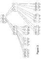
- FIG. 3 depicts a module tiling with inferior inter-module connectivity
- FIG. 4 illustrates parallel routing of inter-module signals according to certain embodiments of the invention.
- FIG. 5 depicts data and control links for an inter-node link or connection according to certain embodiments of the invention.
- Preferred embodiments of the invention provide massively parallel computer systems in which processor nodes are interconnected in a Kautz-like topology.
- the inter-node routing may be arranged so that a high percentage of the inter-node connections or links may remain on a module (i.e., intra-module) and avoid inter-module connections, thus reducing the amount of inter-node connections that must involve a backplane, cables, or the like.
- the inter-node connections that must be inter-module (and thus require a backplane or cables, or the like) may be arranged in a parallel fashion.
- Certain embodiments of the invention use a Kautz topology for data links and data flow to interconnect the node, but they are not purely directed graphs because they include a control link back channel link from receiver to sender. This link is used for flow control and status, among other things.
- Kautz interconnection topologies are unidirectional, directed graphs (digraphs).
- Kautz digraphs are characterized by a degree k and a diameter n.
- the degree of the digraph is the maximum number of arcs (or links or edges) input to or output from any node.
- the diameter is the maximum number of arcs that must be traversed from any node to any other node in the topology.
- the order O of a graph is the number of nodes it contains.
- the order of a Kautz digraph is (k+1)k n ⁇ 1 .
- the diameter of a Kautz digraph increases logarithmically with the order of the graph.
- FIG. 1A depicts a very simple Kautz topology for descriptive convenience.
- the system 100 has degree three; that is, each node has three ingress links 110 and three egress links 112 .
- the topology has diameter one, meaning that any node can communicate with any other node in a maximum of one hop.
- the topology is order 4 , meaning that there are 4 nodes.
- FIG. 1B shows a system that is order 12 and diameter two. By inspection, one can verify that any node can communicate with any other node in a maximum of two hops.
- FIG. 1C shows a system that is degree three and diameter three, having order 36 . One quickly sees that the complexity of the system grows quickly. It would be counter-productive to depict and describe preferred systems such as those having hundreds of nodes or more.
- the table below shows how the order O of a system changes as the diameter n grows for a system of fixed degree k.
- any (x,y) pair satisfying (1) specifies a direct egress link from node x.
- node 1 has egress links to the set of nodes 30 , 31 and 32 . Iterating through this procedure for all nodes in the system will yield the interconnections, links, arcs or edges needed to satisfy the Kautz topology. (As stated above, communication between two arbitrarily selected nodes may require multiple hops through the topology but the number of hops is bounded by the diameter of the topology.)
- the system is arranged into multiple modules.
- the modules are created to have a particular size (i.e., number of nodes on the module) and a particular set of nodes on the module. It has been observed by the inventors that careful selection of the module size and careful attention to the selection of the set of nodes to include on a given module can significantly reduce wiring problems in systems built with the Kautz topology.
- the Kautz topology is uniformly tiled.
- the Kautz graph is one-to-one mapped to satisfy the following equation.
- t V G ⁇ I ⁇ V T (2)
- V G is the set of vertices of a Kautz graph
- V T is the set of vertices of a tile (i.e., a smaller graph, implemented as a module of nodes)
- I is an index set.
- (x,y) is an edge within tile T then (t ⁇ 1 (i,x), t ⁇ 1 (i,y) is an edge of Kautz graph G.
- the tiles or modules are arranged to maximize the number of edges of the tile T. That is, the tiles or modules are arranged so that a maximum number of edges, arc, or links in the Kautz topology are contained on the tiles. All the remaining edges by necessity are inter-tile (or inter-module). By doing this, node interconnections will be maximized to remain intra-module.
- a de Bruijn graph is closely related to a Kautz graph.
- a de Bruijn graph has vertices that may be labeled by strings of n integers base k, as follows: c 1 c 2 . . . c n ⁇ Z k n (4)
- edges, links or arcs in a Kautz graph may be expressed as follows: (s 0 c 1 c 2 . . . c n ⁇ 1 , [s 0 +c 1 +1]c 2 c 3 . . . c n ) (6) where [s 0 +c 1 +1] is taken modulo k+1.
- the tile M must be equivalent to a subgraph of a de Bruijn graph of diameter m and degree k containing all the nodes of the de Bruijn graph but only a subset of the edges subject to the condition that the edges on the tile cannot form any directed loops.
- the subgraph with the maximal number of intra-module edges (without directed loops) should be chosen subject to the condition that the tile can be extended to form a complete tiling of the system.
- This map may in particular be chosen to satisfy the following conditions: ⁇ (P(u)) P( ⁇ (u)), ⁇ u ⁇ G ⁇ (C(u)) ⁇ C( ⁇ (u)), ⁇ u ⁇ G where C(u) denotes the set of nodes which are reached from edges beginning at node u and P(u) denotes the set of nodes from which node u can be reached by following a single edge.
- each module has k m nodes, and each node on the module can be assigned a label d 1 . . . d m ⁇ Z k m such that inter-node connections that are intra-module correspond to a subset of the edges (d 1 . . . d m , d 2 . . . d m+1 ) of a de Bruijn graph of diameter m and degree k, subject to the condition that there are no directed closed loops formed from the inter-node connections on a module.
- f(x,y) equals x+y mod k, or f(x,y) equals x ⁇ y mod k.
- T contains the edge (x o , x 1 ).
- edge x o , x 1
- this vertex to be t ⁇ 1 (i, x 1 ).
- map t ⁇ 1 is defined for the new value of x. In this fashion the complete tiling may be completed.
- FIG. 1D for example shows a module or tile for a very simple Kautz topology of order 36 and degree three. Each module has nine nodes, as depicted.
- the table shows how the nodes and modules connect. Notice how the linear labels are distributed among modules. For example, linearly labeled nodes 0 - 9 are not all assigned to module 0 .
- the interconnection among nodes is defined by equation 1, and the assignment among modules is a result of the tiling method employed.
- FIG. 1D is particularly simple in comparison to the larger systems of preferred embodiments. The size of preferred embodiments is prohibitively large to depict by figures or tables and instead is explained by the mathematics above. This example is utilized to illustrate the complexity of module assignment and the interconnections among nodes.
- module size is an integral power of the degree (k). Certain embodiments maximize this size as described above, i.e., largest subgraph without directed loops, but others may be smaller for practical considerations in building modules. These are substantially optimal in terms of maximizing edges to be intra-module.
- Certain embodiments use a module size of 27 nodes where each node is of degree 3.
- Each module has a particular set of nodes thereon (as described above) and may be used to build Kautz topologies of 108, 324, 972 or more nodes, or de Bruijn topologies with multiples of 27 nodes.
- FIG. 2 depicts a module arrangement having 27 nodes, numbered 0 through 26 in the upper right corner of nodes.
- These node numbers are, in certain embodiments, the numbering schema of equations 7 and 8. That is, the node numbers shown are adjacent in the number space provided by the discrete differential numbering scheme outlined above, though they need not be adjacent in the numbering of nodes of the Kautz topology as expressed in equation 1.
- the node identifier is expressed in the upper right corner of the node in decimal form, and in the middle of the node it is expressed in ternary form.
- each node identifies the egress links 202 and ingress links 204 . Focusing on egress links for the time being (with the explanation extending to ingress links too), node 7 has egress links going to nodes 21 , 22 , and 23 (upper right notation, i.e., node identifier) on other modules in the system.
- the figure depicts just the numbering scheme and not the node identification within the Kautz topology.
- the actual interconnectivity is defined by equation 1.
- some connections depicted on FIG. 2 identify node numbers (via its number identifier), which are the same, even though in the larger system the node numbers will go to different nodes.
- the figure shows nodes 17 , 26 and 8 , each with output links to another node (off module) identified by number 26 .
- the node 26 driven by nodes 17 and 26 (upper right of FIG. 2 ) is on a different module than the node 26 driven by node 8 .
- the actual nodes involved are governed by the above equations.
- FIG. 4 depicts a simplified diagram, drawn in perspective, to illustrate the parallel routing that results from the tiling approach discussed above.
- a first module 402 has an output pin 404 in communication with backplane trace 408 on backplane 406 .
- backplane trace 408 is parallel and horizontal to pin 410 on module 412 . That is, the backplane trace has no vertical runs. Under preferred embodiments of the invention, every backplane run will be parallel in a similar manner. Though many layers may be needed for the backplane when there are a significant number of modules, the backplane traces will not need vertical runs to connect the relevant pins and links, and instead runs will be horizontal and parallel.
- the trace 408 may correspond to the connection from the node with discrete differential number 5 (lower part of figure) to another node on a different module ( 412 ) with discrete differential identifier 17 . Notice in the upper right of FIG. 2 that every node 17 receives an input from another node 5 (discrete differential number).
- each module will have 39 pins (e.g., 404 and 410 ), and every backplane trace will run horizontal and parallel to other traces. Only one backplane layer 406 is shown in FIG. 4 for clarity, but a system of 972 nodes may require about 20 such layers. Such a backplane, however, will be faster and have better signal integrity than one that did not have parallel routes and which needed vertical runs, vias and the likes to provide connectivity among modules.
- Each node on the system may communicate with any other node on the system by appropriately routing messages onto the communication fabric via an egress link 202 .
- Some of these egress links will be inter-module, such as the ones depicted in connection with node 7 .
- Others will be intra-module, such as those being depicted in connection with node 2 which go to nodes 6 , 7 , and 8 on the same module.
- Some nodes have some links intra-module and some inter-module, see for example node 12 .
- any data message on the fabric includes routing information in the header of the message (among other information).
- the routing information specifies the entire route of the message.
- the routing information is a bit string of 2-bit routing codes, each routing code specifying whether a message should be received locally (i.e., this is the target node of the message) or identifying one of three egress links.
- each node has tables programmed with the routing information. For a given node x to communicate with another node z, node x accesses the table and receives a bit string for the routing information.
- this bit string is used to control various switches along the message's route to node z, in effect specifying which link to utilize at each node during the route.
- Another node j may have a different bit string when it needs to communicate with node z, because it will employ a different route to node z and the message may utilize different links at the various nodes in its route to node z.
- the routing information is not literally an “address” (i.e., it doesn't uniquely identify node z) but instead is a set of codes to control switches for the message's route.
- the routes are determined a priori based on the interconnectivity of the Kautz topology as expressed in equation 1. That is, the Kautz topology is defined, and the various egress links for each node are assigned a code (i.e., each link being one of three egress links). Thus, the exact routes for a message from node x to node z are known in advance, and the egress link selections may be determined in advance as well. These link selections are programmed as the routing information. These tables may be reprogrammed as needed, for example, to route around faulty links or nodes.
- Certain embodiments modify the routing information in the message header en route for easier processing. For example, a node will analyze a 2 bit field of the routing information to determine which link the message should use, e.g., one of three egress links or it should be kept local (i.e., this is the destination node). This could be the least significant numeral, digits or bits of the routing field, but it need not be limited to such (i.e., it depends on the embodiment).
- the node shifts the routing bit string accordingly (e.g., by 2 bits) so the next node in the route can perform an exactly similar set of operation: i.e., process the lowest two bits of the route code to determine if the message should be handled locally or forwarded on a specific one of three egress links).
- the routing information is used to identify portions in a cross point buffer to hold the data so that the message may be stored until it may be forwarded on the appropriate link. (Certain embodiments support cut-through routing to avoid the buffer if the appropriate link is not busy when the message arrive or becomes free during reception of the message.)
- the messages also contain other information such as virtual channel identification information.
- virtual channel information is used so that each link may be associated with multiple virtual channels and so that deadlock avoidance techniques may be implemented.
- FIG. 3 shows an arrangement also involving 27 nodes per module.
- the arrangement seems well-organized (e.g., tree like) only about 30% of the inter-node connections remains on module, meaning more of the inter-node connections will require a backplane or the like, inhibiting the ability to build larger systems.
- the computing system is not configured as a Kautz digraph in pure form in that the communication is not purely unidirectional. Instead, certain preferred embodiments have data communication implemented on unidirectional directed links (or circuits) and use a back channel control link (or circuit) for flow control and maintenance purposes.
- FIG. 5 for example shows two nodes, sender 502 and receiver 504 , following the unidirectional convention used above in discussing Kautz topologies. These nodes could correspond, for example, to two intra-module nodes such as nodes 18 and 2 in FIG. 2 .
- the link 506 connecting the two nodes includes unidirectional data lanes 508 and unidirectional control lanes 510 .
- the direction of the data lanes 508 is consistent with the convention used above in discussing the unidirectional flow of the Kautz digraph.
- the direction of the control link is in the opposite direction, i.e., from data receiving node 504 to data transmitting node 502 .
- the arrangement is asymmetric in the sense that there are more forward data lane circuits than there are reverse control lane circuits. In certain embodiments there are eight data circuits and one control circuit between two connected nodes.
- each sender 502 assigns a link sequence number (LSN) to every outgoing packet.
- LSN link sequence number
- the sender 502 also keeps transmitted packets in a replay buffer until it has been confirmed (more below) that the packets have been successfully received.
- Receiver nodes receive packets and keep track of the LSN of the most recently received error free packet as part of its buffer status. Periodically, the receiver node 504 transmits buffer status back to the sender using the control circuit 510 . In certain embodiments, this status is transmitted as frequently as possible.
- the LSN corresponds to the most recently received packet if there has been no error. If there has been an error detected, the buffer status will indicate error and include the LSN of the last packet correctly received.
- the sending node 502 identifies the LSN in the buffer status packet and from this realizes that all packets up to and including the identified LSN have been received at the receiving node 504 in acceptable condition.
- the sender 502 may then delete packets from the replay buffer with LSNs up to and including the LSN received in the status packet. If an error has been detected, the sender will resend all packets in the replay buffer starting after the LSN of the buffer status (the receiving node will have dropped such in anticipation of the replay and to ensure that all packets from the same source, going to the same destination, along the same route, with the same virtual channel are delivered and kept in order).
- packet error detection and recovery is performed at the link level. Likewise packets are guaranteed to be delivered in order at the link-level.
- the control circuits are also used to convey buffer status information for downstream nodes to indicate whether buffer space associated with virtual channels are free or busy.
- the nodes use a cross point buffer to store data from the links and to organize and control the data flow as virtual channel assignments over the links to avoid deadlock.
- a debit/credit mechanism is used in which the receiving node 504 informs the sending node 502 of how much space is available in the buffers (not shown) of the receiving node 504 for each virtual channel and port.
- a sender 502 will not send information unless it knows that there is buffer space for the virtual channel in the next downstream node along the route.
- the control packet stream carries a current snapshot of the cross point buffer entry utilization for each of the crosspoint buffers it has (which depends on the degree of the system).
- the control link may also be used for out-of-band communication between connected nodes by using otherwise unused fields in the packet to communicate. This mechanism may be used for miscellaneous purposes.
- no single or (if degree three or higher) double failure can isolate any working node or subset of nodes from the rest of the network.
- No single link or node failure increases the network diameter by more than one hop.
- Certain embodiments of the invention use multiple paths in the topology to avoid congestion and faulty links or nodes.
- Certain embodiments used discrete differential in the low order positions of the label identification. This is particularly helpful for parallel routing.
- Certain embodiments of the invention allow what are above described as a tile to be combined on to module.
- two tiles may be formed on a module, and a module under these arrangement will have pk m nodes where p is an integer.
- Appendix A is a listing of a particular 972 node, 36 module, degree three system.
- the columns identify the Kautz number (0-971), the node identification (per module) and specify the other nodes to which each node connects. From this, one can determine node-to-node interconnectivity for each node in the system.
Abstract
Description
-
- U.S. patent application Ser. No. 11/335,421, filed Jan. 19, 2006, entitled SYSTEM AND METHOD OF MULTI-CORE CACHE COHERENCY;
- U.S. patent application Ser. No. 11/594,426, filed on an even date herewith, entitled SYSTEM AND METHOD FOR PREVENTING DEADLOCK IN RICHLY-CONNECTED MULTI-PROCESSOR COMPUTER SYSTEM USING DYNAMIC ASSIGNMENT OF VIRTUAL CHANNELS;
- U.S. patent application Ser. No. 11/594,421, filed on an even date herewith, entitled LARGE SCALE MULTI-PROCESSOR SYSTEM WITH A LINK-LEVEL INTERCONNECT PROVIDING IN-ORDER PACKET DELIVERY;
- U.S. patent application Ser. No. 11/594,442, filed on an even date herewith, entitled MESOCHRONOUS CLOCK SYSTEM AND METHOD TO MINIMIZE LATENCY AND BUFFER REQUIREMENTS FOR DATA TRANSFER IN A LARGE MULTI-PROCESSOR COMPUTING SYSTEM;
- U.S. patent application Ser. No. 11/594,427, filed on an even date herewith, entitled REMOTE DMA SYSTEMS AND METHODS FOR SUPPORTING SYNCHRONIZATION OF DISTRIBUTED PROCESSES IN A MULTIPROCESSOR SYSTEM USING COLLECTIVE OPERATIONS;
- U.S. patent application Ser. No. 11/594/423, filed on an even date herewith, entitled COMPUTER SYSTEM AND METHOD USING A KAUTZ-LIKE DIGRAPH TO INTERCONNECT COMPUTER NODES AND HAVING CONTROL BACK CHANNEL BETWEEN NODES;
- U.S. patent application Ser. No. 11/594,420, filed on an even date herewith, entitled SYSTEM AND METHOD FOR ARBITRATION FOR VIRTUAL CHANNELS TO PREVENT LIVELOCK IN A RICHLY-CONNECTED MULTI-PROCESSOR COMPUTER SYSTEM;
- U.S. patent application Ser. No. 11/594,441, filed on an even date herewith, entitled LARGE SCALE COMPUTING SYSTEM WITH MULTI-LANE MESOCHRONOUS DATA TRANSFERS AMONG COMPUTER NODES;
- U.S. patent application Ser. No. 11/594,405, filed on an even date herewith, entitled SYSTEM AND METHOD FOR COMMUNICATING ON A RICHLY CONNECTED MULTI-PROCESSOR COMPUTER SYSTEM USING A POOL OF BUFFERS FOR DYNAMIC ASSOCIATION WITH A VIRTUAL CHANNEL;
- U.S. patent application Ser. No. 11/594,443, filed on an even date herewith, entitled RDMA SYSTEMS AND METHODS FOR SENDING COMMANDS FROM A SOURCE NODE TO A TARGET NODE FOR LOCAL EXECUTION OF COMMANDS AT THE TARGET NODE;
- U.S. patent application Ser. No. 11/594,447, filed on an even date herewith, entitled SYSTEMS AND METHODS FOR REMOTE DIRECT MEMORY ACCESS TO PROCESSOR CACHES FOR RDMA READS AND WRITES; and
- U.S. patent application Ser. No. 11/594,446, filed on an even date herewith, entitled SYSTEM AND METHOD FOR REMOTE DIRECT MEMORY ACCESS WITHOUT PAGE LOCKING BY THE OPERATING SYSTEM.
d i =f(c i+n−m ,c i)
wherein f(x,y) is a function which for fixed X acts a permutation on Zk through y→f (X,y) and which for fixed Y acts as a permutation on Zk through x→f (x,Y) and where ci's encode the Kautz coordinates si through
c i =s i −s i−1−1 mod(k+1)
| Order | ||
| Diameter (n) | k = 2 | k = 3 | k = 4 | ||
| 3 | 12 | 36 | 80 | ||
| 4 | 24 | 108 | 320 | ||
| 5 | 48 | 324 | 1280 | ||
| 6 | 96 | 972 | 5120 | ||
y=(−x*k−j)mod O, where 1≦j≦k (1)
Thus, any (x,y) pair satisfying (1) specifies a direct egress link from node x. For example, with reference to
t:VG→I×VT (2)
In the above, VG is the set of vertices of a Kautz graph; VT is the set of vertices of a tile (i.e., a smaller graph, implemented as a module of nodes); and I is an index set. Moreover, if (x,y) is an edge within tile T then (t−1(i,x), t−1(i,y) is an edge of Kautz graph G.
s1s2 . . . snεZk+1 n, si≠si+1 (3)
c1c2 . . . cnεZk n (4)
T:s 1 . . . s n →c 1 . . . c n−1 , c i=(s i+1 −s i)(mod k+1)−1 (5)
(s0c1c2 . . . cn−1, [s0+c1+1]c2c3 . . . cn) (6)
where [s0+c1+1] is taken modulo k+1.
Π(P(u)) P(Π(u)), ∀uεG
Π(C(u))−C(Π(u)), ∀uεG
where C(u) denotes the set of nodes which are reached from edges beginning at node u and P(u) denotes the set of nodes from which node u can be reached by following a single edge.
d i =f(c i+n−m ,c i) (7)
wherein f(x,y) is a function which for fixed X acts a permutation on Zk through y→f(X,y) and which for fixed Y acts as a permutation on Zk through x→f (x,Y) and where ci's encode the Kautz coordinates si through
c i =s i −s i−1−1 mod(k+1) (8)
| Shift | ||||
| Register | map | |||
| Linear | Exits | label | to deBruijn | Assignment |
| label | 0 | 1 | 2 | s0 | s1 | s2 | s0 | c1 | c2 | mod | node |
| 0 | 35 | 34 | 33 | 0 | 3 | 0 | 0 | 2 | 0 | 0 | 6 |
| 1 | 32 | 31 | 30 | 0 | 3 | 1 | 0 | 2 | 1 | 0 | 7 |
| 2 | 29 | 28 | 27 | 0 | 3 | 2 | 0 | 2 | 2 | 3 | 8 |
| 3 | 26 | 25 | 24 | 0 | 2 | 3 | 0 | 1 | 0 | 3 | 3 |
| 4 | 23 | 22 | 21 | 0 | 2 | 0 | 0 | 1 | 1 | 1 | 4 |
| 5 | 20 | 19 | 18 | 0 | 2 | 1 | 0 | 1 | 2 | 2 | 5 |
| 6 | 17 | 16 | 15 | 0 | 1 | 2 | 0 | 0 | 0 | 1 | 0 |
| 7 | 14 | 13 | 12 | 0 | 1 | 3 | 0 | 0 | 1 | 1 | 1 |
| 8 | 11 | 10 | 9 | 0 | 1 | 0 | 0 | 0 | 2 | 1 | 2 |
| 9 | 8 | 7 | 6 | 1 | 0 | 1 | 1 | 2 | 0 | 1 | 6 |
| 10 | 5 | 4 | 3 | 1 | 0 | 2 | 1 | 2 | 1 | 1 | 7 |
| 11 | 2 | 1 | 0 | 1 | 0 | 3 | 1 | 2 | 2 | 0 | 8 |
| 12 | 35 | 34 | 33 | 1 | 3 | 0 | 1 | 1 | 0 | 0 | 3 |
| 13 | 32 | 31 | 30 | 1 | 3 | 1 | 1 | 1 | 1 | 2 | 4 |
| 14 | 29 | 28 | 27 | 1 | 3 | 2 | 1 | 1 | 2 | 3 | 5 |
| 15 | 26 | 25 | 24 | 1 | 2 | 3 | 1 | 0 | 0 | 2 | 0 |
| 16 | 23 | 22 | 21 | 1 | 2 | 0 | 1 | 0 | 1 | 2 | 1 |
| 17 | 20 | 19 | 18 | 1 | 2 | 1 | 1 | 0 | 2 | 2 | 2 |
| 18 | 17 | 16 | 15 | 2 | 1 | 2 | 2 | 2 | 0 | 2 | 6 |
| 19 | 14 | 13 | 12 | 2 | 1 | 3 | 2 | 2 | 1 | 2 | 7 |
| 20 | 11 | 10 | 9 | 2 | 1 | 0 | 2 | 2 | 2 | 1 | 8 |
| 21 | 8 | 7 | 6 | 2 | 0 | 1 | 2 | 1 | 0 | 1 | 3 |
| 22 | 5 | 4 | 3 | 2 | 0 | 2 | 2 | 1 | 1 | 3 | 4 |
| 23 | 2 | 1 | 0 | 2 | 0 | 3 | 2 | 1 | 2 | 0 | 5 |
| 24 | 35 | 34 | 33 | 2 | 3 | 0 | 2 | 0 | 0 | 3 | 0 |
| 25 | 32 | 31 | 30 | 2 | 3 | 1 | 2 | 0 | 1 | 3 | 1 |
| 26 | 29 | 28 | 27 | 2 | 3 | 2 | 2 | 0 | 2 | 3 | 2 |
| 27 | 26 | 25 | 24 | 3 | 2 | 3 | 3 | 2 | 0 | 3 | 6 |
| 28 | 23 | 22 | 21 | 3 | 2 | 0 | 3 | 2 | 1 | 3 | 7 |
| 29 | 20 | 19 | 18 | 3 | 2 | 1 | 3 | 2 | 2 | 2 | 8 |
| 30 | 17 | 16 | 15 | 3 | 1 | 2 | 3 | 1 | 0 | 2 | 3 |
| 31 | 14 | 13 | 12 | 3 | 1 | 3 | 3 | 1 | 1 | 0 | 4 |
| 32 | 11 | 10 | 9 | 3 | 1 | 0 | 3 | 1 | 2 | 1 | 5 |
| 33 | 8 | 7 | 6 | 3 | 0 | 1 | 3 | 0 | 0 | 0 | 0 |
| 34 | 5 | 4 | 3 | 3 | 0 | 2 | 3 | 0 | 1 | 0 | 1 |
| 35 | 2 | 1 | 0 | 3 | 0 | 3 | 3 | 0 | 2 | 0 | 2 |
Claims (11)
d i =f(c i +n−m,c i)
Priority Applications (2)
| Application Number | Priority Date | Filing Date | Title |
|---|---|---|---|
| US11/594,416 US7660270B2 (en) | 2006-11-08 | 2006-11-08 | Computer system and method using efficient module and backplane tiling to interconnect computer nodes via a Kautz-like digraph |
| PCT/US2007/082851 WO2008057828A2 (en) | 2006-11-08 | 2007-10-29 | Computer system and method using efficient module and backplane tiling |
Applications Claiming Priority (1)
| Application Number | Priority Date | Filing Date | Title |
|---|---|---|---|
| US11/594,416 US7660270B2 (en) | 2006-11-08 | 2006-11-08 | Computer system and method using efficient module and backplane tiling to interconnect computer nodes via a Kautz-like digraph |
Publications (2)
| Publication Number | Publication Date |
|---|---|
| US20080126571A1 US20080126571A1 (en) | 2008-05-29 |
| US7660270B2 true US7660270B2 (en) | 2010-02-09 |
Family
ID=39465065
Family Applications (1)
| Application Number | Title | Priority Date | Filing Date |
|---|---|---|---|
| US11/594,416 Expired - Fee Related US7660270B2 (en) | 2006-11-08 | 2006-11-08 | Computer system and method using efficient module and backplane tiling to interconnect computer nodes via a Kautz-like digraph |
Country Status (1)
| Country | Link |
|---|---|
| US (1) | US7660270B2 (en) |
Families Citing this family (6)
| Publication number | Priority date | Publication date | Assignee | Title |
|---|---|---|---|---|
| US8255599B2 (en) * | 2006-03-28 | 2012-08-28 | Integrated Device Technology Inc. | Packets transfer device having data absorbing buffers with elastic buffer capacities |
| US7852867B2 (en) | 2007-07-06 | 2010-12-14 | Integrated Deoice Technology, Inc. | Integrated memory for storing egressing packet data, replay data and to-be egressed data |
| US7773591B2 (en) | 2007-07-06 | 2010-08-10 | Integrated Device Technology, Inc. | Integrated memory for storing egressing packet data, replay data and to-be egressed data |
| US7792014B2 (en) * | 2007-09-28 | 2010-09-07 | Integrated Device Technology, Inc. | Method of skipping nullified packets during mass replay from replay buffer |
| US8065433B2 (en) | 2009-01-09 | 2011-11-22 | Microsoft Corporation | Hybrid butterfly cube architecture for modular data centers |
| WO2018073674A1 (en) * | 2016-10-21 | 2018-04-26 | Levi Dinor Adam Vestergaard | Flat data routing chain |
Citations (4)
| Publication number | Priority date | Publication date | Assignee | Title |
|---|---|---|---|---|
| US5134690A (en) | 1989-06-26 | 1992-07-28 | Samatham Maheswara R | Augumented multiprocessor networks |
| US5513371A (en) | 1992-01-07 | 1996-04-30 | International Business Machines Corporation | Hierarchical interconnection network architecture for parallel processing, having interconnections between bit-addressible nodes based on address bit permutations |
| US6721311B1 (en) * | 1999-08-10 | 2004-04-13 | Colorado Seminary | Self-routing permutation networks based on de Bruijn digraphs |
| US20060056308A1 (en) | 2004-05-28 | 2006-03-16 | International Business Machines Corporation | Method of switching fabric for counteracting a saturation tree occurring in a network with nodes |
-
2006
- 2006-11-08 US US11/594,416 patent/US7660270B2/en not_active Expired - Fee Related
Patent Citations (4)
| Publication number | Priority date | Publication date | Assignee | Title |
|---|---|---|---|---|
| US5134690A (en) | 1989-06-26 | 1992-07-28 | Samatham Maheswara R | Augumented multiprocessor networks |
| US5513371A (en) | 1992-01-07 | 1996-04-30 | International Business Machines Corporation | Hierarchical interconnection network architecture for parallel processing, having interconnections between bit-addressible nodes based on address bit permutations |
| US6721311B1 (en) * | 1999-08-10 | 2004-04-13 | Colorado Seminary | Self-routing permutation networks based on de Bruijn digraphs |
| US20060056308A1 (en) | 2004-05-28 | 2006-03-16 | International Business Machines Corporation | Method of switching fabric for counteracting a saturation tree occurring in a network with nodes |
Non-Patent Citations (6)
| Title |
|---|
| International Search Report for PCT/US07/82851 mailed Mar. 26, 2008. |
| Liu, Guoping and Lee, Y. "Optimal Routing Algorithsm for Generalized de Bruijn Digraphs". Parallel Processing, 1993. ICPP 1993. International Conference on Parallel Processing. vol. 3, Aug. 16-20, 1993, pp. 167-174. * |
| Panchapakesan, G. and Sengupta, A. "On Multihop Optical Network Topology using Kautz Digraphs". IEEE Xplore. University of South Carolina. Copyright 1995 IEEE. * |
| Samatham, M. and Pradhan, D. "The De Bruijn Multiprocessor Netowrk: A Versatile Parallel Processing and Sorting Network for VLSI". IEEE Transactions on Computers, vol. 38, No. 4, Apr. 1989. * |
| Samatham, M. and Pradhan, D. "The De Bruijn Multiprocessor Network: A versatile Parallel Processing and Sorting Network for VLSI". IEEE Transactions on Computers, vol. 38, No. 4, Apr. 1989. * |
| Smit, "An Algorithm for Generating Node Disjoint Routes in Kautz Diagraphs," IEEE, 1991, pp. 102-107. |
Also Published As
| Publication number | Publication date |
|---|---|
| US20080126571A1 (en) | 2008-05-29 |
Similar Documents
| Publication | Publication Date | Title |
|---|---|---|
| US9674116B2 (en) | Data distribution packet-flow interconnect fabric modular management optimized system | |
| US8184626B2 (en) | High-radix interprocessor communications system and method | |
| AU2018200158B2 (en) | Method And Apparatus To Manage The Direct Interconnect Switch Wiring And Growth In Computer Networks | |
| US8819611B2 (en) | Asymmetric mesh NoC topologies | |
| US20170118139A1 (en) | Fabric interconnection for memory banks based on network-on-chip methodology | |
| US4797882A (en) | Mesh-based switching network | |
| EP0821816B1 (en) | Adaptive routing mechanism for torus interconnection network | |
| US7660270B2 (en) | Computer system and method using efficient module and backplane tiling to interconnect computer nodes via a Kautz-like digraph | |
| US9825844B2 (en) | Network topology of hierarchical ring with recursive shortcuts | |
| CN107959643B (en) | Switching system constructed by switching chip and routing algorithm thereof | |
| Daneshtalab et al. | Low-distance path-based multicast routing algorithm for network-on-chips | |
| US7751344B2 (en) | Computer system and method using a kautz-like digraph to interconnect computer nodes and having control back channel between nodes | |
| JP2007532052A (en) | Scalable network for management of computing and data storage | |
| CN113204423A (en) | Method, system and readable medium for synchronizing computing task data | |
| JPH06266684A (en) | Interprocessor routing system | |
| WO2008057828A2 (en) | Computer system and method using efficient module and backplane tiling | |
| US7561584B1 (en) | Implementation of a graph property in a switching fabric for fast networking | |
| Rahman et al. | Dynamic communication performance of a TESH network under the nonuniform traffic patterns | |
| CN113268338A (en) | Communication implementation method and system of computing equipment | |
| Sauer et al. | Photonic interconnects for gigabit multicomputer communications | |
| Jahanshahi et al. | Interconnection Networks | |
| Yang et al. | Adaptive wormhole routing in k-ary n-cubes | |
| Nguyen | Cable-Geometric and Moderate Error-Proof Approach for Low-Latency Interconnection Networks. | |
| CN116349208A (en) | Routing method and data forwarding system | |
| Yu et al. | RingCube—An incrementally scale-out optical interconnect for cloud computing data center |
Legal Events
| Date | Code | Title | Description |
|---|---|---|---|
| AS | Assignment |
Owner name: SICORTEX, INC., MASSACHUSETTS Free format text: ASSIGNMENT OF ASSIGNORS INTEREST;ASSIGNORS:LEONARD, JUDSON S.;REILLY, MATTHEW H.;STEWART, LAWRENCE C.;AND OTHERS;REEL/FRAME:018790/0472 Effective date: 20070111 Owner name: SICORTEX, INC.,MASSACHUSETTS Free format text: ASSIGNMENT OF ASSIGNORS INTEREST;ASSIGNORS:LEONARD, JUDSON S.;REILLY, MATTHEW H.;STEWART, LAWRENCE C.;AND OTHERS;REEL/FRAME:018790/0472 Effective date: 20070111 |
|
| AS | Assignment |
Owner name: HERCULES TECHNOLOGY I, LLC, CALIFORNIA Free format text: ASSIGNMENT OF ASSIGNORS INTEREST;ASSIGNOR:HERCULES TECHNOLOGY, II L.P.;REEL/FRAME:023334/0418 Effective date: 20091006 Owner name: HERCULES TECHNOLOGY I, LLC,CALIFORNIA Free format text: ASSIGNMENT OF ASSIGNORS INTEREST;ASSIGNOR:HERCULES TECHNOLOGY, II L.P.;REEL/FRAME:023334/0418 Effective date: 20091006 |
|
| AS | Assignment |
Owner name: HERCULES TECHNOLOGY II, LLC,CALIFORNIA Free format text: ASSIGNMENT OF ASSIGNORS INTEREST;ASSIGNOR:HERCULES TECHNOLOGY I, LLC;REEL/FRAME:023719/0088 Effective date: 20091230 Owner name: HERCULES TECHNOLOGY II, LLC, CALIFORNIA Free format text: ASSIGNMENT OF ASSIGNORS INTEREST;ASSIGNOR:HERCULES TECHNOLOGY I, LLC;REEL/FRAME:023719/0088 Effective date: 20091230 |
|
| CC | Certificate of correction | ||
| REMI | Maintenance fee reminder mailed | ||
| LAPS | Lapse for failure to pay maintenance fees | ||
| STCH | Information on status: patent discontinuation |
Free format text: PATENT EXPIRED DUE TO NONPAYMENT OF MAINTENANCE FEES UNDER 37 CFR 1.362 |
|
| FP | Lapsed due to failure to pay maintenance fee |
Effective date: 20140209 |