US7654423B1 - Motor vehicle roof standoff - Google Patents
Motor vehicle roof standoff Download PDFInfo
- Publication number
- US7654423B1 US7654423B1 US10/968,648 US96864804A US7654423B1 US 7654423 B1 US7654423 B1 US 7654423B1 US 96864804 A US96864804 A US 96864804A US 7654423 B1 US7654423 B1 US 7654423B1
- Authority
- US
- United States
- Prior art keywords
- roof
- standoff
- motor vehicle
- standoffs
- inches
- Prior art date
- Legal status (The legal status is an assumption and is not a legal conclusion. Google has not performed a legal analysis and makes no representation as to the accuracy of the status listed.)
- Expired - Fee Related, expires
Links
- 230000001012 protector Effects 0.000 claims description 20
- 238000000034 method Methods 0.000 claims description 13
- 238000006748 scratching Methods 0.000 claims 3
- 230000002393 scratching effect Effects 0.000 claims 3
- 230000000284 resting effect Effects 0.000 claims 1
- 239000000463 material Substances 0.000 abstract description 3
- 230000001681 protective effect Effects 0.000 description 2
- 229920005830 Polyurethane Foam Polymers 0.000 description 1
- 230000027455 binding Effects 0.000 description 1
- 238000009739 binding Methods 0.000 description 1
- 239000004566 building material Substances 0.000 description 1
- 239000000446 fuel Substances 0.000 description 1
- 238000012986 modification Methods 0.000 description 1
- 230000004048 modification Effects 0.000 description 1
- 239000011496 polyurethane foam Substances 0.000 description 1
Images


Classifications
-
- B—PERFORMING OPERATIONS; TRANSPORTING
- B60—VEHICLES IN GENERAL
- B60R—VEHICLES, VEHICLE FITTINGS, OR VEHICLE PARTS, NOT OTHERWISE PROVIDED FOR
- B60R9/00—Supplementary fittings on vehicle exterior for carrying loads, e.g. luggage, sports gear or the like
- B60R9/04—Carriers associated with vehicle roof
- B60R9/058—Carriers associated with vehicle roof characterised by releasable attaching means between carrier and roof
-
- B—PERFORMING OPERATIONS; TRANSPORTING
- B60—VEHICLES IN GENERAL
- B60R—VEHICLES, VEHICLE FITTINGS, OR VEHICLE PARTS, NOT OTHERWISE PROVIDED FOR
- B60R9/00—Supplementary fittings on vehicle exterior for carrying loads, e.g. luggage, sports gear or the like
- B60R9/08—Supplementary fittings on vehicle exterior for carrying loads, e.g. luggage, sports gear or the like specially adapted for sports gear
- B60R9/12—Supplementary fittings on vehicle exterior for carrying loads, e.g. luggage, sports gear or the like specially adapted for sports gear for skis
Definitions
- the present invention relates to standoffs for supporting cargo on a motor vehicle roof, and in particular to a roof standoffs system including two elongated lateral roof standoffs.
- roof racks are either permanent, or are so difficult to install and remove, that they are effectively permanent.
- Known removable roof racks often require manipulation of cumbersome hooks and latches, and as a result, users inevitably either leave the racks in place on the automobile roof long after they are needed, or are reluctant to install the rack at all.
- a protective cover for truck roofs is described in U.S. Pat. No. 6,315,327 for “Protective Cover for Vehicle Surface.”
- the cover of the '327 patent is a thin sheet-like article which preferably wraps around the rear edge of a truck roof, thereby allowing cargo, for example a ladder extended diagonally from the truck bed and over the cab, to be supported by the truck roof without damaging the truck roof.
- the roof protector of the '327 patent relies at least partially on the roof edge to maintain position (and is thus limited in positioning), and does not provide adequate vertical stand-off to protect an arced roof if cargo is carried horizontally on the roof of a motor vehicle versus diagonally.
- a car door protector is described in U.S. Pat. No. 3,147,176 for “Magnetic Car Door Protector.”
- the protector of the '176 patent is shallow and held in place by a large number of magnets. While such a protector provides some protection for a car door, the shallow design is only suitable for longitudinal placement and does not provide a vertical standoff sufficient if spaced apart for use on a cars roof (i.e., will not carry cargo high enough to clear a convex car roof profile), and the large number of magnets in the device of the '176, while required for the intended use on a car door, make the device difficult to position on a car roof or remove from a car roof.
- a motor vehicle roof protection system including standoffs providing sufficient height to carry cargo above the roof, and not requiring so many magnets that the standoffs are difficult to position or remove.
- a motor vehicle roof protection system includes a pair of magnetically attachable elongated roof standoffs to carry cargo above a car (or any motor vehicle) roof.
- One elongated roof standoff may be positioned near a forward end of the car roof and another elongated roof standoff may be positioned near a rearward end of the car roof.
- Magnets are embodied within the elongated roof standoffs to resist movement on the roof surface, with a layer of material under the magnets to protect the roof finish.
- the elongated roof standoffs have sloped tops, and the roof standoffs are positioned with the slopes facing forward to produce a downward force on the roof standoffs, and thereby secure the roof standoffs with fewer magnets than otherwise required.
- the tops include a textured portion for contact with cargo.
- the cargo may be held against the elongated roof standoffs using straps, ropes, or any suitable fastener.
- a method for protecting a motor vehicle roof includes the steps of positioning two elongated roof standoffs on the motor vehicle roof, placing cargo on the roof standoffs, and securing the cargo to the motor vehicle roof.
- Each elongated roof standoff comprises a roof standoff body and at least two spaced apart magnets embedded in the body.
- the roof standoffs are laterally aligned and longitudinally spaced apart on the roof, and positioning the two roof standoffs with sloping top surface sloping towards the front of the car.
- a motor vehicle roof protector system including at least one elongated roof standoff comprising a roof standoff body, a forward sloping top of the roof standoff body, and at least two spaced apart magnets embedded in the roof standoff body.
- FIG. 1A is a side view of a motor vehicle carrying cargo on a roof protection system according to the present invention.
- FIG. 1B is a rear view of the motor vehicle carrying cargo on the roof protection system.
- FIG. 2A is a detailed front view of a roof standoff of the roof protection system.
- FIG. 2B is a detailed top view of the roof standoff of the roof protection system.
- FIG. 2C is a detailed end view of the roof standoff of the roof protection system.
- FIG. 2D is a cross-sectional view of the roof standoff taken along line 2 D- 2 D of FIG. 2A .
- FIG. 2E is a cross-sectional view of the roof standoff taken along line 2 E- 2 E of FIG. 2C .
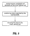
- FIG. 3 is a method for protecting a motor vehicle roof when carrying cargo thereon.
- FIG. 1A A side view of a motor vehicle 10 carry cargo 14 on roof standoffs 12 of a roof protection system is shown in FIG. 1A .
- the roof standoffs 12 (or lateral roof standoffs) rest on the roof 11 of the motor vehicle 10 .
- the roof standoffs 12 hold the cargo 14 high enough to clear a high point of an arced roof, or to allow protruding features (e.g., ski or snow board bindings) to clear the roof 11 .
- a strap 16 , cord, rope, or the like is used to secure the cargo 14 to the motor vehicle 10 , and the strap 16 is preferably independent of the roof standoffs 12 .
- the strap 16 might, for example, be looped though open windows, or hooked into edges of the roof or to window gutters.
- FIG. 1B A rear view of the motor vehicle 10 carrying cargo 14 on the roof standoffs 12 is shown in FIG. 1B .
- the roof standoffs 12 are laterally mounted on the roof 11 , and are longitudinally spaced apart, preferably far enough to provide stable support to the cargo 14 , and more preferably longitudinally spaced apart at least half the length of the roof 11 .
- One of the two roof standoff 12 generally resides near a forward edge 11 a of the roof 11
- another of the two roof standoff 12 generally resides near a rearward edge 11 b of the roof 11 .
- FIG. 2A A detailed front view of the roof standoff 12 of the roof protection system is shown in FIG. 2A , a detailed top view of the roof standoff 12 is shown in FIG. 2B , and a detailed end view of the roof standoff 12 is shown in FIG. 2C .
- the roof standoff 12 has roof standoff body 13 with an approximately vertical forward face 27 , an approximately vertical rear face 29 , a sloped top 26 and a concave base 22 .
- the roof standoff body 13 is preferably made from medium density polyurethane foam or a similar material.
- the sloped top 26 has a smaller height H 1 at a rounded forward edge 28 a , and a greater height H 2 at a rounded rearward edge 28 b .
- the height H 1 is preferable approximately 1.25 inches, and the height H 2 is preferably approximately two inches.
- the concave base 22 allows a better fit to typical motor vehicle roofs, and is preferably vertically recessed R approximately 0.38 inches at the center of the base 22
- the sloped top 26 is preferably positioned on the roof 11 with the slope forward, thereby providing some downward force on the roof standoff 12 from wind passing over the roof 11 . This additional downward force adds to the attraction of magnets 18 to the roof 11 , thereby allowing fewer magnets 18 to be embedded in the roof standoff 12 , thereby allowing easier positioning and removal of the roof standoff 12 .
- a textured area 20 resides on the rearward edge 28 b of the sloped top 26 and preferably covers an arced portion having a radius of approximately 0.5 inches.
- the textures area 20 is preferably embossed on the surface of the roof standoff body 13 , but may be a separate piece attached to the roof standoff body 13 .
- the sloping top 26 has a downward forward attitude as seen in FIG. 2C when the roof standoff base 22 is residing on the vehicle roof 11 .
- the sloping top 26 provides downward force on the roof standoff 12 when the motor vehicle 10 is moving forward due to air cooperating with the sloping top 26 .
- the roof standoff 12 is made to reside laterally on the roof 11 and is preferably slightly narrower than the roof 11 .
- the roof standoff 12 has a length Ls of preferably between 24 inches and 36 inches, and more preferably approximately 32 inches, a width Ws which is preferable between three and four inches, and more preferably approximately 3.5 inches, and a height Hs which is preferably between one and four inches, and more preferably approximately two inches.
- the roof standoff 12 thus preferably has a horizontal area between 72 and 144 square inches and more preferably has a horizontal area of approximately 112 square inches.
- FIG. 2D A cross-sectional view of the roof standoff 12 taken along line 2 D- 2 D of FIG. 2A is shown in FIG. 2D .
- At least two magnets 18 are embedding in the roof standoff 12 , and more preferably at least four magnets, and most preferably, four magnets.
- the magnets 18 are spaced apart, and preferably evenly spaced apart, more preferably spaced at least four inches apart, and most preferably spaced at least six inches apart.
- the magnets 18 preferably have a length Lm of between 1.5 and two inches, and more preferably approximately 17 ⁇ 8 inches, and a width Wm of between one and two inches, and more preferably approximately 1.5 inches.
- the magnets 18 thus have a preferred total horizontal area of between six and sixteen square inches and a more preferred horizontal area of approximately 111 ⁇ 4 square inches. Therefore, the preferred ratio of the horizontal area of the magnets 18 to the horizontal area of the roof standoff 12 is between 6/144 and 16/72 and more preferably the ratio of the horizontal areas is approximately 1/10.
- the limited attraction of the magnets combines with the aerodynamic downforce provided by the sloped top to retain the roof standoffs 12 on the vehicle roof.
- FIG. 2E A cross-sectional view of the roof standoff taken along line 2 E- 2 E of FIG. 2C is shown in FIG. 2E .
- the magnets 18 preferably have a thickness Tm of between 1 ⁇ 4 and 1 ⁇ 2 inches, and more preferably approximately 3 ⁇ 8 inches.
- the magnets 18 are preferably embedded a height Hm above the concave base 22 of the roof standoffs 12 , preferably approximately 1 ⁇ 4 inches.
- Other similar devices for example as described in U.S. Pat. No. 3,147,176 for “Magnetic Car Door Protector,” include a nearly continuous array of magnets which would make both adjustment and removal of the roof standoff difficult.
- FIG. 3 A method for protecting a motor vehicle roof when carrying cargo thereon is described in FIG. 3 .
- the method includes the steps of positioning two elongated roof standoffs on the motor vehicle roof, positioning cargo supported by the roof standoffs, and securing the cargo to the motor vehicle roof.
- the roof standoffs are preferably laterally aligned (i.e., run across the roof from one side to the opposite side) and longitudinally spaced apart on the roof, and with sloping top surface sloping towards the front of the car.
- the cargo may be secured with a strap, which strap is preferably independent of the roof standoffs and, for example, routed through open windows, or hooked to edges of the roof or window gutters.
Landscapes
- Engineering & Computer Science (AREA)
- Mechanical Engineering (AREA)
- Fittings On The Vehicle Exterior For Carrying Loads, And Devices For Holding Or Mounting Articles (AREA)
Abstract
Description
Claims (20)
Priority Applications (1)
| Application Number | Priority Date | Filing Date | Title |
|---|---|---|---|
| US10/968,648 US7654423B1 (en) | 2004-10-19 | 2004-10-19 | Motor vehicle roof standoff |
Applications Claiming Priority (1)
| Application Number | Priority Date | Filing Date | Title |
|---|---|---|---|
| US10/968,648 US7654423B1 (en) | 2004-10-19 | 2004-10-19 | Motor vehicle roof standoff |
Publications (1)
| Publication Number | Publication Date |
|---|---|
| US7654423B1 true US7654423B1 (en) | 2010-02-02 |
Family
ID=41581230
Family Applications (1)
| Application Number | Title | Priority Date | Filing Date |
|---|---|---|---|
| US10/968,648 Expired - Fee Related US7654423B1 (en) | 2004-10-19 | 2004-10-19 | Motor vehicle roof standoff |
Country Status (1)
| Country | Link |
|---|---|
| US (1) | US7654423B1 (en) |
Cited By (5)
| Publication number | Priority date | Publication date | Assignee | Title |
|---|---|---|---|---|
| US8517237B1 (en) * | 2010-02-11 | 2013-08-27 | Thomas Michael Barber | Vehicle roof rack pads |
| US9227491B1 (en) * | 2014-08-04 | 2016-01-05 | James K. Story, Jr. | Slidable cover for truck rack |
| US20170106732A1 (en) * | 2015-10-16 | 2017-04-20 | Robert Todd Tyack | Vehicular door suppression apparatus |
| US10286853B1 (en) | 2018-05-04 | 2019-05-14 | Frank Louis Carbone | Automated self-loading cargo carrier for vehicles |
| US20190283559A1 (en) * | 2018-03-15 | 2019-09-19 | Robert L. Mobley | Vehicle cab protective top cover system |
Citations (13)
| Publication number | Priority date | Publication date | Assignee | Title |
|---|---|---|---|---|
| US2844291A (en) * | 1956-05-14 | 1958-07-22 | Otis D Mcpheeters | Utility carriers |
| US3147176A (en) * | 1962-05-14 | 1964-09-01 | James E Haslam | Magnetic car door protector |
| US4294478A (en) | 1978-01-06 | 1981-10-13 | Marquette Russell C | Detachable protector for steel objects |
| US4690446A (en) | 1986-05-30 | 1987-09-01 | Dorfender Products Inc. | Bumper strip for automobiles |
| US4832396A (en) | 1985-01-16 | 1989-05-23 | Moreno Albert F | Magnetic strip for pick up camper shells etc. |
| US4940009A (en) | 1985-03-29 | 1990-07-10 | Keithley Jr Howard W | Shape adaptable protective cushion device and method of making and using same |
| US4957400A (en) * | 1989-04-13 | 1990-09-18 | Karp John D K | Pickup truck pads for carrying long loads |
| US5267763A (en) * | 1992-12-07 | 1993-12-07 | Klein Robert J | Vehicle side guard |
| US5529371A (en) | 1995-04-14 | 1996-06-25 | Egigian; Donald S. | Rail saver pad |
| EP0719676A1 (en) * | 1994-12-30 | 1996-07-03 | Diego Gemesio | Magnetic device to carry bicycles and/or skis on motor vehicle roofs |
| DE29719712U1 (en) * | 1997-11-06 | 1998-01-08 | Einert, Michael, 61267 Neu-Anspach | Vehicle roof attachment |
| US6315327B1 (en) * | 1999-02-26 | 2001-11-13 | Clay F. Woolsey | Protective cover for vehicle surface |
| US6692047B1 (en) | 2003-03-03 | 2004-02-17 | Interstate Recycling Corp. | Add-on automobile bumper and sidewall protective strips made from reclaimed tire treads |
-
2004
- 2004-10-19 US US10/968,648 patent/US7654423B1/en not_active Expired - Fee Related
Patent Citations (13)
| Publication number | Priority date | Publication date | Assignee | Title |
|---|---|---|---|---|
| US2844291A (en) * | 1956-05-14 | 1958-07-22 | Otis D Mcpheeters | Utility carriers |
| US3147176A (en) * | 1962-05-14 | 1964-09-01 | James E Haslam | Magnetic car door protector |
| US4294478A (en) | 1978-01-06 | 1981-10-13 | Marquette Russell C | Detachable protector for steel objects |
| US4832396A (en) | 1985-01-16 | 1989-05-23 | Moreno Albert F | Magnetic strip for pick up camper shells etc. |
| US4940009A (en) | 1985-03-29 | 1990-07-10 | Keithley Jr Howard W | Shape adaptable protective cushion device and method of making and using same |
| US4690446A (en) | 1986-05-30 | 1987-09-01 | Dorfender Products Inc. | Bumper strip for automobiles |
| US4957400A (en) * | 1989-04-13 | 1990-09-18 | Karp John D K | Pickup truck pads for carrying long loads |
| US5267763A (en) * | 1992-12-07 | 1993-12-07 | Klein Robert J | Vehicle side guard |
| EP0719676A1 (en) * | 1994-12-30 | 1996-07-03 | Diego Gemesio | Magnetic device to carry bicycles and/or skis on motor vehicle roofs |
| US5529371A (en) | 1995-04-14 | 1996-06-25 | Egigian; Donald S. | Rail saver pad |
| DE29719712U1 (en) * | 1997-11-06 | 1998-01-08 | Einert, Michael, 61267 Neu-Anspach | Vehicle roof attachment |
| US6315327B1 (en) * | 1999-02-26 | 2001-11-13 | Clay F. Woolsey | Protective cover for vehicle surface |
| US6692047B1 (en) | 2003-03-03 | 2004-02-17 | Interstate Recycling Corp. | Add-on automobile bumper and sidewall protective strips made from reclaimed tire treads |
Cited By (7)
| Publication number | Priority date | Publication date | Assignee | Title |
|---|---|---|---|---|
| US8517237B1 (en) * | 2010-02-11 | 2013-08-27 | Thomas Michael Barber | Vehicle roof rack pads |
| US9227491B1 (en) * | 2014-08-04 | 2016-01-05 | James K. Story, Jr. | Slidable cover for truck rack |
| US20170106732A1 (en) * | 2015-10-16 | 2017-04-20 | Robert Todd Tyack | Vehicular door suppression apparatus |
| US20190283559A1 (en) * | 2018-03-15 | 2019-09-19 | Robert L. Mobley | Vehicle cab protective top cover system |
| US10899209B2 (en) * | 2018-03-15 | 2021-01-26 | Robert L. Mobley | Vehicle cab protective top cover system |
| US10286853B1 (en) | 2018-05-04 | 2019-05-14 | Frank Louis Carbone | Automated self-loading cargo carrier for vehicles |
| US11661014B2 (en) | 2018-05-04 | 2023-05-30 | Frank Louis Carbone | Automated self-loading cargo carrier for vehicles |
Similar Documents
| Publication | Publication Date | Title |
|---|---|---|
| US5769291A (en) | Support pad assembly for carrying articles on vehicle roof | |
| US8777288B2 (en) | Folding roof rack for vehicle | |
| US8746469B1 (en) | Fishing rod caddy for pickup trucks | |
| US4295587A (en) | Article carrier for automotive vehicles | |
| US6799927B2 (en) | Tie down anchor system | |
| US4469257A (en) | Ski rack device for pickup trucks | |
| US9862258B2 (en) | Door protection device | |
| US5292045A (en) | Multipurpose rack for convertible top motor vehicles | |
| US6267427B1 (en) | Truck bed divider | |
| US5096106A (en) | Luggage carrier with pop-up frame | |
| US6196602B1 (en) | Deployable cargo rack for pickup truck | |
| US20180265007A1 (en) | Step Hitch Assembly | |
| US6019265A (en) | Snowboard rack for pickup trucks | |
| US7654423B1 (en) | Motor vehicle roof standoff | |
| US4747529A (en) | Collapsible ski rack | |
| US20060237501A1 (en) | Roof carrier for fishing rods | |
| US7004486B1 (en) | Running board storage box with gusset attachment | |
| US6454149B1 (en) | Device and method for transporting elongate objects using a pick-up truck | |
| US20090140561A1 (en) | Vehicle mounted printer station | |
| US5509764A (en) | Cargo securing system for pick-up trucks | |
| US7331623B1 (en) | Rack for supporting two canoes on pickup truck bed | |
| US7152769B2 (en) | Car top ski/snowboard carriers | |
| US7913885B2 (en) | Stowable apparatus for securing an extension ladder to a pickup truck | |
| WO2005033448A2 (en) | Method and apparatus for securing a sports board fin to a sports board | |
| US6678991B2 (en) | Fishing pole holder |
Legal Events
| Date | Code | Title | Description |
|---|---|---|---|
| AS | Assignment |
Owner name: BARSCO, LLC,CALIFORNIA Free format text: ASSIGNMENT OF ASSIGNORS INTEREST;ASSIGNOR:CHRISTIANSEN, WARREN;REEL/FRAME:019728/0082 Effective date: 20070807 |
|
| STCF | Information on status: patent grant |
Free format text: PATENTED CASE |
|
| FEPP | Fee payment procedure |
Free format text: PATENT HOLDER CLAIMS MICRO ENTITY STATUS, ENTITY STATUS SET TO MICRO (ORIGINAL EVENT CODE: STOM); ENTITY STATUS OF PATENT OWNER: MICROENTITY |
|
| FPAY | Fee payment |
Year of fee payment: 4 |
|
| FPAY | Fee payment |
Year of fee payment: 8 |
|
| FEPP | Fee payment procedure |
Free format text: MAINTENANCE FEE REMINDER MAILED (ORIGINAL EVENT CODE: REM.); ENTITY STATUS OF PATENT OWNER: MICROENTITY |
|
| LAPS | Lapse for failure to pay maintenance fees |
Free format text: PATENT EXPIRED FOR FAILURE TO PAY MAINTENANCE FEES (ORIGINAL EVENT CODE: EXP.); ENTITY STATUS OF PATENT OWNER: MICROENTITY |
|
| STCH | Information on status: patent discontinuation |
Free format text: PATENT EXPIRED DUE TO NONPAYMENT OF MAINTENANCE FEES UNDER 37 CFR 1.362 |
|
| FP | Lapsed due to failure to pay maintenance fee |
Effective date: 20220202 |