US7651234B2 - Backlight assembly and liquid crystal display having the same - Google Patents
Backlight assembly and liquid crystal display having the same Download PDFInfo
- Publication number
- US7651234B2 US7651234B2 US11/412,801 US41280106A US7651234B2 US 7651234 B2 US7651234 B2 US 7651234B2 US 41280106 A US41280106 A US 41280106A US 7651234 B2 US7651234 B2 US 7651234B2
- Authority
- US
- United States
- Prior art keywords
- led
- leds
- emitting
- clusters
- backlight assembly
- Prior art date
- Legal status (The legal status is an assumption and is not a legal conclusion. Google has not performed a legal analysis and makes no representation as to the accuracy of the status listed.)
- Expired - Fee Related, expires
Links
Images


Classifications
-
- G—PHYSICS
- G02—OPTICS
- G02F—OPTICAL DEVICES OR ARRANGEMENTS FOR THE CONTROL OF LIGHT BY MODIFICATION OF THE OPTICAL PROPERTIES OF THE MEDIA OF THE ELEMENTS INVOLVED THEREIN; NON-LINEAR OPTICS; FREQUENCY-CHANGING OF LIGHT; OPTICAL LOGIC ELEMENTS; OPTICAL ANALOGUE/DIGITAL CONVERTERS
- G02F1/00—Devices or arrangements for the control of the intensity, colour, phase, polarisation or direction of light arriving from an independent light source, e.g. switching, gating or modulating; Non-linear optics
- G02F1/01—Devices or arrangements for the control of the intensity, colour, phase, polarisation or direction of light arriving from an independent light source, e.g. switching, gating or modulating; Non-linear optics for the control of the intensity, phase, polarisation or colour
- G02F1/13—Devices or arrangements for the control of the intensity, colour, phase, polarisation or direction of light arriving from an independent light source, e.g. switching, gating or modulating; Non-linear optics for the control of the intensity, phase, polarisation or colour based on liquid crystals, e.g. single liquid crystal display cells
- G02F1/133—Constructional arrangements; Operation of liquid crystal cells; Circuit arrangements
- G02F1/1333—Constructional arrangements; Manufacturing methods
- G02F1/1335—Structural association of cells with optical devices, e.g. polarisers or reflectors
- G02F1/1336—Illuminating devices
- G02F1/133602—Direct backlight
- G02F1/133611—Direct backlight including means for improving the brightness uniformity
-
- G—PHYSICS
- G02—OPTICS
- G02F—OPTICAL DEVICES OR ARRANGEMENTS FOR THE CONTROL OF LIGHT BY MODIFICATION OF THE OPTICAL PROPERTIES OF THE MEDIA OF THE ELEMENTS INVOLVED THEREIN; NON-LINEAR OPTICS; FREQUENCY-CHANGING OF LIGHT; OPTICAL LOGIC ELEMENTS; OPTICAL ANALOGUE/DIGITAL CONVERTERS
- G02F1/00—Devices or arrangements for the control of the intensity, colour, phase, polarisation or direction of light arriving from an independent light source, e.g. switching, gating or modulating; Non-linear optics
- G02F1/01—Devices or arrangements for the control of the intensity, colour, phase, polarisation or direction of light arriving from an independent light source, e.g. switching, gating or modulating; Non-linear optics for the control of the intensity, phase, polarisation or colour
- G02F1/13—Devices or arrangements for the control of the intensity, colour, phase, polarisation or direction of light arriving from an independent light source, e.g. switching, gating or modulating; Non-linear optics for the control of the intensity, phase, polarisation or colour based on liquid crystals, e.g. single liquid crystal display cells
- G02F1/133—Constructional arrangements; Operation of liquid crystal cells; Circuit arrangements
- G02F1/1333—Constructional arrangements; Manufacturing methods
- G02F1/1335—Structural association of cells with optical devices, e.g. polarisers or reflectors
- G02F1/1336—Illuminating devices
- G02F1/133602—Direct backlight
- G02F1/133603—Direct backlight with LEDs
-
- G—PHYSICS
- G02—OPTICS
- G02F—OPTICAL DEVICES OR ARRANGEMENTS FOR THE CONTROL OF LIGHT BY MODIFICATION OF THE OPTICAL PROPERTIES OF THE MEDIA OF THE ELEMENTS INVOLVED THEREIN; NON-LINEAR OPTICS; FREQUENCY-CHANGING OF LIGHT; OPTICAL LOGIC ELEMENTS; OPTICAL ANALOGUE/DIGITAL CONVERTERS
- G02F1/00—Devices or arrangements for the control of the intensity, colour, phase, polarisation or direction of light arriving from an independent light source, e.g. switching, gating or modulating; Non-linear optics
- G02F1/01—Devices or arrangements for the control of the intensity, colour, phase, polarisation or direction of light arriving from an independent light source, e.g. switching, gating or modulating; Non-linear optics for the control of the intensity, phase, polarisation or colour
- G02F1/13—Devices or arrangements for the control of the intensity, colour, phase, polarisation or direction of light arriving from an independent light source, e.g. switching, gating or modulating; Non-linear optics for the control of the intensity, phase, polarisation or colour based on liquid crystals, e.g. single liquid crystal display cells
- G02F1/133—Constructional arrangements; Operation of liquid crystal cells; Circuit arrangements
- G02F1/1333—Constructional arrangements; Manufacturing methods
- G02F1/1335—Structural association of cells with optical devices, e.g. polarisers or reflectors
- G02F1/1336—Illuminating devices
- G02F1/133602—Direct backlight
- G02F1/133606—Direct backlight including a specially adapted diffusing, scattering or light controlling members
-
- G—PHYSICS
- G02—OPTICS
- G02F—OPTICAL DEVICES OR ARRANGEMENTS FOR THE CONTROL OF LIGHT BY MODIFICATION OF THE OPTICAL PROPERTIES OF THE MEDIA OF THE ELEMENTS INVOLVED THEREIN; NON-LINEAR OPTICS; FREQUENCY-CHANGING OF LIGHT; OPTICAL LOGIC ELEMENTS; OPTICAL ANALOGUE/DIGITAL CONVERTERS
- G02F1/00—Devices or arrangements for the control of the intensity, colour, phase, polarisation or direction of light arriving from an independent light source, e.g. switching, gating or modulating; Non-linear optics
- G02F1/01—Devices or arrangements for the control of the intensity, colour, phase, polarisation or direction of light arriving from an independent light source, e.g. switching, gating or modulating; Non-linear optics for the control of the intensity, phase, polarisation or colour
- G02F1/13—Devices or arrangements for the control of the intensity, colour, phase, polarisation or direction of light arriving from an independent light source, e.g. switching, gating or modulating; Non-linear optics for the control of the intensity, phase, polarisation or colour based on liquid crystals, e.g. single liquid crystal display cells
- G02F1/133—Constructional arrangements; Operation of liquid crystal cells; Circuit arrangements
- G02F1/1333—Constructional arrangements; Manufacturing methods
- G02F1/1335—Structural association of cells with optical devices, e.g. polarisers or reflectors
- G02F1/1336—Illuminating devices
- G02F1/133602—Direct backlight
- G02F1/133613—Direct backlight characterized by the sequence of light sources
-
- G—PHYSICS
- G02—OPTICS
- G02F—OPTICAL DEVICES OR ARRANGEMENTS FOR THE CONTROL OF LIGHT BY MODIFICATION OF THE OPTICAL PROPERTIES OF THE MEDIA OF THE ELEMENTS INVOLVED THEREIN; NON-LINEAR OPTICS; FREQUENCY-CHANGING OF LIGHT; OPTICAL LOGIC ELEMENTS; OPTICAL ANALOGUE/DIGITAL CONVERTERS
- G02F1/00—Devices or arrangements for the control of the intensity, colour, phase, polarisation or direction of light arriving from an independent light source, e.g. switching, gating or modulating; Non-linear optics
- G02F1/01—Devices or arrangements for the control of the intensity, colour, phase, polarisation or direction of light arriving from an independent light source, e.g. switching, gating or modulating; Non-linear optics for the control of the intensity, phase, polarisation or colour
- G02F1/13—Devices or arrangements for the control of the intensity, colour, phase, polarisation or direction of light arriving from an independent light source, e.g. switching, gating or modulating; Non-linear optics for the control of the intensity, phase, polarisation or colour based on liquid crystals, e.g. single liquid crystal display cells
- G02F1/133—Constructional arrangements; Operation of liquid crystal cells; Circuit arrangements
- G02F1/1333—Constructional arrangements; Manufacturing methods
- G02F1/1335—Structural association of cells with optical devices, e.g. polarisers or reflectors
- G02F1/1336—Illuminating devices
- G02F1/133621—Illuminating devices providing coloured light
Definitions
- the present disclosure relates to a backlight assembly for a liquid crystal display, and specifically, to a backlight assembly with high efficiency and brightness.
- a liquid crystal display (“LCD”) device displays an image using a dielectric anisotropy of liquid crystal, a twist angle of which varies with an applied voltage. Because the LCD is slim and lightweight and can be driven at a low voltage, it is widely used as a display device for portable electronic equipment and for large-sized display devices such as a monitor.
- the LCD includes two substrates where transparent conductive layers are formed, a liquid crystal layer where liquid crystals are injected between the two substrates, polarizers, compensation films, and color filters.
- the LCD has a plurality of liquid crystal cells. The liquid crystal cells do not emit light themselves. Therefore, since the liquid crystal cells are not self-luminous, the LCD requires a backlight assembly.
- the backlight assemblies are classified into edge type backlight assemblies where a light source is located at the front or side of the screen and direct type backlight assemblies where a light source is located at the rear of the screen.
- the direct type backlight assemblies are more widely used.
- the light source for the backlight assembly include electro luminescence (“EL”), cold cathode fluorescent lamp (“CCFL”), and hot cathode fluorescent lamp (“HCFL”).
- EL electro luminescence
- CCFL cold cathode fluorescent lamp
- HCFL hot cathode fluorescent lamp
- the CCFL is widely used for an LCD with the larger-sized screen because it can be formed without substantial thickness and allows for a thinner LCD device.
- a backlight assembly using a light emitting diode may be desirable.
- the use of red, green and blue LEDs makes it possible to implement a high-brightness backlight assembly because they can provide the miniaturization of the backlight assembly and uniformity of light.
- FIGS. 1 , 2 A and 2 B a related art LCD will be described with reference to FIGS. 1 , 2 A and 2 B.
- FIG. 1 is an exploded perspective view of a related art LCD using LEDs.
- the related art LCD includes a liquid crystal panel 15 , a top case 16 for protecting the liquid crystal panel 15 , a plurality of LEDs 12 used as a light source, a plurality of printed circuit boards (“PCB”) 14 for supplying a voltage to the LEDs 12 , optical sheets 10 for diffusing and condensing the light generated from the LEDs 12 , an intermediate light guide plate 11 used as a light scattering unit, a lower case 17 provided below the LEDs 12 , and a reflection plate (not shown) for reflecting the light from the LEDs 12 toward the liquid crystal panel 15 .
- PCB printed circuit boards
- the LEDs 12 of the LCD side emitting type LEDs are used because they can mix the light uniformly and have brightness stabilization.
- the LEDs 12 include red (R), green (G) and blue (B) LEDs and are connected to electrode patterns of the PCBs 14 to generate light when a voltage is supplied thereto.
- the light from the R, G and B LEDs 12 is mixed together to emit a white (W) light.
- FIG. 2A is a sectional view of the LED of the related art LCD and FIG. 2B is a graph of brightness with respect to angles of the LED in the related art LCD.
- the LED 12 of the related art LCD includes a light emitting chip 22 , a lens 21 , a body 23 , and a PCB 14 .
- a side emitting type LED that emits light from its sides is used as the LED 12 .
- the light from the light emitting chip 22 is diverged from the sides of the LED 12 through the lens 21 .
- the side emitting type LED 12 exhibits high brightness at angles ranging from ⁇ 10° to 30° and angles ranging from 150° to 190° with respect to the light emitting chip 22 . Accordingly, many side emitting type LEDs 12 are required to provide uniform brightness.
- the number of the LEDs 12 may be changed according to the size of the liquid crystal panel 15 .
- the side emitting type LEDs 12 that can mix the light uniformly are used for the brightness stabilization.
- the related art backlight assembly has to include the intermediate light guide plate 11 so as to provide sufficient brightness to the liquid crystal panel 15 , its structure is complicated and its thickness increases.
- a plurality of side emitting type LEDs must be used, resulting in increases of power consumption.
- the present disclosure is directed to a backlight assembly for an LCD, where front emitting type LEDs and side emitting type LEDs are arranged in combination with one another.
- a backlight assembly in a first aspect, includes a light source including a first light emitting diode (LED) and a second LED. A main emission direction of the first LED is different from a main emission direction of the second LED.
- the light source is disposed on the board. At least one optical sheet is arranged in front of the light source.
- a liquid crystal display device in a second aspect, includes a liquid crystal panel for displaying an image.
- a backlight assembly for emitting light to the liquid crystal panel includes a light source in which a first light emitting diode (LED) and a second light emitting diode (LED) are adjacent to one another.
- the first LED is a different type than the second LED.
- a backlight assembly in a third aspect, includes one or more front-emitting light emitting diodes (LEDs) and one or more side-emitting LEDs.
- the one or more side-emitting LEDs are located adjacent to at least one of the front-emitting LEDs.
- the assembly further includes at least one board housing the front-emitting LEDs and the side-emitting LEDs.
- High efficiency and high brightness may be obtained by alternately arranging the front emitting type LED and the side emitting type LED.
- an intermediate light guide plate can be omitted, thereby reducing the manufacturing cost of the liquid crystal display device.
- FIG. 1 is an exploded perspective view of a related art LCD using LEDs
- FIG. 2A is a sectional view of the LED of the related art LCD
- FIG. 2B is a graph of brightness with respect to angles of the LED in the related art LCD
- FIG. 3 is an exploded perspective view of an LCD using LEDs according to one embodiment
- FIG. 4 is a sectional view of the LED according to one embodiment
- FIG. 5 is a graph of brightness with respect to angles of the LED according to one embodiment
- FIG. 6 is a view illustrating a structure of an LED according to one embodiment
- FIG. 7A is an enlarged view of a portion I of FIG. 6A and is an illustration of an embodiment of a cluster of LEDs;
- FIG. 7B is an illustration of an alternate embodiment of a cluster of LEDs
- FIG. 7C is an illustration of an alternate embodiment of a cluster of LEDs
- FIG. 7D is an illustration of an alternate embodiment of a cluster of LEDs
- FIG. 7E is an illustration of an alternate embodiment of a cluster of LEDs
- FIG. 7F is an illustration of an alternate embodiment of a cluster of LEDs
- FIG. 7G is an illustration of an alternate embodiment of a cluster of LEDs
- FIG. 7H is an illustration of an alternate embodiment of a cluster of LEDs
- FIG. 7I is an illustration of an alternate embodiment of a cluster of LEDs
- FIG. 8 is a view illustrating a set of clusters of an LED according to an embodiment
- FIG. 9 is a view illustrating a set of clusters of an LED according to an alternate embodiment
- FIG. 10 is a view illustrating a set of clusters of an LED according to an alternate embodiment
- FIG. 11 is a view illustrating a set of clusters of an LED according to an alternate embodiment
- FIG. 12 is a view illustrating a set of clusters of an LED according to an alternate embodiment.
- FIG. 13 is a view illustrating a structure of an LED according to one embodiment with a combination of sets of clusters.
- FIG. 3 is an exploded perspective view of an LCD using LEDs according to the present invention.
- the LCD according to the present disclosure includes a liquid crystal panel 115 for displaying an image, a top case 116 for protecting the liquid crystal panel 115 , a plurality of LEDs 112 used as a light source, a PCB 114 for supplying a voltage to the LEDs 112 , optical sheets 110 for diffusing and condensing the light generated from the LEDs 112 and irradiating the diffused and condensed light onto the liquid crystal panel 115 , a bottom case 117 provided under the LEDs 112 , and a reflection plate (not shown) provided on the bottom case 117 and the PCB 114 to reflect the light from the LEDs 112 toward the liquid crystal panel 115 .
- the PCB 114 is connected to the LEDs 112 to supply a voltage thereto.
- the LEDs 112 are provided with the combination of front emitting type LEDs and side emitting type LEDs.
- the surfaces of lenses provided on the front emitting type LEDs are formed as a dome shape such that the light from the LEDs may be emitted upwards, thereby increasing the luminous efficiency.
- the side emitting type LEDs emit light laterally, thereby providing uniform and stabilized brightness. In this manner, high efficiency and high brightness may be simultaneously obtained by utilizing a combination of the front emitting type LEDs and the side emitting type LEDs.
- the LCD with high efficiency and stabilized brightness may be implemented by the combination of the front emitting type LEDs and the side emitting type LEDs. Therefore, the related art intermediate light guide plate ( 11 in FIG. 1 ) provided for high efficiency and brightness stabilization may be omitted.
- FIG. 4 is a sectional view of an LED according to the present invention. Specifically, a front emitting type LED 212 and a side emitting type LED 212 ′ are illustrated in FIG. 4 .
- the front emitting type LED 212 and the side emitting type LED 212 ′ are mounted on a PCB 114 and arranged spaced apart from each other by a predetermined distance.
- the front emitting type LED 212 and the side emitting type LED 212 ′ include lenses 221 and 221 ′, respectively, for determining light emitting positions. They also include light emitting chips 222 and 222 ′, and bodies 223 and 223 ′ connected to the PCB 114 , respectively.
- the front emitting type LED 212 and the side emitting type LED 212 ′ are alternately arranged.
- the light emitting chips 222 and 222 ′ generate light.
- the front emitting type LED 212 emits light upward through the dome-shaped lens 221
- the side emitting type LED 212 ′ emits light laterally with the side type lens 221 ′.
- the light source having the LEDs of the present embodiments mixes the upward emitted light and the laterally emitted light, thereby generating light with improved efficiency and uniform brightness.
- FIG. 5A is a graph of brightness with respect to angles of the LED according to one embodiment. Specifically, FIG. 5A is a graph of brightness for the angles for the light emitting chip 222 of the front emitting type LED 212 with respect to the light emitting chip 222 .
- the front emitting type LED 212 exhibits high brightness at angles ranging from 30° to 150° with respect to the light emitting chip 222 . Therefore, the front emitting type LED 212 has high efficiency because most of light is emitted from the upper surface of the lens 221 .
- FIG. 5B is a graph of brightness with respect to angles for the light emitting chip 222 ′ of the side emitting type LED 212 ′. Specifically, FIG. 5B is a graph of brightness for the angles for the light emitting chip 222 ′ of the side emitting type LED 212 ′ with respect to the light emitting chip 222 ′.
- the side emitting type LED 212 ′ exhibits high brightness at angles ranging from ⁇ 10° to 30° and angles ranging from 150° to 190° with respect to the light emitting chip 222 ′. Therefore, the brightness is stabilized because most of light is emitted from the sides of the lens 221 ′.
- FIG. 5C is a graph of brightness with respect to angles when the front emitting type LED 212 and the side emitting type LED 212 ′ are alternately arranged.
- the LCD may obtain high efficiency and stabilized brightness at angles ranging from ⁇ 10° to 190°.
- the LCD having a combination of the front emitting type LED 212 and the side emitting type LED 212 ′ can reduce the number of LEDs and stabilize brightness. Also, since the intermediate light guide plate ( 11 in FIG. 1 ) is not required, the cost and thickness of the LCD may be reduced. Due to the high efficiency and the stabilized brightness, the power consumption of the LCD may be reduced for the same brightness of the related art LCD having only the side emitting type LED. In alternate embodiments, various types of LEDs may be combined to improve the brightness of a display.
- FIG. 6 is a view illustrating a structure of an LED according to one embodiment
- FIG. 7A is an enlarged view of a portion I of FIG. 6 .
- the LED of one embodiment includes a front emitting type LED 212 having a dome-shaped lens such that light can be emitted upward, a side emitting type LED 212 ′ emitting light laterally, an electrode terminal 223 , and a board having an electrode pattern 224 connected to the electrode terminal 223 . Also, a reflection plate (not shown) may be provided on the board to reflect light toward a liquid crystal panel.
- FIG. 7A shows an embodiment in which a plurality of LEDs are arranged in a cluster.
- the cluster of LEDs may be formed in a variety of ways. Specifically, as shown in the embodiment of FIG. 7A , the cluster includes eight LEDs arranged in two rows. The top row includes a green, blue, red, and green LED and the bottom row includes a green, blue, red, and green LED. Also, in the top row, the blue and second green LEDs are side-emitting LEDs and in the bottom row, the first green and the red LEDs are side-emitting LEDs. The remaining LEDs are front-emitting LEDs.
- the embodiment shown in FIG. 7A may be modified such that the arrangement of the colors of LEDs may be modified, or the arrangement of front-emitting or side-emitting LEDs may be modified.
- the colors may be in a different arrangement than as shown in FIG. 7A .
- the LEDs that are front-emitting versus side-emitting may be different in alternate embodiments.
- FIG. 7A is merely one embodiment of a cluster of LEDs.
- a cluster of LEDs may be formed in numerous arrangements.
- FIGS. 7B-7I show alternate embodiments of a cluster of LEDs. These embodiments are merely exemplary. For each alternate embodiment, it should be understood that the specific arrangement of the colors and whether the LED is side-emitting or another type of LED may be modified in additional embodiments.
- the front emitting type LED 212 and the side emitting type LED 212 ′ are alternately arranged. They may be arranged in an “H” structure as shown in FIG. 6 .
- the “H” structure has six clusters of LEDs are arranged.
- the six clusters are arranged in sets of two. The first set of two is arranged horizontally in the middle of the PCB 114 , and the remaining two sets are arranged vertically on either side of the horizontal middle set.
- Four of the clusters of LEDs are located in each of the four corners of the PCB 114 and the remaining two clusters are side-by-side in the middle of the PCB 114 .
- the combined structure of the front emitting type LED 212 and the side emitting type LED 212 ′ may make it possible to implement an LED having high efficiency and stabilized brightness only using a small number of LEDs 212 and 212 ′.
- FIG. 7A is merely one embodiment for arranging a cluster of LEDs.
- FIGS. 7B-7I show additional exemplary embodiments. As discussed above, the color of the LED and the type of LED may be modified from the specific embodiments.
- FIG. 7B shows a cluster embodiment similar to the embodiment shown in FIG. 7A except for the arrangement of colors is modified. Specifically, the bottom row of LEDs is arranged with green, red, blue and green LEDs. The first green and the blue LED are side-emitting LEDs 212 ; and the red and second green LEDs are front-emitting LEDs 212 .
- FIG. 7C is another cluster embodiment similar to FIGS. 7A and 7B , except the arrangement of LEDs is modified. Specifically, the cluster of FIG. 7C shows the top row includes front-emitting LEDs and the bottom row includes side-emitting LEDs.
- the specific arrangement of LEDs within a cluster may be variable in alternate embodiments. Specifically, the arrangement of colors may be modified in alternate embodiments. In addition, the type of LED may be alternated in various cluster embodiments.
- FIG. 7D is an alternate embodiment of a cluster.
- the cluster of FIG. 7D is similar to the clusters of FIG. 7A-7C in that the cluster has eight LEDs arranged in pairs. However, the cluster in FIG. 7D shows the pairs of LEDs arranged vertically rather than horizontally.
- the LEDs that are front-emitting LEDs 212 , and the LEDs that are side-emitting LEDs 212 ′ may be varied from the specific embodiment shown in FIG. 7D , as well as the arrangement of the colors of the LEDs.
- FIG. 7E is an alternate embodiment of a cluster including four LEDs arranged in a diamond shape.
- FIG. 7F is an alternate embodiment of a cluster including five LEDs arranged in a row.
- FIG. 7G is an alternate embodiment of a cluster including three LEDs arranged in a row.
- FIG. 7H is an alternate embodiment of a cluster including three LEDs arranged in a triangle.
- FIG. 7I is an alternate embodiment of a cluster including four LEDs arranged in a row. As discussed above, these embodiments are merely exemplary. Additionally, the color of the LEDs and the type of LED may be modified from the specific embodiments shown in the Figures.
- FIGS. 8-12 are views illustrating a set of clusters of LEDs according to various embodiments.
- FIGS. 8-12 are each an exemplary embodiment of a set of clusters.
- the embodiments shown in FIGS. 8-12 may include clusters from any of the cluster embodiments shown in FIGS. 7A-7I .
- the sets in FIGS. 8-12 may include cluster embodiments that are not shown in the exemplary embodiments of FIGS. 7A-7I .
- the embodiments of a set of clusters as shown in FIGS. 8-12 are merely exemplary.
- Various embodiments of sets of clusters are contemplated according to the various embodiments.
- the LED of one embodiment includes a front emitting type LED 212 emitting light upward, a side emitting type LED 212 ′ emitting light laterally, an electrode terminal 223 , and a PCB 114 connected to the electrode terminal 223 . Also, a reflection plate (not shown) may be provided on the PCB 114 to reflect light toward a liquid crystal panel.
- the front emitting type LED 212 and the side emitting type LED 212 ′ are alternately arranged. They may be arranged in a combination of a “ ” structure and a “ ” structure. That is, the “ ” structure is provided at a position adjacent to the “ ” structure.
- the combination of the “ ” structure and the “ ” structure may make it possible to implement the LED having high efficiency and stabilized brightness only using the small number of the LEDs 212 and 212 ′.
- the LED of one embodiment includes a front emitting type LED 212 emitting light upward, a side emitting type LED 212 ′ emitting light laterally, an electrode terminal 223 , and a PCB 114 connected to the electrode terminal 223 . Also, a reflection plate (not shown) may be provided on the PCB 114 to reflect light toward a liquid crystal panel.
- the front emitting type LED 212 and the side emitting type LED 212 ′ are alternately arranged. They may be arranged in a combination of a “ ” structure and a “ ” structure. That is, the “ ” structure is provided at a position adjacent to the “ ” structure.
- four clusters of LEDs are provided in the four corners of the PCB 114 . Each of four other clusters of LEDs are located directly adjacent to each of the clusters that is located in the corners of the PCB 114 .
- the combination of the “ ” structure and the “ ” structure may make it possible to implement the LED having high efficiency and stabilized brightness only using the small number of the LEDs 212 and 212 ′.
- FIGS. 10-12 are additional alternate embodiments of a set of clusters.
- FIG. 10 is an alternate embodiment of a set of clusters.
- the clusters shown in FIG. 10 are not shown in the cluster embodiments of FIGS. 7A-7I .
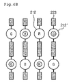
- the clusters shown in this set are arranged in a row of eight LEDs. There are five of these clusters arranged such that four are in each of the corners and one is in the center of the PCB 114 . Additionally, two smaller clusters are shown on either side of the PCB 114 . The smaller clusters are similar to the cluster embodiment shown in FIG. 7I .
- FIG. 11 is an alternate embodiment of a set of clusters.
- the clusters shown in FIG. 11 are similar to the cluster embodiment shown in FIG. 7E .
- the set of clusters shown in FIG. 11 has ten clusters arranged in a “XX” pattern.
- FIG. 12 is an alternate embodiment of a set of clusters.
- the clusters shown in FIG. 12 are similar to the cluster embodiment shown in FIG. 7E .
- the set shown in FIG. 12 includes an arrangement of clusters in adjacent diamond shapes.
- FIGS. 8-12 are merely exemplary embodiments of a set of clusters. Additional arrangements of clusters in a set is contemplated according to alternative embodiments. Alternate clusters may be used for the embodiments of a set of clusters than those clusters shown in FIGS. 7A-12 .
- FIG. 13 is an illustration of a combination of sets of clusters. Specifically, the embodiment of FIG. 13 is a combination of the set embodiment shown in FIG. 6 .
- FIG. 13 shows that sets of clusters can be combined or arranged together to create a backlight assembly producing improved brightness. In alternate embodiments of combinations of sets, the clusters and the sets may be arranged or combined differently than the exemplary embodiment shown in FIG. 13 .
- the LCD display may include any combination of sets as shown in FIG. 13 .
- the display may only include a single set of any number of clusters as described above.
- the display may include only a single cluster.
- the structures of the LEDs 212 and 212 ′ are not limited to the structures or sets of clusters shown in FIGS. 8-12 .
- the structures of the LEDs 212 and 212 ′ may be modified in various arrangements without departing from the scope of the present disclosure. In other words, the arrangement of the LEDs within the clusters, the arrangement of the clusters within a set, and the arrangement of the sets for a combination of sets may all be modified in alternate embodiments.
- the present embodiments may implement a backlight assembly and the LCD having the same, capable of obtaining high efficiency and high brightness using the small number of LEDs.
- the LCD may provide high efficiency and stabilized brightness, an intermediate light guide plate can be omitted, thereby reducing the cost of materials and the number of manufacturing processes and implement low power consumption.
Landscapes
- Physics & Mathematics (AREA)
- Nonlinear Science (AREA)
- Mathematical Physics (AREA)
- Chemical & Material Sciences (AREA)
- Crystallography & Structural Chemistry (AREA)
- General Physics & Mathematics (AREA)
- Optics & Photonics (AREA)
- Planar Illumination Modules (AREA)
- Led Device Packages (AREA)
- Liquid Crystal (AREA)
Abstract
Description
Claims (24)
Applications Claiming Priority (3)
| Application Number | Priority Date | Filing Date | Title |
|---|---|---|---|
| KR10-2005-0072076 | 2005-08-08 | ||
| KR72076/2005 | 2005-08-08 | ||
| KR1020050072076A KR101225326B1 (en) | 2005-08-08 | 2005-08-08 | Backlight assembly and liquid crystal display device having the same |
Publications (2)
| Publication Number | Publication Date |
|---|---|
| US20070030694A1 US20070030694A1 (en) | 2007-02-08 |
| US7651234B2 true US7651234B2 (en) | 2010-01-26 |
Family
ID=37717464
Family Applications (1)
| Application Number | Title | Priority Date | Filing Date |
|---|---|---|---|
| US11/412,801 Expired - Fee Related US7651234B2 (en) | 2005-08-08 | 2006-04-27 | Backlight assembly and liquid crystal display having the same |
Country Status (6)
| Country | Link |
|---|---|
| US (1) | US7651234B2 (en) |
| JP (1) | JP4335891B2 (en) |
| KR (1) | KR101225326B1 (en) |
| CN (1) | CN100520527C (en) |
| FR (1) | FR2889602B1 (en) |
| TW (1) | TWI354836B (en) |
Cited By (6)
| Publication number | Priority date | Publication date | Assignee | Title |
|---|---|---|---|---|
| US20080284946A1 (en) * | 2007-05-15 | 2008-11-20 | Makoto Abe | Lighting System and Liquid Crystal Display Using the Same |
| US20090211130A1 (en) * | 2005-05-19 | 2009-08-27 | Hoffman Joseph A | Thin internally illuminated sign |
| US20100133083A1 (en) * | 2006-02-20 | 2010-06-03 | Citizen Electronics Co., Ltd | Side-surface light-emitting unit and illuminated panel using the same |
| US20130182377A1 (en) * | 2012-01-18 | 2013-07-18 | Hannspree, Inc. | Electronic device having an adjustable angle support by engagement between resilient protrusions and recesses |
| US20150214196A1 (en) * | 2010-07-19 | 2015-07-30 | Epistar Corporation | Multi-dimensional light-emitting device |
| US10948769B1 (en) * | 2019-12-12 | 2021-03-16 | Asti Global Inc., Taiwan | Image display and backlight module thereof |
Families Citing this family (20)
| Publication number | Priority date | Publication date | Assignee | Title |
|---|---|---|---|---|
| JP4962884B2 (en) * | 2006-06-06 | 2012-06-27 | 三国電子有限会社 | Surface light source device, prism sheet and liquid crystal display device |
| WO2008138159A1 (en) * | 2007-05-14 | 2008-11-20 | M & M Public Design Ag | Lighting structure |
| TWI306142B (en) * | 2007-05-16 | 2009-02-11 | Ama Precision Inc | Led table lamp |
| TWI323329B (en) * | 2007-06-13 | 2010-04-11 | Ama Precision Inc | Led lighting system |
| JP2010020995A (en) * | 2008-07-10 | 2010-01-28 | Epson Imaging Devices Corp | Planar lighting device, electrooptical device, and electronic apparatus |
| JPWO2010146892A1 (en) * | 2009-06-15 | 2012-12-06 | シャープ株式会社 | LIGHTING DEVICE, DISPLAY DEVICE, AND TELEVISION RECEIVER |
| EP2426747A1 (en) * | 2009-06-15 | 2012-03-07 | Sharp Kabushiki Kaisha | Light emitting module, illuminating device, display device, and television receiver |
| WO2011025173A2 (en) * | 2009-08-27 | 2011-03-03 | Lg Electronics Inc. | Backlight unit and display device |
| KR101103944B1 (en) | 2010-02-03 | 2012-01-12 | 엘지이노텍 주식회사 | The light- |
| WO2011107928A1 (en) * | 2010-03-02 | 2011-09-09 | Koninklijke Philips Electronics N.V. | Led with transparent package |
| JP5506483B2 (en) * | 2010-03-19 | 2014-05-28 | 日立コンシューマエレクトロニクス株式会社 | Liquid crystal display device and lighting device |
| JP5264836B2 (en) * | 2010-07-12 | 2013-08-14 | 三菱電機株式会社 | Light emitting unit and light emitting device |
| JP6025309B2 (en) * | 2011-06-29 | 2016-11-16 | シャープ株式会社 | Light source device and liquid crystal display device |
| JP5731418B2 (en) * | 2012-01-23 | 2015-06-10 | シャープ株式会社 | Illumination device and liquid crystal display device including the same |
| TWI509845B (en) * | 2012-03-15 | 2015-11-21 | Lextar Electronics Corp | Light source module |
| JP2014143054A (en) * | 2013-01-23 | 2014-08-07 | Hitachi Consumer Electronics Co Ltd | Led lighting device |
| KR102320143B1 (en) * | 2015-02-13 | 2021-11-02 | 삼성디스플레이 주식회사 | Display device |
| CN104728682B (en) * | 2015-04-08 | 2018-01-05 | 武汉华星光电技术有限公司 | Backlight module and the liquid crystal display device for including it |
| WO2017094840A1 (en) * | 2015-12-02 | 2017-06-08 | シャープ株式会社 | Illumination device, display device, and television receiver |
| JP6932910B2 (en) * | 2016-10-27 | 2021-09-08 | 船井電機株式会社 | Display device |
Citations (8)
| Publication number | Priority date | Publication date | Assignee | Title |
|---|---|---|---|---|
| US20040213017A1 (en) * | 2003-04-22 | 2004-10-28 | Shen-Hong Chou | [light source of back light module] |
| JP2004303578A (en) | 2003-03-31 | 2004-10-28 | Toyoda Gosei Co Ltd | Surface light source device |
| US20050001537A1 (en) * | 2003-03-28 | 2005-01-06 | Lumileds Lighting U.S., Llc | Multi-colored LED array with improved brightness profile and color uniformity |
| US20060087866A1 (en) * | 2004-10-22 | 2006-04-27 | Ng Kee Y | LED backlight |
| US20060203466A1 (en) * | 2005-03-11 | 2006-09-14 | Samsung Electronics, Co., Ltd. | Light emitting panel and backlight system having the same and liquid crystal display device having the backlight system |
| US20070035966A1 (en) * | 2004-04-23 | 2007-02-15 | Naoto Ide | Surface light source device and display device |
| US7229194B2 (en) * | 2005-06-01 | 2007-06-12 | Au Optronics Corporation | Direct-type backlight unit structure |
| US7314296B2 (en) * | 2003-12-08 | 2008-01-01 | Honeywell International Inc. | Multi-platform aircraft forward position light utilizing LED-based light source |
Family Cites Families (3)
| Publication number | Priority date | Publication date | Assignee | Title |
|---|---|---|---|---|
| JP3927011B2 (en) | 2001-08-20 | 2007-06-06 | 株式会社 日立ディスプレイズ | Liquid crystal display device and its driving circuit |
| JP2003330424A (en) * | 2002-05-10 | 2003-11-19 | Hitachi Ltd | Liquid crystal display |
| JP4140710B2 (en) | 2003-03-04 | 2008-08-27 | 三菱電機株式会社 | Display device |
-
2005
- 2005-08-08 KR KR1020050072076A patent/KR101225326B1/en not_active Expired - Fee Related
-
2006
- 2006-04-27 US US11/412,801 patent/US7651234B2/en not_active Expired - Fee Related
- 2006-06-02 FR FR0604951A patent/FR2889602B1/en not_active Expired - Fee Related
- 2006-06-08 JP JP2006159466A patent/JP4335891B2/en not_active Expired - Fee Related
- 2006-06-28 TW TW095123428A patent/TWI354836B/en not_active IP Right Cessation
- 2006-06-30 CN CNB2006100865948A patent/CN100520527C/en not_active Expired - Fee Related
Patent Citations (8)
| Publication number | Priority date | Publication date | Assignee | Title |
|---|---|---|---|---|
| US20050001537A1 (en) * | 2003-03-28 | 2005-01-06 | Lumileds Lighting U.S., Llc | Multi-colored LED array with improved brightness profile and color uniformity |
| JP2004303578A (en) | 2003-03-31 | 2004-10-28 | Toyoda Gosei Co Ltd | Surface light source device |
| US20040213017A1 (en) * | 2003-04-22 | 2004-10-28 | Shen-Hong Chou | [light source of back light module] |
| US7314296B2 (en) * | 2003-12-08 | 2008-01-01 | Honeywell International Inc. | Multi-platform aircraft forward position light utilizing LED-based light source |
| US20070035966A1 (en) * | 2004-04-23 | 2007-02-15 | Naoto Ide | Surface light source device and display device |
| US20060087866A1 (en) * | 2004-10-22 | 2006-04-27 | Ng Kee Y | LED backlight |
| US20060203466A1 (en) * | 2005-03-11 | 2006-09-14 | Samsung Electronics, Co., Ltd. | Light emitting panel and backlight system having the same and liquid crystal display device having the backlight system |
| US7229194B2 (en) * | 2005-06-01 | 2007-06-12 | Au Optronics Corporation | Direct-type backlight unit structure |
Non-Patent Citations (1)
| Title |
|---|
| First Office Action for corresponding Chinese Patent Application Serial No. 200610086594.8, dated Sep. 28, 2007. |
Cited By (10)
| Publication number | Priority date | Publication date | Assignee | Title |
|---|---|---|---|---|
| US20090211130A1 (en) * | 2005-05-19 | 2009-08-27 | Hoffman Joseph A | Thin internally illuminated sign |
| US8789299B2 (en) * | 2005-05-19 | 2014-07-29 | 3M Innovative Properties Company | Thin internally illuminated sign |
| US20100133083A1 (en) * | 2006-02-20 | 2010-06-03 | Citizen Electronics Co., Ltd | Side-surface light-emitting unit and illuminated panel using the same |
| US7884296B2 (en) * | 2006-02-20 | 2011-02-08 | Citizen Electronics Co., Ltd. | Side-surface light-emitting unit and illuminated panel using the same |
| US20080284946A1 (en) * | 2007-05-15 | 2008-11-20 | Makoto Abe | Lighting System and Liquid Crystal Display Using the Same |
| US8284350B2 (en) * | 2007-05-15 | 2012-10-09 | Hitachi, Ltd. | Lighting system and liquid crystal display using the same |
| US20150214196A1 (en) * | 2010-07-19 | 2015-07-30 | Epistar Corporation | Multi-dimensional light-emitting device |
| US9385108B2 (en) * | 2010-07-19 | 2016-07-05 | Epistar Corporation | Light-emitting device having optoelectronic elements on different elevations |
| US20130182377A1 (en) * | 2012-01-18 | 2013-07-18 | Hannspree, Inc. | Electronic device having an adjustable angle support by engagement between resilient protrusions and recesses |
| US10948769B1 (en) * | 2019-12-12 | 2021-03-16 | Asti Global Inc., Taiwan | Image display and backlight module thereof |
Also Published As
| Publication number | Publication date |
|---|---|
| JP4335891B2 (en) | 2009-09-30 |
| TW200707024A (en) | 2007-02-16 |
| CN100520527C (en) | 2009-07-29 |
| FR2889602A1 (en) | 2007-02-09 |
| KR101225326B1 (en) | 2013-01-23 |
| FR2889602B1 (en) | 2012-01-06 |
| JP2007048740A (en) | 2007-02-22 |
| KR20070017603A (en) | 2007-02-13 |
| US20070030694A1 (en) | 2007-02-08 |
| CN1912712A (en) | 2007-02-14 |
| TWI354836B (en) | 2011-12-21 |
Similar Documents
| Publication | Publication Date | Title |
|---|---|---|
| US7651234B2 (en) | Backlight assembly and liquid crystal display having the same | |
| KR101237788B1 (en) | LED light emitting unit and LED backlight assembly and liquid crystal display module | |
| CN100541289C (en) | Display device and backlight device | |
| US7780312B2 (en) | Backlight assembly for liquid crystal display device and liquid crystal display device using the same | |
| JP5066572B2 (en) | Backlight unit and liquid crystal display device including the same | |
| US7530711B2 (en) | Backlight assembly and liquid crystal display module using the same | |
| EP1737051B1 (en) | Backlight assembly including light emitting diode and display device including the same | |
| EP2120088B1 (en) | Backlight Unit Including Light Emitting Diodes and Liquid Crystal Display Device Including the Same | |
| EP2068378B1 (en) | LED backlight for a liquid crystal display device | |
| US9091882B2 (en) | Light emitting module, surface light source, liquid crystal display, and illuminating device | |
| US20120063122A1 (en) | Illumination device, display device, and television receiver | |
| WO2011004637A1 (en) | Illumination device, display device, and television receiver | |
| JP5244181B2 (en) | Lighting device, display device, and television receiver | |
| CN102803821A (en) | Lighting device, display device and television receiving device | |
| US20110211365A1 (en) | Light guide plate, and backlight unit | |
| KR20070006453A (en) | Light generating device and display device having same | |
| CN1837922A (en) | Light emitting assembly, backlight unit and display having the same | |
| KR20120065752A (en) | Liquid crystal display device | |
| WO2013024715A1 (en) | Illumination device, display device, television receiving device | |
| KR20080064490A (en) | Optical lens and backlight unit | |
| KR20140064183A (en) | Backlight unit and liquid crystal display module including the same | |
| KR20060095144A (en) | LED backlight assembly and liquid crystal display module using the same | |
| KR20060121442A (en) | Backlight Unit for Liquid Crystal Display | |
| KR20060105397A (en) | Light generating device and display device having same | |
| KR20070024861A (en) | Back light assembly and liquid crystal display device having same |
Legal Events
| Date | Code | Title | Description |
|---|---|---|---|
| AS | Assignment |
Owner name: LG. PHILIPS LCD CO., LTD., KOREA, REPUBLIC OF Free format text: ASSIGNMENT OF ASSIGNORS INTEREST;ASSIGNOR:LIM, DAE SAN;REEL/FRAME:017834/0771 Effective date: 20060427 |
|
| AS | Assignment |
Owner name: LG DISPLAY CO., LTD., KOREA, REPUBLIC OF Free format text: CHANGE OF NAME;ASSIGNOR:LG PHILIPS LCD CO., LTD.;REEL/FRAME:020986/0231 Effective date: 20080229 Owner name: LG DISPLAY CO., LTD.,KOREA, REPUBLIC OF Free format text: CHANGE OF NAME;ASSIGNOR:LG PHILIPS LCD CO., LTD.;REEL/FRAME:020986/0231 Effective date: 20080229 |
|
| FEPP | Fee payment procedure |
Free format text: PAYOR NUMBER ASSIGNED (ORIGINAL EVENT CODE: ASPN); ENTITY STATUS OF PATENT OWNER: LARGE ENTITY |
|
| STCF | Information on status: patent grant |
Free format text: PATENTED CASE |
|
| CC | Certificate of correction | ||
| FPAY | Fee payment |
Year of fee payment: 4 |
|
| FPAY | Fee payment |
Year of fee payment: 8 |
|
| FEPP | Fee payment procedure |
Free format text: MAINTENANCE FEE REMINDER MAILED (ORIGINAL EVENT CODE: REM.); ENTITY STATUS OF PATENT OWNER: LARGE ENTITY |
|
| LAPS | Lapse for failure to pay maintenance fees |
Free format text: PATENT EXPIRED FOR FAILURE TO PAY MAINTENANCE FEES (ORIGINAL EVENT CODE: EXP.); ENTITY STATUS OF PATENT OWNER: LARGE ENTITY |
|
| STCH | Information on status: patent discontinuation |
Free format text: PATENT EXPIRED DUE TO NONPAYMENT OF MAINTENANCE FEES UNDER 37 CFR 1.362 |
|
| FP | Lapsed due to failure to pay maintenance fee |
Effective date: 20220126 |